-
Where to source FT232RL?
12/01/2016 at 20:22 • 0 commentsI just did a quick Google search for FT232RL ... the only sources are > 3€.
So how it is possible to sell a
Ftdi Ft232rl Usb To Ttl Serial Converter Adapter Module 5v 3.3v Forat 1,59€ with free shipping?
For me the BOM would be something like 7€ + production + shipping + gain.
-
Update
11/30/2016 at 23:01 • 0 commentsUntil now it was not my Main Idea for this Board but in fact Datalogging is also a nice choice ;-)
I created a simple programm to read data from A0 and send it cyclically by Serial.
The intent of the Parameters is to calibrate the readout using some voltage reference values.
Simply note them in Excel and then calculate the correction equation.
The "GUI" is a weng German this time ;-)
Please find some code below :-)
/*
  Analog input, analog output, serial output

 Reads an analog input pin, maps the result to a virtual float Value
 and uses the result to calculate a Voltage Value and prints the results to the serial monitor.

 The circuit:
 * Connect some voltage potential to A0
 * Connect Ground to a common ground
 * Connect status LEDs on D3 (RED), 5(Blue), 6 (Green)
 * Optional: Connect RX/TX via BlueTooth

 created 29 Dec. 2008
 modified 9 Apr 2012 by Tom Igoe
 Extended 30.11.2016 by Stefan-Xp

 This example code is in the public domain.
  */

// These constants won't change.  They're used to give names
// to the pins used:
const int analogInPin = A0;  // Analog input pin that the potentiometer is attached to
const int analogOutPin = 9; // Analog output pin that the LED is attached to

int sensorValue = 0;        // value read from the pot
int outputValue = 0;        // value output to the PWM (analog out)

// Variable parameters
int factor = 1;
int offset = 0;
int delayS = 2;

// Ids for variable parameters
#define FACTOR 1
#define OFFSET 2
#define DELAY 3

int delayCount = 0; // Count for the Delay (Steps of 100ms)
byte inByte = 0;    // Input byte by Serial Port

void setup() {
  // initialize serial communications at 9600 bps:
  Serial.begin(9600);

  // Define some Outputs
  pinMode(3, OUTPUT);
  pinMode(5, OUTPUT);
  pinMode(6, OUTPUT);

  digitalWrite(5, HIGH);
}

// This sub writes the Raw and the calculated Value on the Serial
void printVoltage()
{
  int VoltageValue = 0;

  digitalWrite(5, LOW);
  digitalWrite(6, HIGH);

  sensorValue = analogRead(analogInPin);
  // map it to the range of the analog out:
  outputValue = map(sensorValue, 0, 1023, 0, 5000);
  VoltageValue = (outputValue*factor + offset);
  // change the analog out value:
  //analogWrite(analogOutPin, outputValue);

  // print the results to the serial monitor:
  Serial.print("RAW = " );
  Serial.print(outputValue);
  Serial.print("\t Voltage = ");
  Serial.print(VoltageValue/1000,DEC);
  Serial.print(",");
  if(abs(int(VoltageValue)%1000) < 100)
    Serial.print("0");
  if(abs(int(VoltageValue)%1000) < 10)
    Serial.print("0");
  Serial.print(abs(int(VoltageValue)%1000),DEC);
  Serial.println("V");


  delay(10);
  digitalWrite(5, HIGH);
  digitalWrite(6, LOW);
  return;
}

// This sub checks if there are Numbers entered by the Console.
void checkForNewNumberInput ()
{
   while(1)
   {
       if(Serial.available() > 0)
       {
         inByte = Serial.read();

         if(inByte >= '0' && inByte <= '9')
         {
           break;
         }
         else
         {
           Serial.print("Err : ");
           Serial.print(inByte);
           Serial.print(" ");
           Serial.println((char)inByte);
         }
       }

   }
}

// This sub sets a parameter with 4 bytes of numbers from Serial
void setParameter(byte Parameter)
{
  float Value = 0;

  digitalWrite(3, HIGH);
  digitalWrite(6, LOW);

  Serial.print(" eingeben: ");

  checkForNewNumberInput();
  Value = (inByte-'0')*1000;
  checkForNewNumberInput();
  Value = (Value + (inByte-'0')*100);
  checkForNewNumberInput();
  Value = (Value + (inByte-'0')*10);
  checkForNewNumberInput();
  Value = (Value + (inByte-'0'));

  switch(Parameter)
  {
     case FACTOR: Serial.print("Factor = "); factor = Value/1000; break;
     case OFFSET: Serial.print("Offset = "); offset = Value; break;
     case DELAY:  Serial.print("Delay = "); delayS = Value; break;
  }

  Serial.println(Value);
  digitalWrite(3, LOW);
  digitalWrite(6, HIGH);
}

// The usual thing..
void loop() {
  // read the analog in value:
  if(delayCount >= delayS*10)
  {
    printVoltage();
    delayCount = 0;
  }
  delayCount++;

  // if there is new Data on the Serial...
  if (Serial.available() > 0)
  {
    // get incoming byte:
    inByte = Serial.read();
    Serial.print("Bitte ");
    switch(inByte)
    {
      case 'f': Serial.print("Factor [1.000]");
                setParameter(FACTOR);
                break;

      case 'o': Serial.print("Offset [10.00]");
                setParameter(OFFSET);
                break;

      case 't': Serial.print("Zeitabstand [s]:");
                setParameter(DELAY);
                break;

      case 'i':
      case '?': Serial.println();
                Serial.println("*** AnalogDataLogger V1.0");
                Serial.println("*** 2016-11-30 Stefan-Xp");
                Serial.println("* f = Factor in Tausendstel 1x = 1000");
                Serial.println("* o = Offset in Hundertstel +1 = 0100");
                Serial.println("* t = Time in Sekunden 10s     = 0010");
                Serial.println("* i = Info");
                Serial.println("** Aktuelle Parameter:");
                Serial.print("* f = Factor = ");
                Serial.println(factor);
                Serial.print("* o = Offset = ");
                Serial.println(offset);
                Serial.print("* t = Time   = ");
                Serial.println(delayS);
                //Let it stay at least 5s
                delay(5000);
                break;
                i
      default:  Serial.println(" gueltigen Key eingeben!");
    }
  }

  // wait 100 milliseconds before the next loop
  // for the analog-to-digital converter to settle
  // after the last reading:
  delay(100);
}
Still nothing for the 1k Challenge ;)
-
Time for a Update
11/19/2016 at 17:13 • 1 comment -
Microchip RN4020
07/29/2015 at 21:12 • 0 commentsI recently found the RN4020 - Looks like an awesome module:
http://ww1.microchip.com/downloads/en/DeviceDoc/50002279A.pdf
Perhapps it would work more like i wanted and also is better sourceable ;-)
-
Android Studio :)
03/10/2015 at 20:13 • 3 commentsSo obviousely the next step would be to create an app there for.
But I'm not motivated at the moment :-/ too bad...
-
Long time no see...
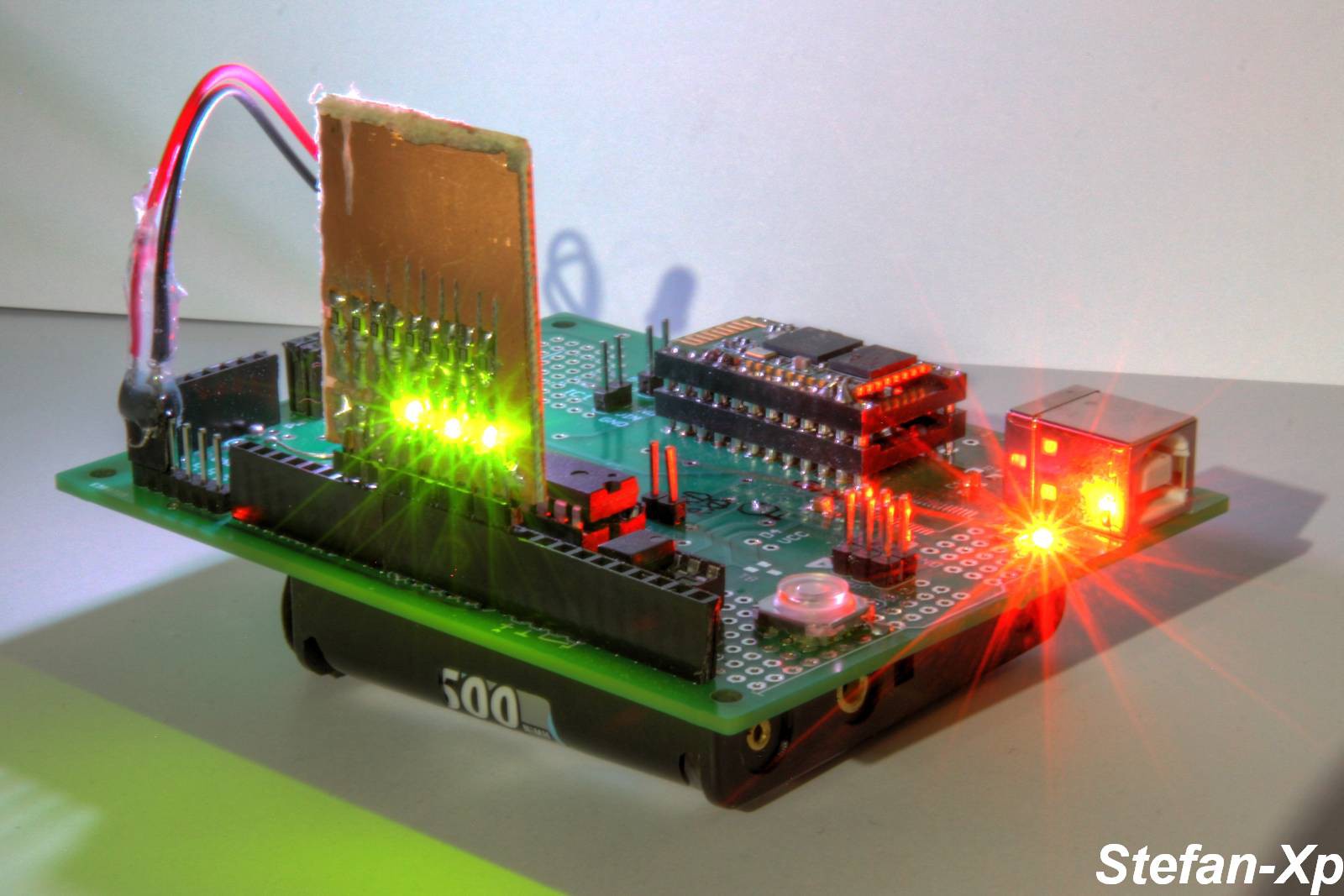
02/19/2015 at 20:34 • 3 commentsWell there it is ... the Hardware ;-)
Designed in December 2000 and 13...and delivered a bit longer than a year ago.
On the plus side:
+ at least the serial connection via BlueTooth works.
+ It has a LM7805 Footprint
+ It has a mostly working EGBT-045MS
+ I can control LEDs via my Smartphone and a nice App "Bluetooth spp pro"
+ Arduino compatible
+ Convenient half euro card size
+ Footprint for FT232RL (also working ;))
On the minus side:
- can't get the BT Module to work as Master/Server
- no foodprints for SMD-keys
- No good capability of stacking other boards :-(
-
The general idea...
01/28/2015 at 20:26 • 1 commentIn general my Idea was to use a BT Master Module (Tried with EGBT-045MS (as i assumed)..)
I thought it would report identificable BT Devices. Somehow it nearly doesn't respond anymore if i set it to Mastermode and Inquire.
After Getting the BT ID, i would check if the RSSI is over a certain threshold and enable a Button to unlock the door... But first i have to find an other BT Master module or get it running ...
Furious Tooth Fairy - Door Unlock
This is a small pcb with ATMega328p and BlueTooth HC-05
 Stefan-Xp
