So, i found the Q10 Keyboard for my project and JoeN from the EEVBlog Forum also already did the work to reverse engineer the Keyboard matrix.
But as i know that this keyboard can also be backlit i wanted to to get the backlight running.
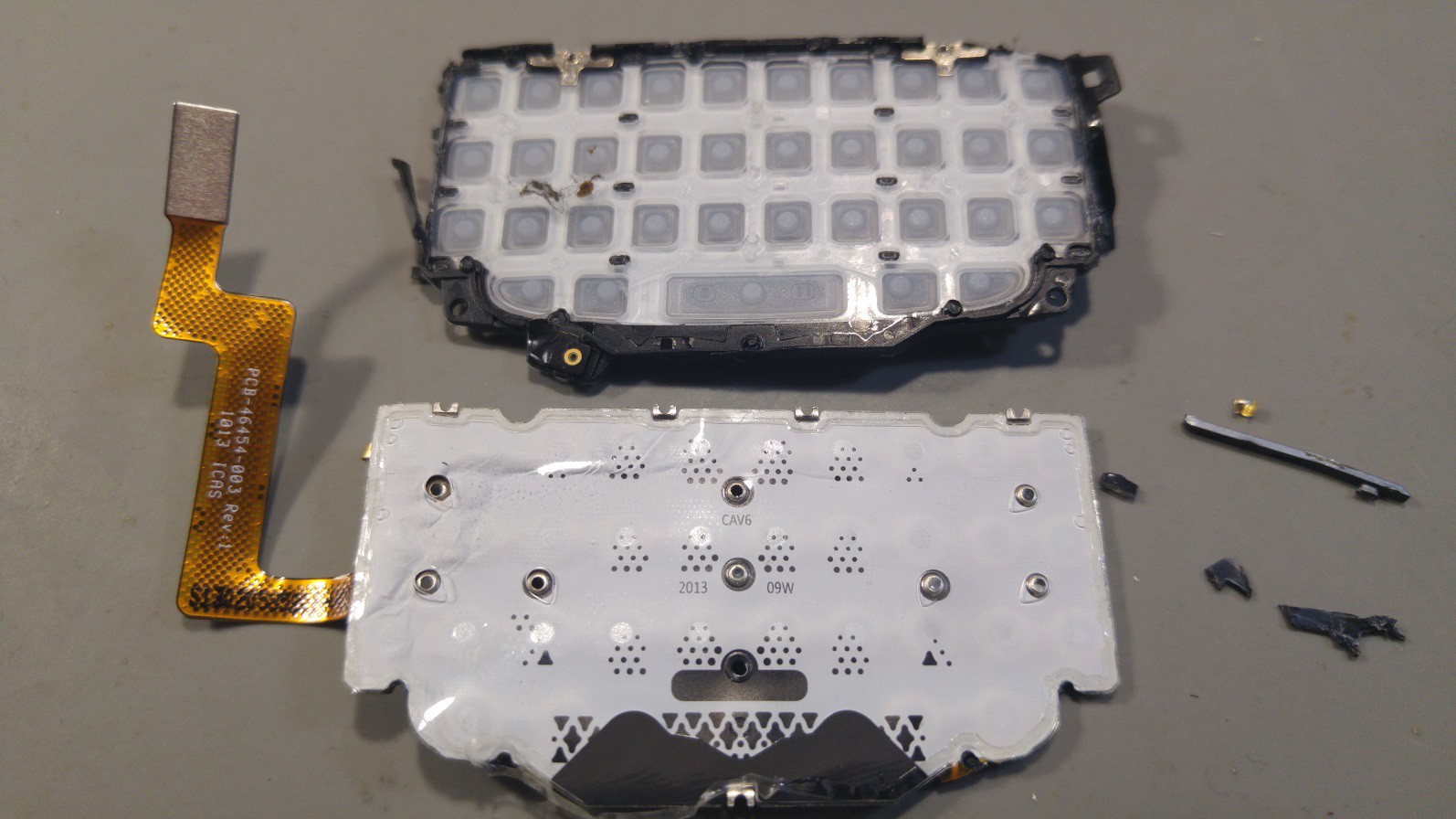
At first i tried just the good old try all the pins with all the other pins in Diode testing mode - and i did not really get much out of this. So as Dave Jones always says: “Don't turn it on, take it apart”, i then took it apart.


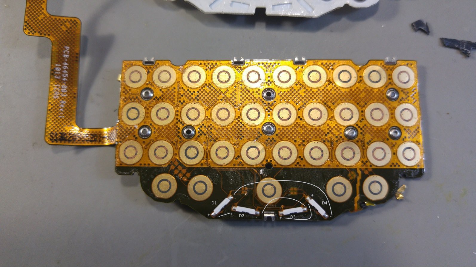
I found a lot of nice metallic tactile domes for the keys, a few Resistors AND 4 LEDs.
Now that i had access to the LEDs i was testing them directly with the diode test mode of my DMM and there they are White LEDs with 2.5v diode drop.
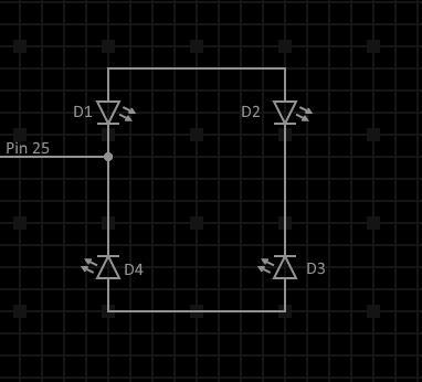
Then i beeped out the connections of the diodes and got a really strange back to back front to front arrangement.

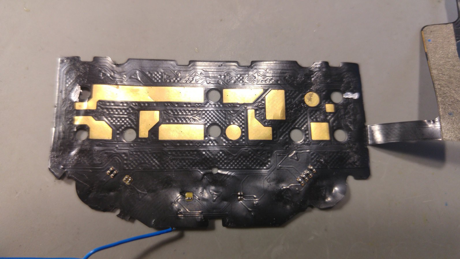
But while removing the flex pcb from the metal back i ripped of one of the resistors, and as i only have one keyboard left, i’ll wait for the next Aliexpress shipment of 6 of them to take another one apart and find the missing connections.

But i found the grounds and one LED connection for that connector. Hopefully i’ll find them all when i can take another one, more carefully, apart. If anyone has any tips on what this strange LED arrangement is please tell.
JoeN Connector Pinout + my findings
GND   28     1    GND
ROW7  27     2
      26     3
D1-   25     4
      24     5
      23     6    ROW1
ROW6  22     7    COL1
ROW5  21     8    ROW2
ROW4  20     9    COL2
COL5  19    10    COL3
ROW3  18    11    GND
COL4  17    12    GND
      16    13    GND
      15    14
 WooDWorkeR
Discussions
Become a Hackaday.io Member
Create an account to leave a comment. Already have an account? Log In.
I'm looking into this again and somehow I don't get the backlight LEDs connection. Except of pin 25, where else are the diodes connected? Where is GND connected?
I'd expect only COL/ROW pins of button matrix to be available.
Are you sure? yes | no
my connector was not soldered correctly - i found all 4 connections of the diodes (Pin 23-26)
Did tests on the connector soldered to the flex PCB
Will retest the GND connections i already found
Are you sure? yes | no
Oh, now it makes sense about the diodes. So, each one of four junctions between diodes goes to one of four pins 23,24,25 and 26.
What about the passives? Those are probably resistors, I can see probably smaller ones 4 of them routed somewhere along the LED nets, but then there are also somehow bigger ones. Are those pull-up or pull-downs for rows or columns? As if I didn't bother you enough with the questions - please, try to measure resistance between GND pins and rows/columns, I expect the resistors to have resistance in order of tens of kiloohms. Maybe there is another (yet unmarked) pin that connects all the common resistors nets.
Are you sure? yes | no
all the passives seem to be resistors at 1-2 Ohms, no kilo - the group 4 resistors left and right seem to be connected to the bottom row of the keyboard which contain left and right shift, mic key, space and symbol key
Are you sure? yes | no
That's useful information, thank you much for measurement. Seems I was wrong about the pull-ups.
Are you sure? yes | no
looks like every "node" is connected to a resistor. Probaly to save ground wires for the leds, they still need to route four pins/ wires but use one signal as ground and one as vcc pin.
Are you sure? yes | no