Nikos
Nikos-
Back to LED flashing!
01/22/2019 at 12:30 • 2 commentsLook ma, no stencil!
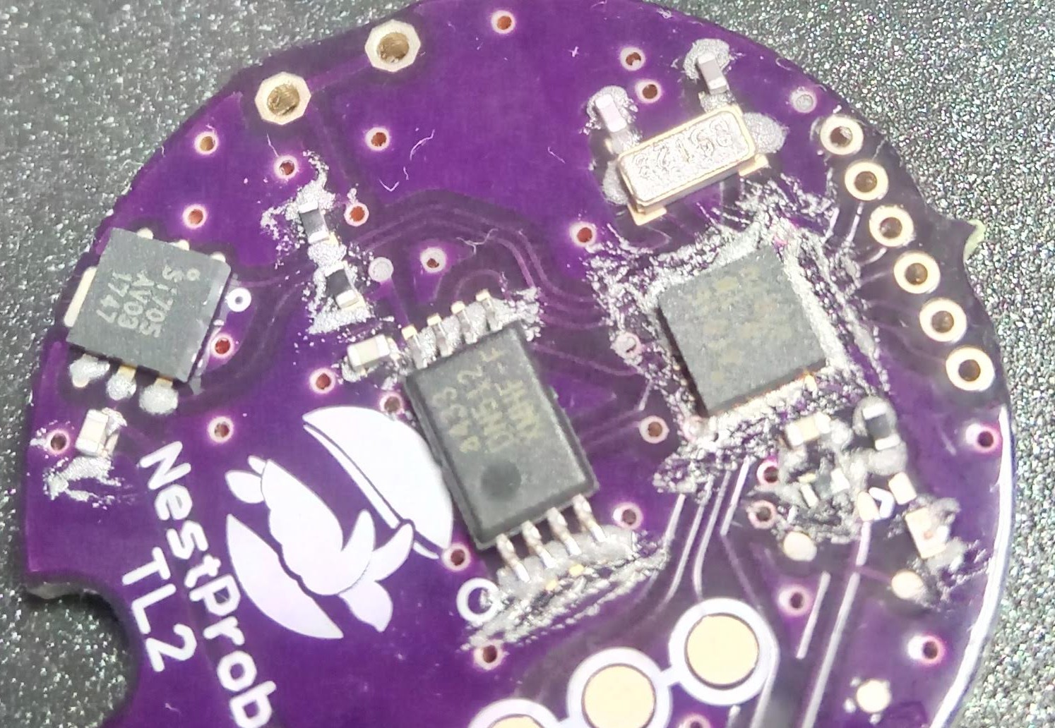
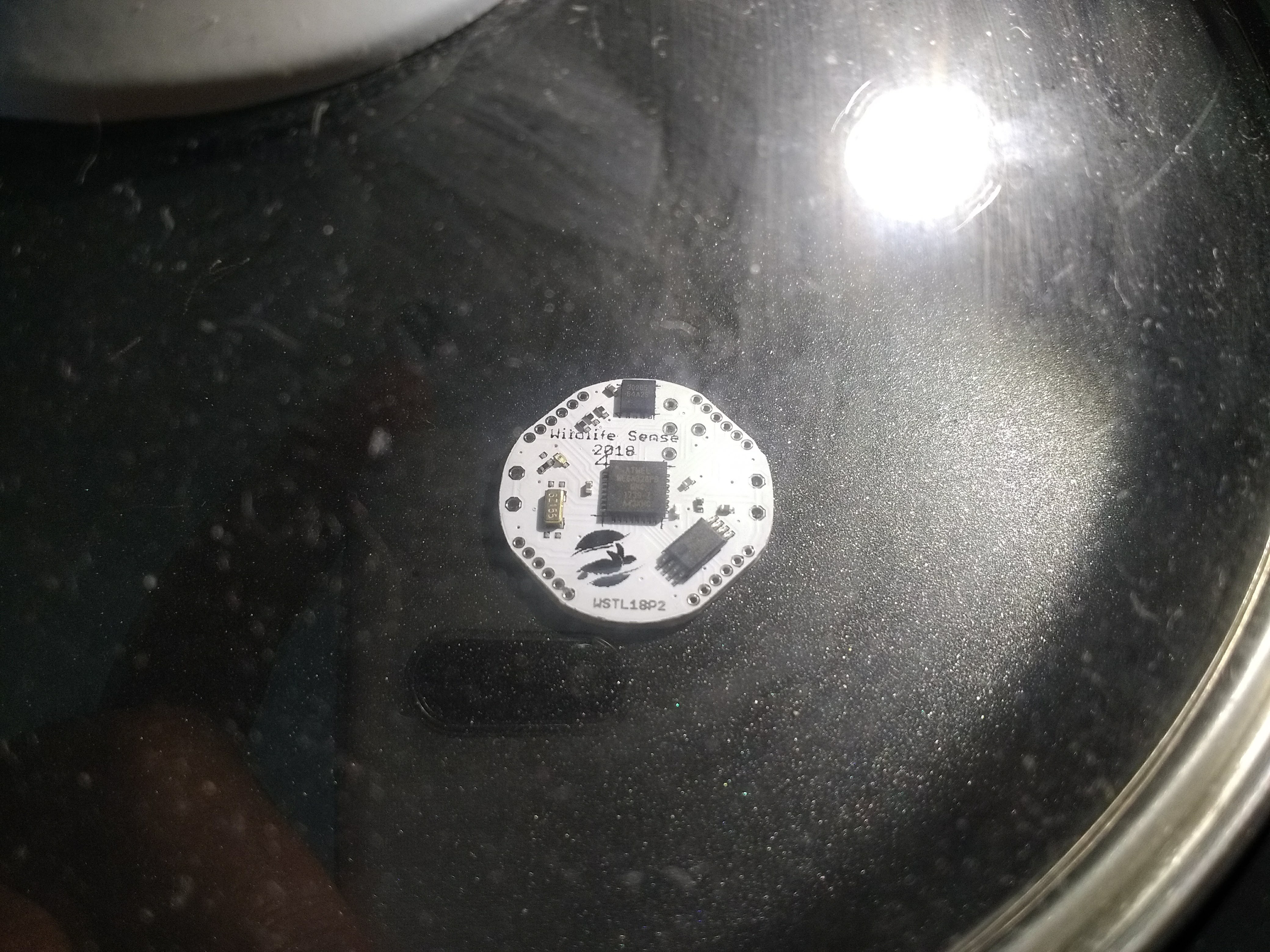
I went cheap and didn't order a stencil for the TL2 prototype. After hand-placing the solder paste, chips, and passive components on the board, I was pretty sure it wouldn't work. Take a look at the badly spread paste around the ATtiny816 to the right:
![]()
It had a few bridges after it came out of the frying pan/skillet. I did the best I could with some solder wick and had no visible bridges. Everything else looked fine courtesy of using 0402 passives instead of TL1's 0201 which were a nightmare.
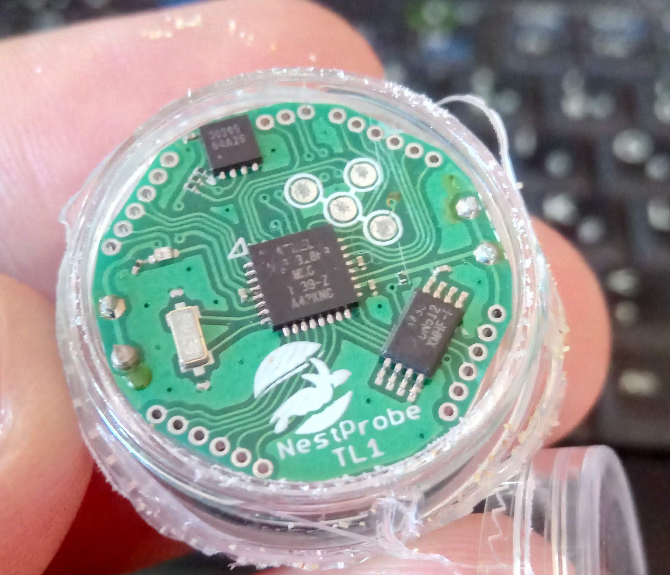
My first UPDI
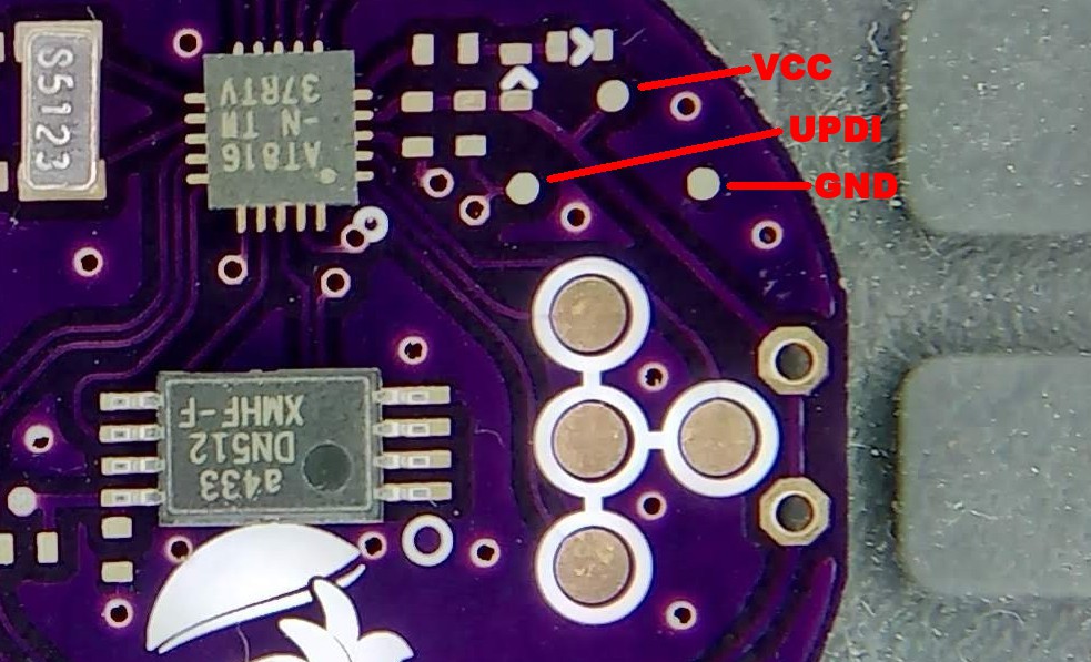
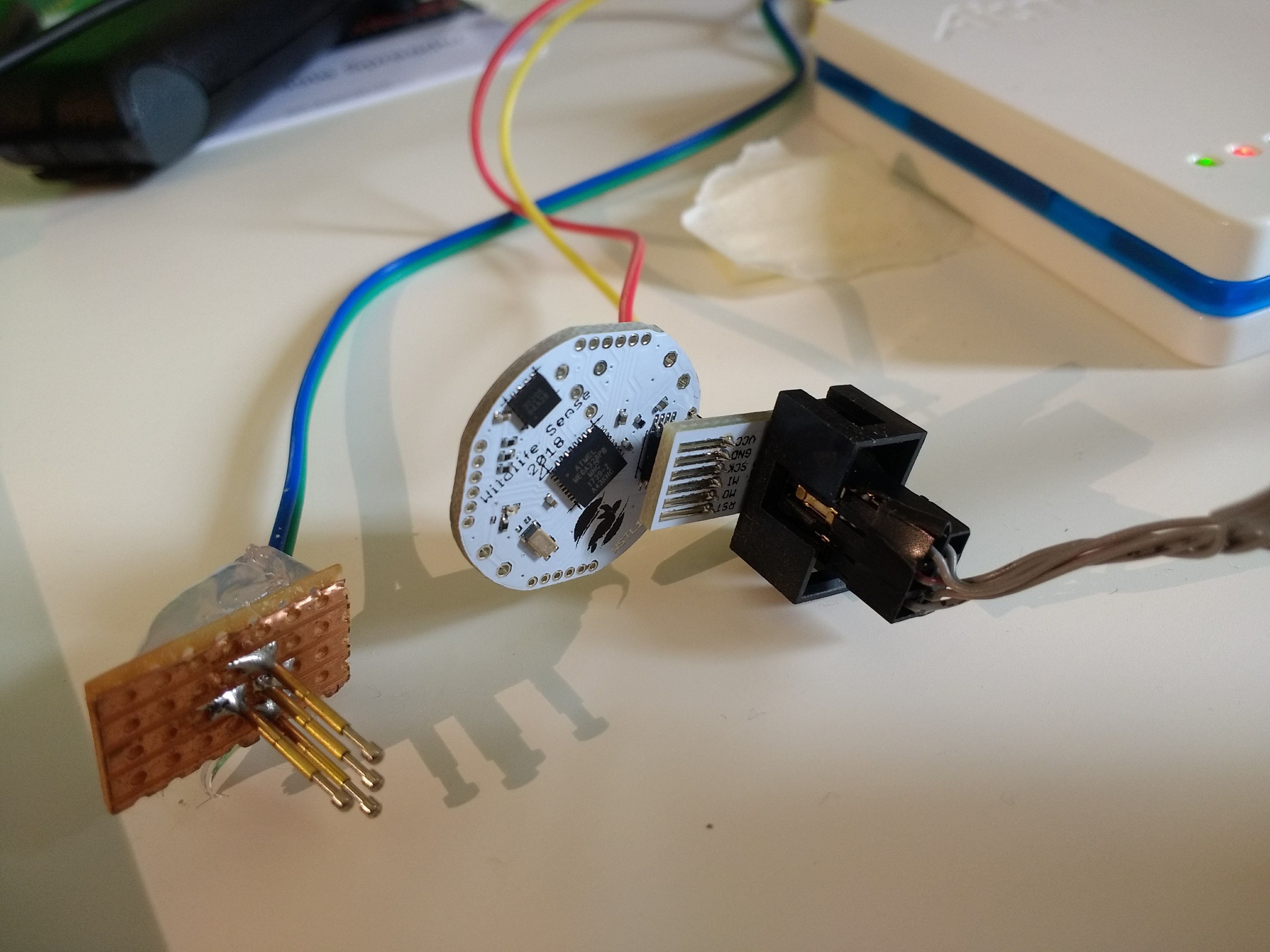
The problem here was that I have to use UPDI to program the ATtiny816. It's a new thing for me and if it didn't work I wouldn't be sure if it's the soldering or a setup problem. The UPDI only needs three connections: GND, VCC, and ... UPDI. I had designed those in with a set of surface pads which are tiny so they won't be confused with the data-download connector.
![]()
To use UPDI you have to have the Atmel-ICE programmer, which I did. There are some projects out there to bring UPDI to cheaper programmers but I haven't really looked into that.
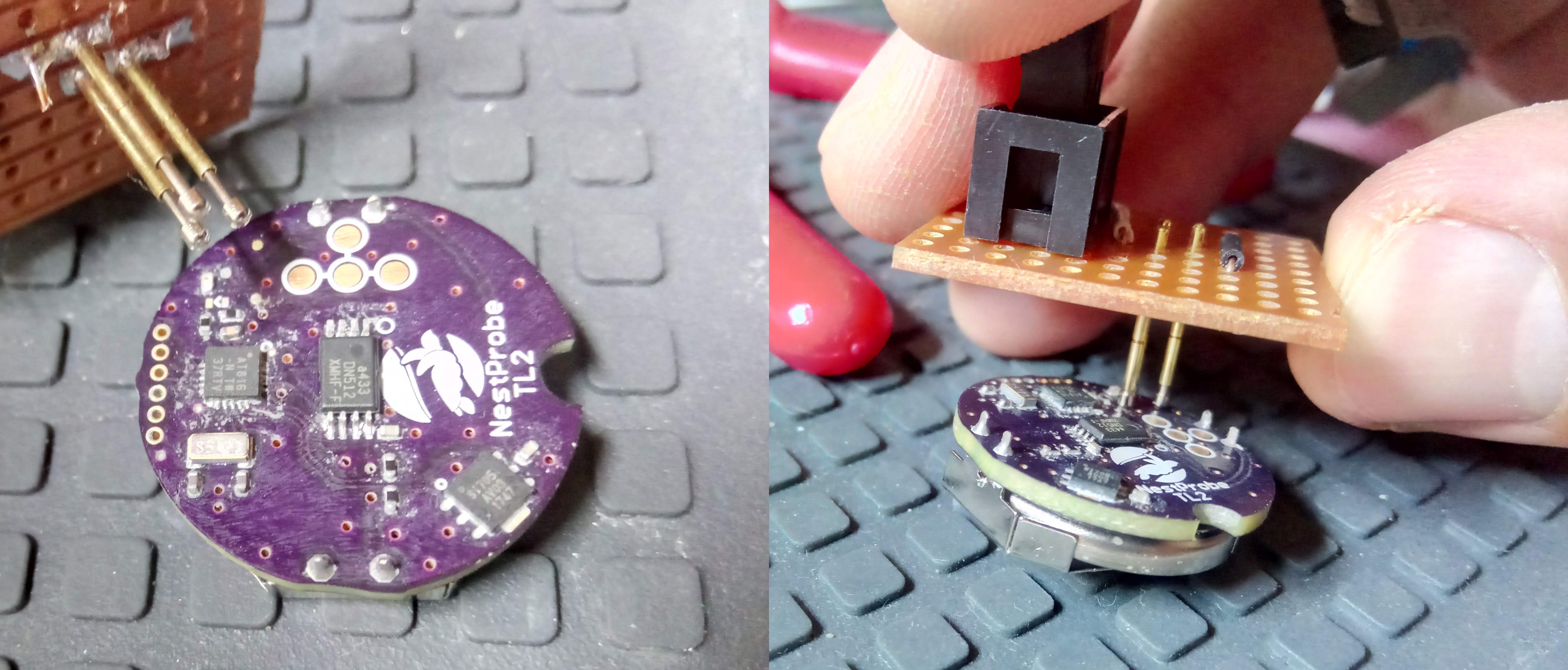
The surface pads on the TL2 are 0.1" apart in a 90° configuration so there's no orientation confusion. I made an adaptor to connect the 6-pin ISP connector to this board. The ICE uses the MISO wire for the UPDI line.
![]()
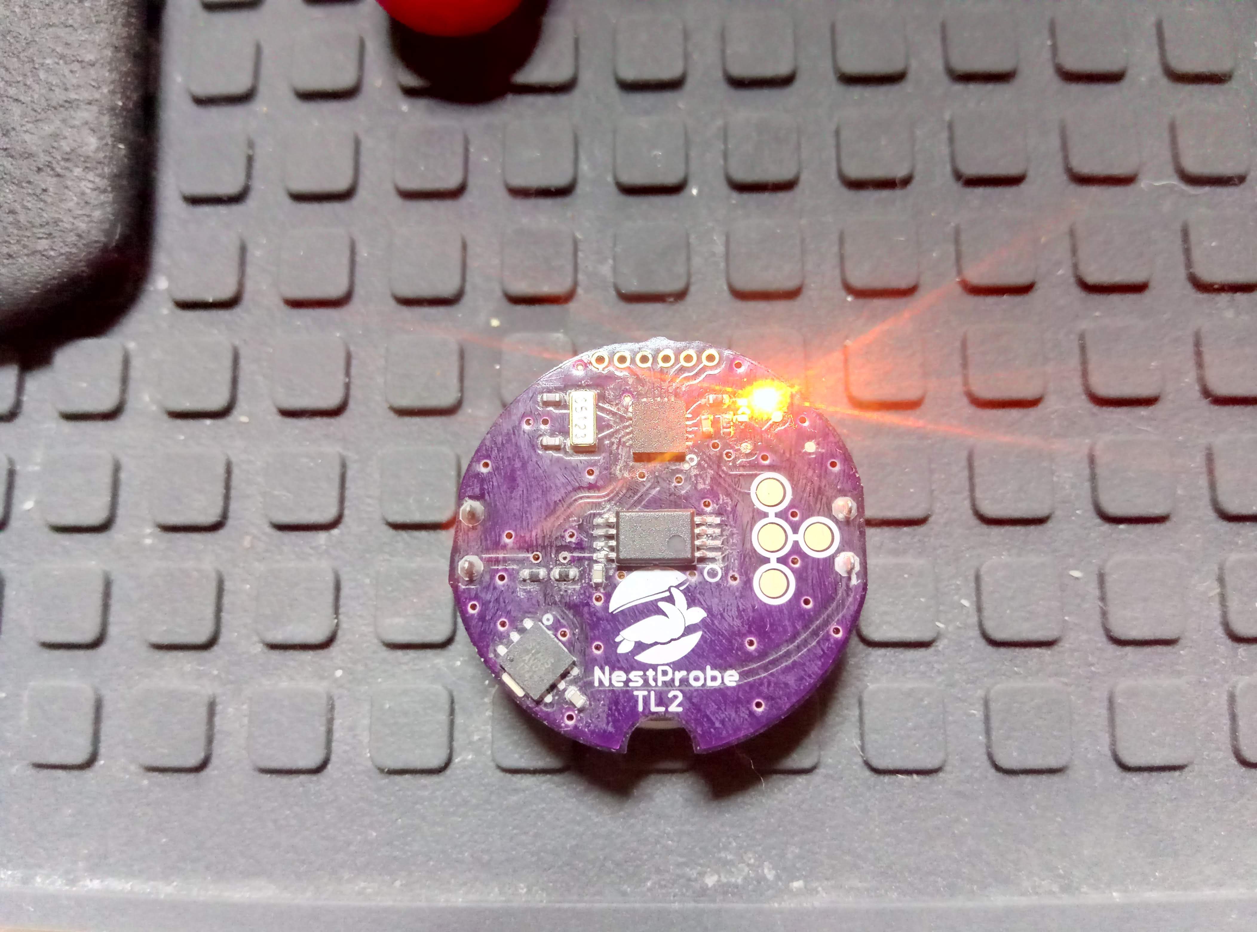
And it just worked! (phew)
I went to Atmel Start, set up a basic project with the ATtiny816, opened it on Atmel Studio and just added a couple of lines to initialize and toggle the LED on PA4. I had already been able to read the device's ID but it was nice to upload the firmware and see it work:
![]()
![]()
What's next?
This is an entirely new chip for me. Even though it's still AVR, programming is a little different from the familiar ATmegas. I'm also trying to learn embedded C++ so I'll be experimenting with that. My first goals are to connect to the also new (for me) temperature sensor (Si7051) and see how low I can get the system's power consumption to.
In terms of hardware, I want to add a small low-power accelerometer near the temperature sensor. This will allow us to see exactly when the hatchlings start moving in the nests. I'd also like to connect some more pins to break-out headers, which will allow the option to connect SPI and I2C to add-on boards for additional sensors and a LoRa transmitter.
-
Boards for TL2 are finally here!
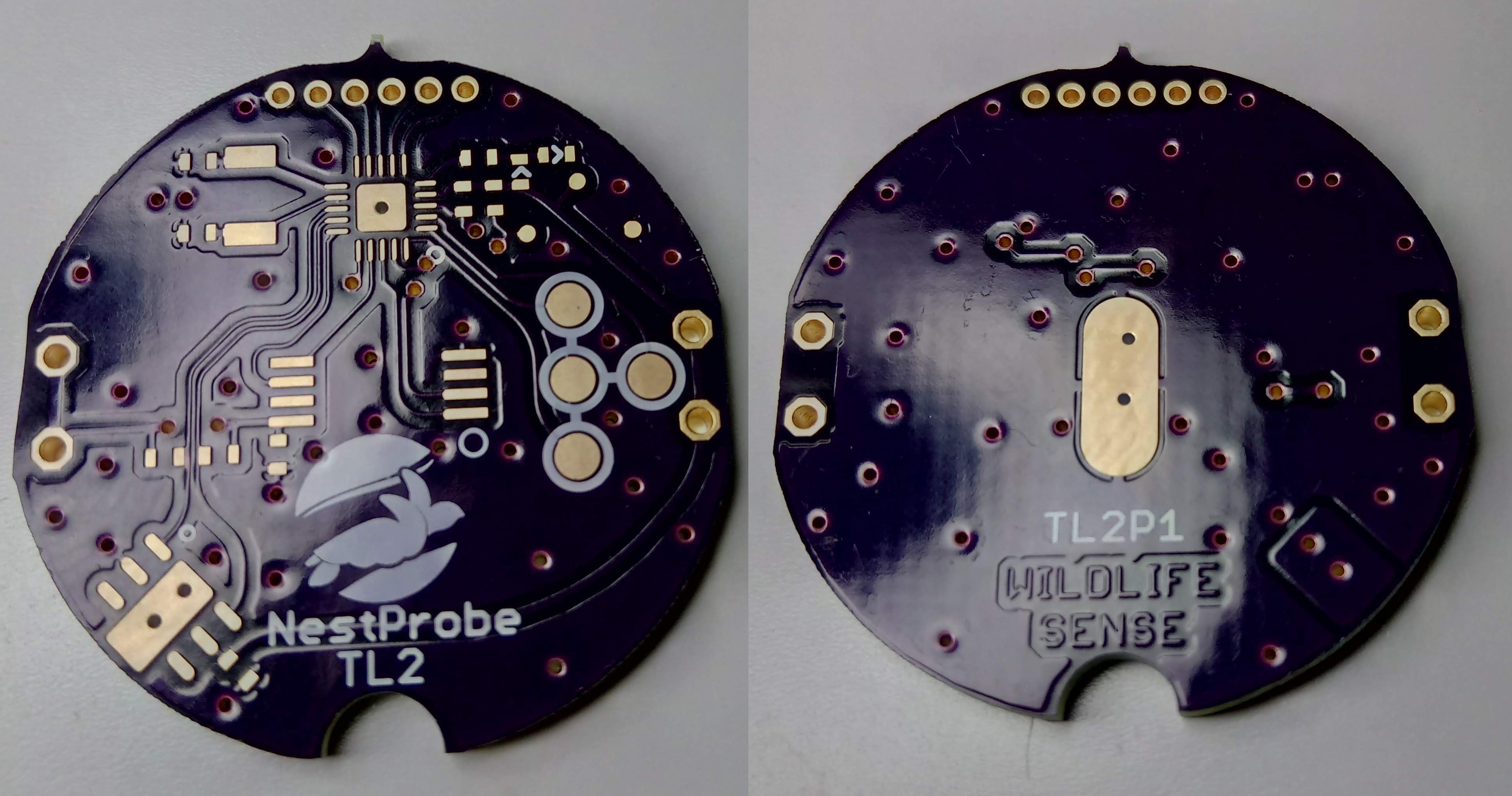
01/18/2019 at 14:01 • 0 commentsVery happy to have just received the PCBs for the next iteration of this temperature logger, the NestProbe TL2.
![]()
In an effort to reduce cost and complexity, I spent much of past autumn designing a new model of the temperature logger. Thanks to Jan who pointed out details about sensor accuracy, I also changed the temperature sensor to Silicon Labs' Si7051, which is more expensive but more accurate and NIST-traceable.
Main changes for this iteration are:
- Changed MCU to ATtiny816. The 328PB was great but a bit too much for such a simple application. The ATtiny is also almost half the cost, at just over 50 cents per unit, and it also has half the current consumption when in ultra-low-power.
- Changed temperature sensor to the Si7051. It is slightly more expensive than the MAX30205 but it's meant to be more accurate and has a NIST-traceable certificate. Let's see!
- Changed all passive components from 0201 to 0402. I had used 0201s for the TL1 because I was trying to break all MCU pins out to optional headers. With traces for 28 pins, I needed the space. That proved to be too difficult to solder with even the slightest problems in solder paste quality or concentration, and once I had problems in the first go it was too difficult to fix. The 0402s should make home-manufacturing much less painful.
- Fewer breakouts. I've traced five pins to a set of headers but I'm hoping in later prototypes to still break-out the rest of them. Especially I2C and SPI to allow additional sensors and connection to a LoRa module.
I'm looking forward to put this on the frying pan and start coding!
-
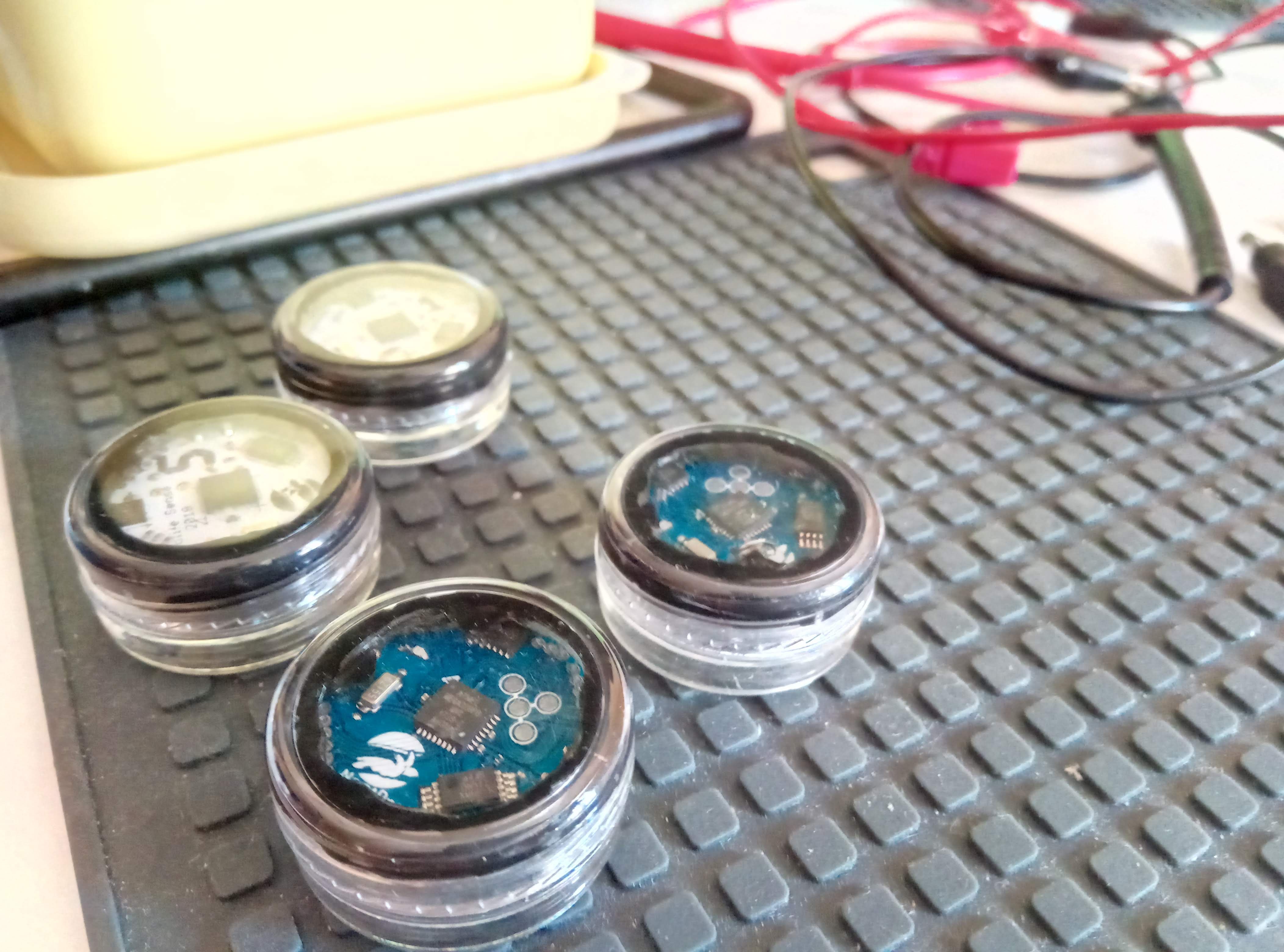
Review of case and sealing
09/14/2018 at 23:08 • 0 comments![]()
During this summer, I made 31 loggers and deployed most of them in sea turtle nests, a few at random beach locations, and a couple in constant-temperature chambers at the local National Park HQ.
While I'm pretty happy with the loggers themselves, the "waterproof" casing was disappointing. Most deployments were in very moist or wet conditions, with salt present, so this is not entirely surprising.
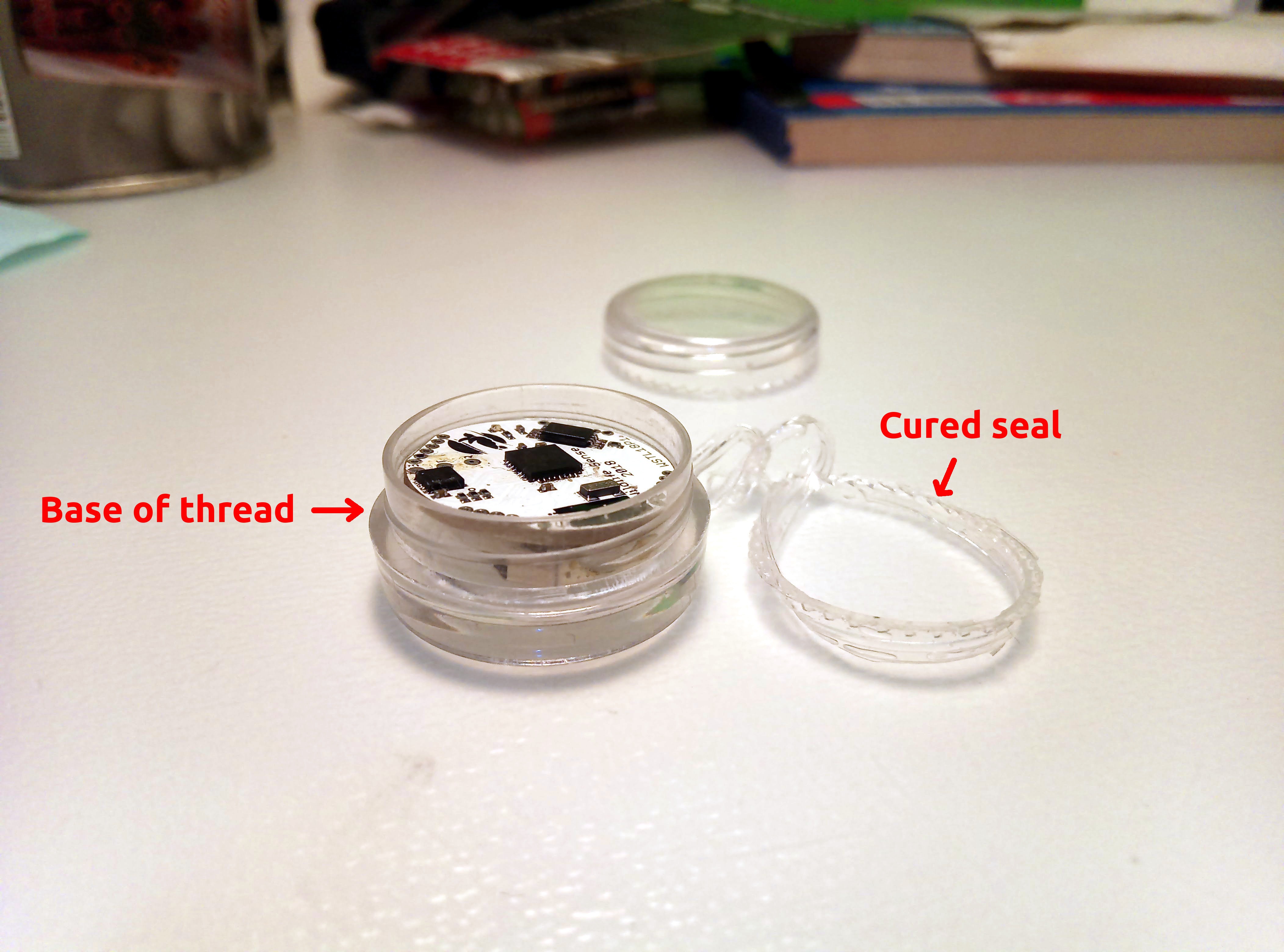
I used low-cost acrylic 3ml jars and planned to seal them with some sealant silicone.
Sealing method 1: Failed
I started with clear silicone placed around the thread on the base part.
![]()
Once the silicone cured, it was ready for deployment. The seal had to be broken at the end of logger deployment, but the case could be re-used.
I used this method on the first six loggers, which I tested for a few days at 32cm depth in one of the local beaches. Just a few days later, I went back and retrieved the loggers.
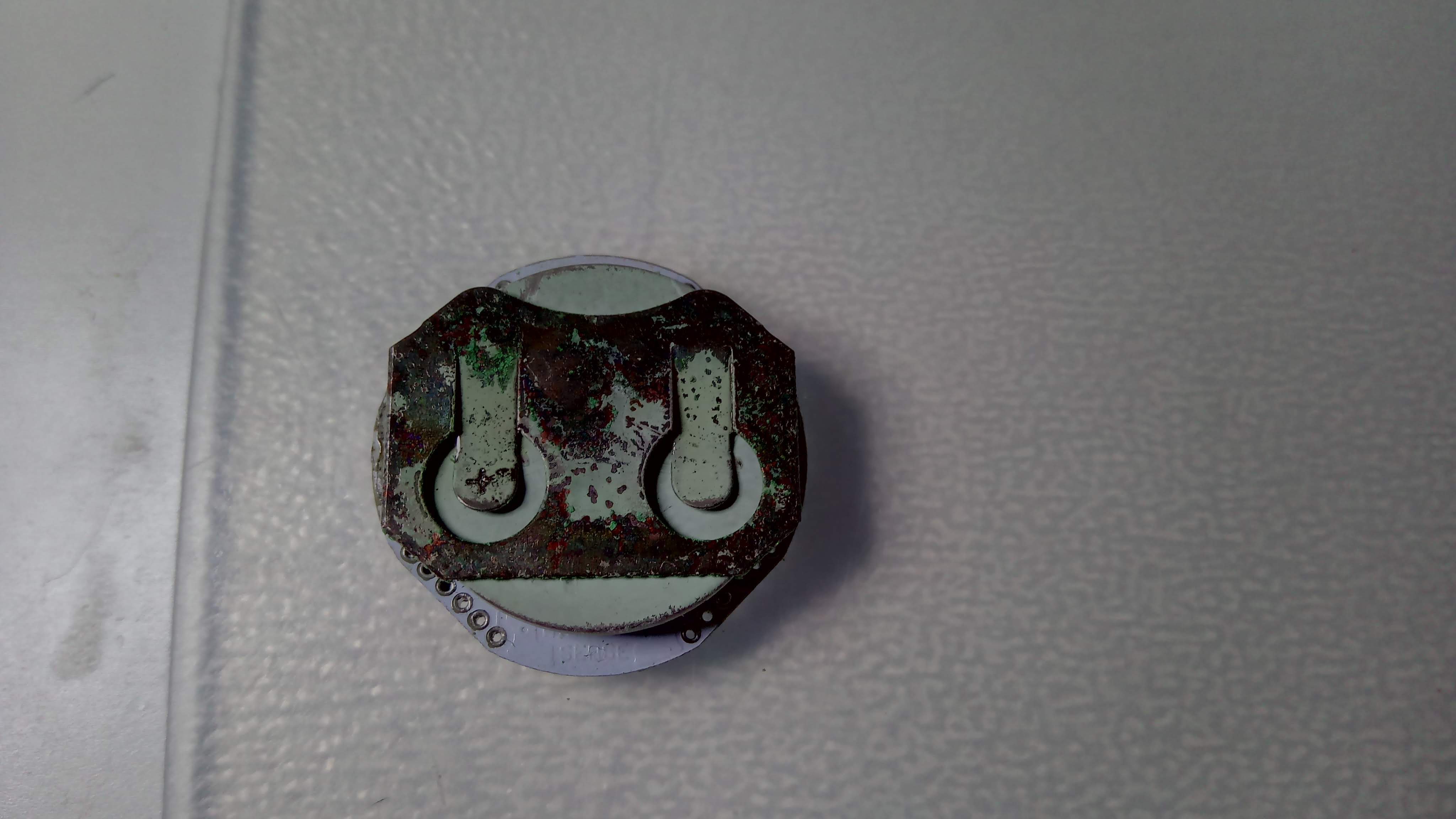
Five of the six loggers survived the initial test. The sixth one also worked but had stopped logging. All loggers showed some signs of corrosion but the limited time, just a few days, didn't allow the corrosion to progress.
This photo is from one of the loggers above that was re-used and had accumulated more corrosion:
![]()
In this short-time deployment, the uart pogo-pin connector functioned without problems.
Sealing method 2: Failed
Using clear silicone to seal the jars meant that I couldn't see if the seal was complete or had any gaps. So I transitioned to black silicone and placed it at the top of the thread, between the base and the lid parts of the jar.
![]() This sealing method initially felt better. Indeed the corrosion on some of the loggers was a bit more limited, but a new problem emerged: When the loggers were retrieved and I tried to download data, I found a thin but persistent film of sealant on the pogo-pin pads at the top side of the boards. This made control and data download very difficult. In some cases I had to scratch the pads to remove the sealant, while in others I had to make contact at the perimeter of the pad which only worked after many attempts.
This sealing method initially felt better. Indeed the corrosion on some of the loggers was a bit more limited, but a new problem emerged: When the loggers were retrieved and I tried to download data, I found a thin but persistent film of sealant on the pogo-pin pads at the top side of the boards. This made control and data download very difficult. In some cases I had to scratch the pads to remove the sealant, while in others I had to make contact at the perimeter of the pad which only worked after many attempts.![]()
The thin sealant layer is hard to see in this photo. Alcohol, contact cleaner, or nail polish remover didn't help at all, only persistent mechanical force helped just enough to download the data.
With this method, all loggers had some corrosion on the battery holder, which was at the lower part of the case, but worked until retrieval after several weeks in very wet sand. Still, the contact insulation problem meant I had to return to clear silicone.
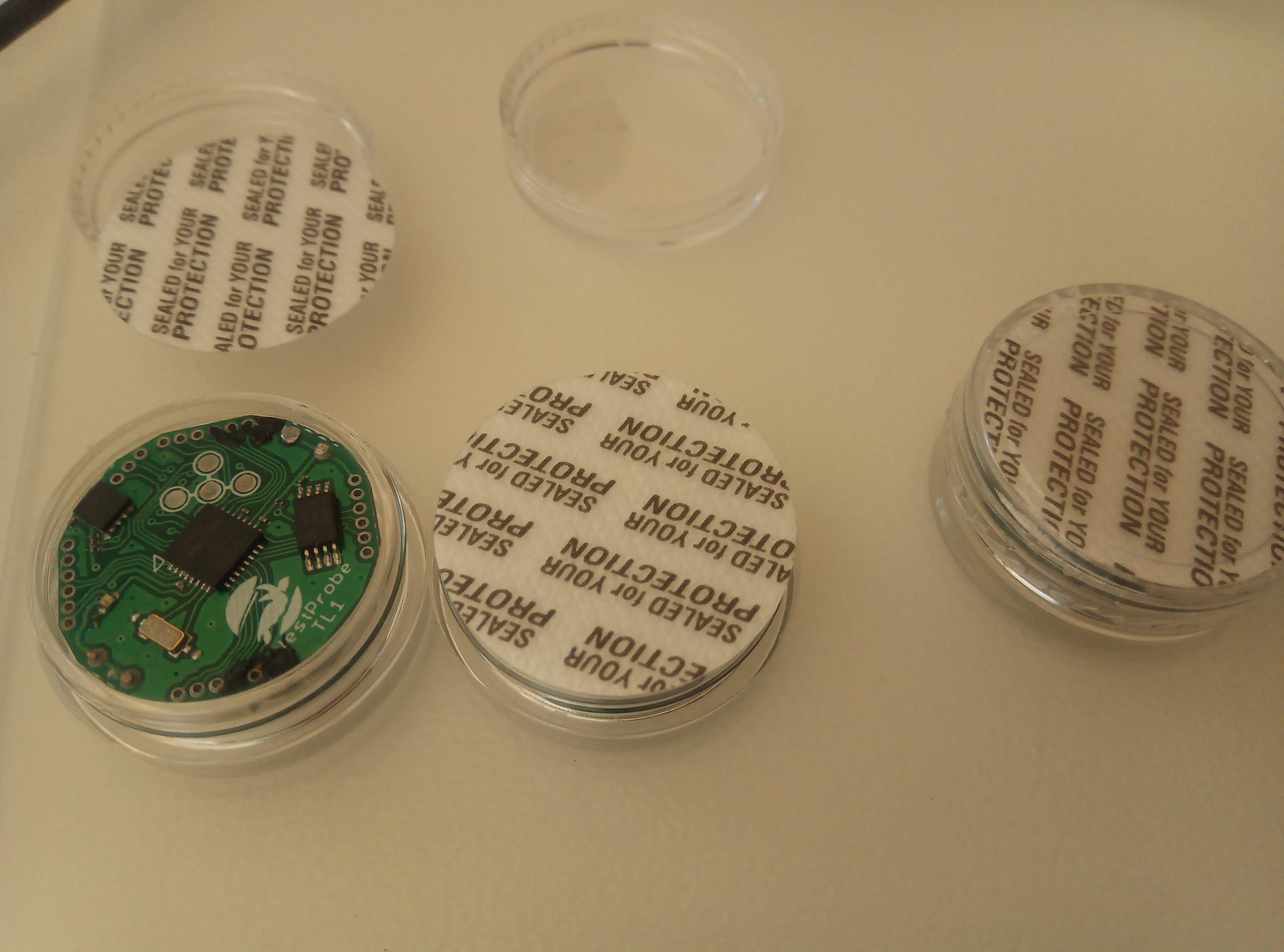
Sealing method 3: Perhaps...
For the third method, I was able to find circular pads that are used to seal these specific cases. The seal is not meant to be water-tight, so still had to add silicone around the screw-cap thread.
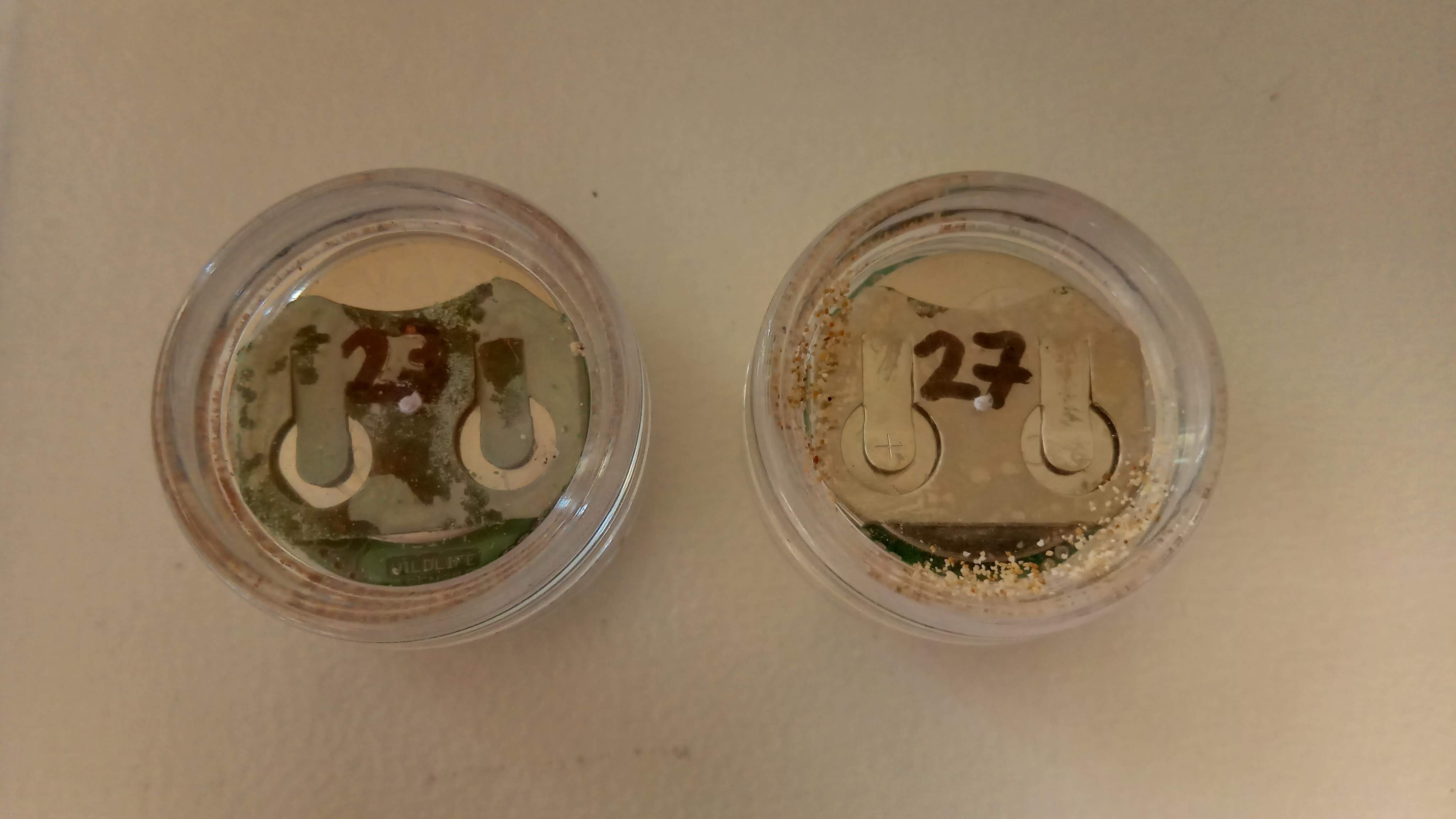
![]()
This is how two loggers looked after retrieval. Number 23 had been used previously and was already corroded, so only number 27 was new.
![]()
I still had a small deposition on the contact pads.
![]()
This caused limited problems on control and data download. I could use it ok, but wouldn't release this to "regular" users.
It's not a sealed deal ...
I'm pretty sure there is a limited leak of salty moisture into the logger case. At this point I'm not prepared to move to a custom molded solution, so I'll stick with method 3 with some extra method to strengthen the seal. With the nesting season over, I have all winter to work on this.
-
TL1 in a sea turtle nest
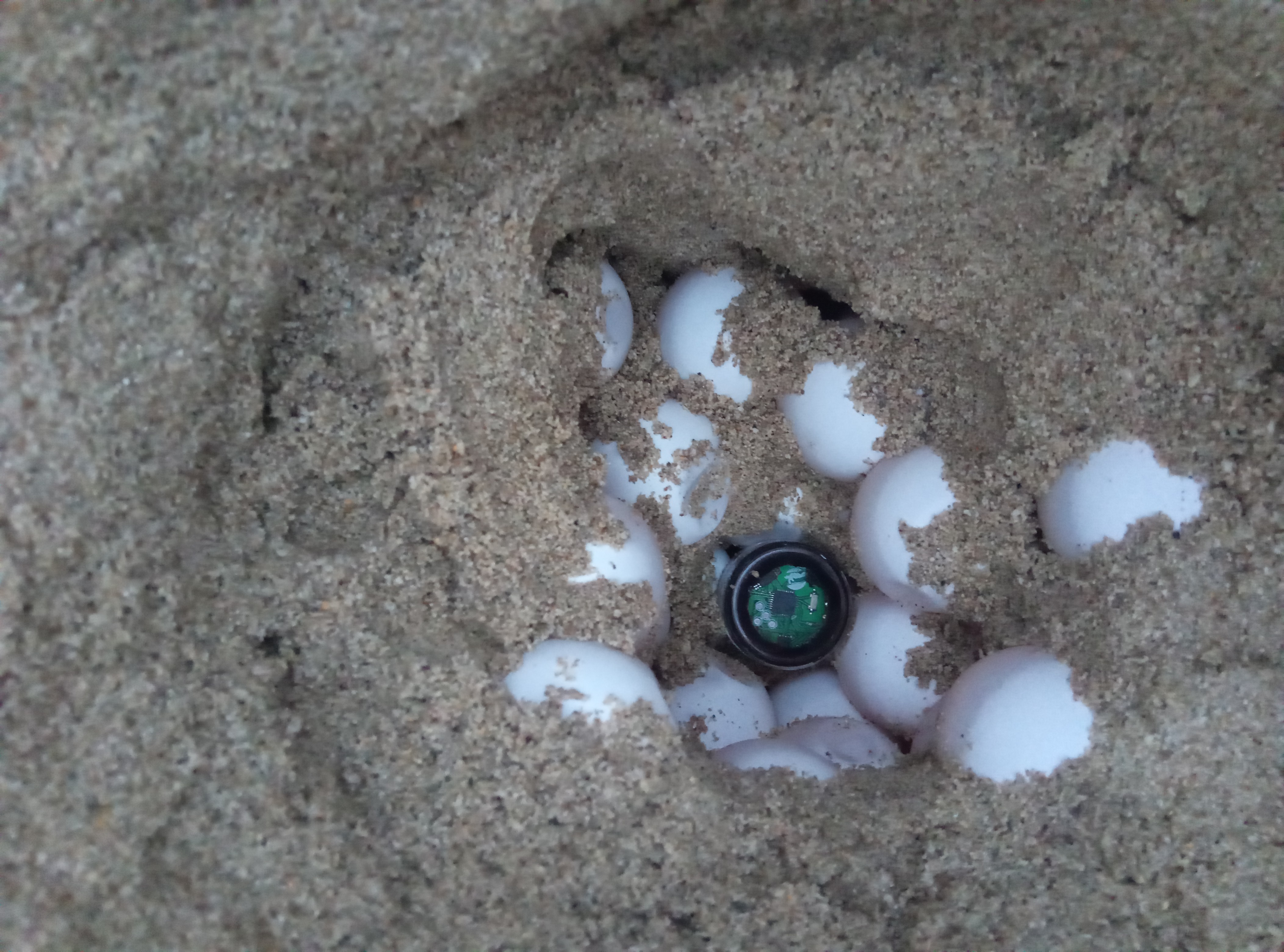
06/25/2018 at 01:11 • 1 commentNote: this research is done under research permit issued by the Ministry of Environment and Energy of Greece and is fully supervised.
Sea turtle nesting started more than a month ago, and we've already placed 16 temperature loggers to record temperature every 10 minutes at the center of a selection of nests.
![]()
The motivation behind this research is to investigate whether this population is affected with elevated temperatures caused by climate change. Elevated temperatures can heavily skew hatchling sex ratios to female and cause reduced fitness and therefore high mortality after hatching.
A sample of emerging hatchlings will be intercepted and tested for fitness. Crawling, righting, and swimming speeds will be compared to incubation temperatures. Similar research has been done before, but the logger's low cost allows a much larger sample, while its extendability opens options to control nest incubation temperature at their natural location.
-
Product ready
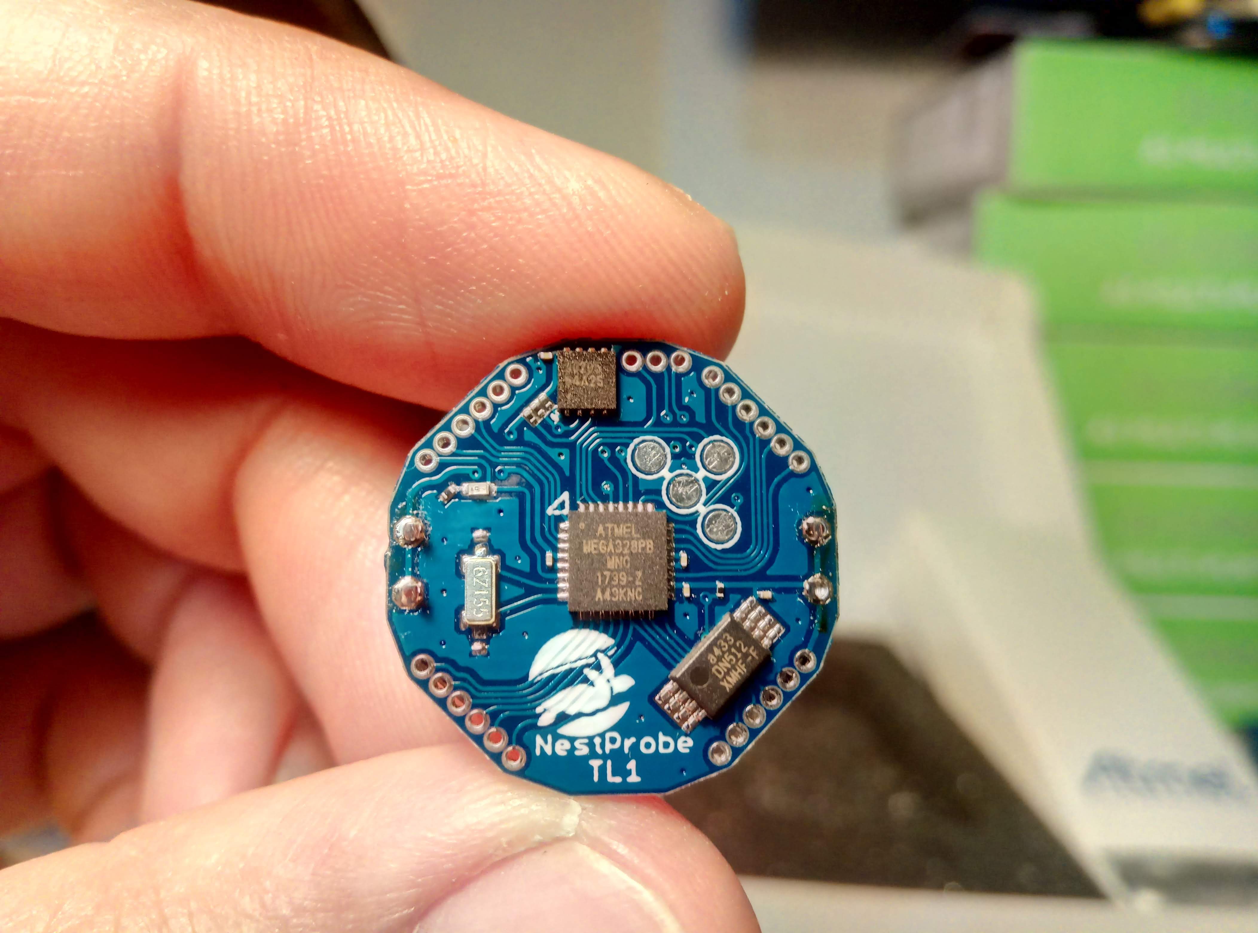
05/25/2018 at 22:19 • 3 commentsThere's many photos, videos, and updates I've skipped due to a very hard deadline (turtle nesting season) combined with a happy family occasion that involves sleep deprivation, but this isn't one to miss: The final product made, copy 1 of 50:
![]()
I've been through 3 prototypes to get here.
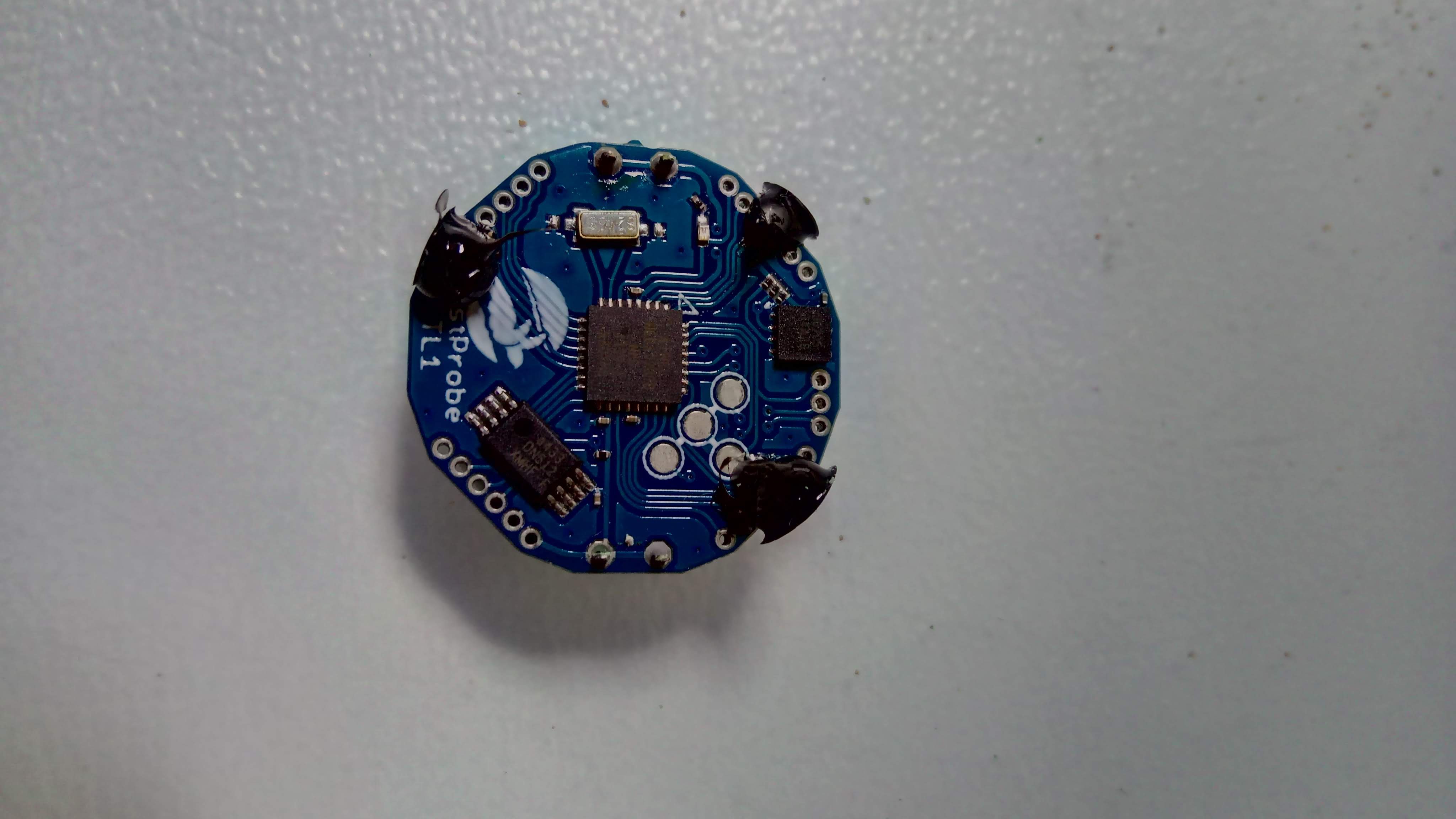
P1 was functional but I hadn't made up my low-power connector so the only viable communication was the LED. Not very good for development, but I still have one blinking on my desk.
P2 was fully functional, and I made 6 copies of it, which I used for extensive and exhaustive testing. One of them had humidity leaked into the case, which taught me to use black silicone instead of clear, so I can see the seal is good. It kept working after reset, but was later crushed by accident (desk-chair wheel) and I assume is not functional. Another lost its battery holder (I had already moved the next design to stronger through-hole instead of SMD), one is logging on my desk for verification of battery life expectancy, one has connectivity issues (I improved the connector in P3), and two of them are currently logging inside a sea turtle nest and I expect full data recovery upon retrieval. I needed some physical improvements such as routing, MCU pin breakout, manufacturing convenience etc.
P3 implemented them but needed work on the stencil layer. I tried a different manufacturer (for learning purposes), and found that tight soldermask margins can lead to bleaching over pads. I didn't even assemble one of those. I also learned that white soldermask makes it hard to inspect routing and pads and is too bright for close-up photos.
P4 is the one seen above, and is the final product. I moved all passives to 0204 to make tight tracing easier and all signal traces are 6 mil, which pushes the low-cost PCB prototyping specs of most PCB manufacturers. I added a soldermask margin around the MCU's pads and widened the 0204 stencil openings so the solder stays on the board. I've also broken every single pin except the two for the crystal oscillator out to the perimeter headers, so this board is completely extendable. It's worked flawlessly for home stencil-skillet assembly.
I apologize for the GitHub currently being empty, I had planned to reorganize it and haven't had the time to. If anyone wants to start making these, just shoot me a message.
By the way, I also renamed this temperature logger to NestProbe TL1, with NestProbe being a series of planned scientific research devices and TL1 the model number.
TL2 (next year) will use ATtiny814 and no external crystal, and will aim for a $4 BOM.
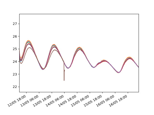
Here's a plot of a beach trial run. I placed six P2 loggers together at 32cm depth. You can see where number 5 stopped due to humidity in the case - the humidity evaporated into the case and made it cooler for a while before the logger stopped.
![]()
-
A UART connector for low power designs
04/01/2018 at 19:16 • 1 commentLow power devices try to keep all unused peripherals switched off. Even the simplest peripherals, such as UART, can shave months or years off battery life on devices powered by a coin cell if a 'UART receive' interrupt is active. If it isn't, how can the device know when it is connected to another device so it can power the UART up?
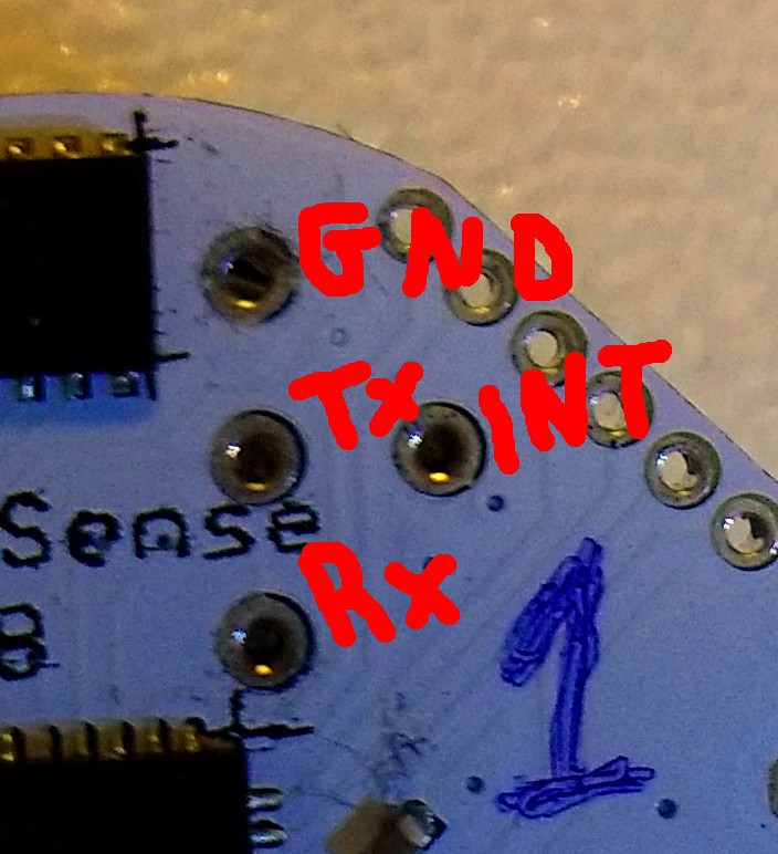
I've come up with a simple, low-cost solution (I'm sure not the first): Add one more wire (INT) to UART's three wires (Rx, Tx, and GND). The MCU keeps this wire at a high state via its internal pull-up resistor. The connector shorts it to GND, which is how the MCU can tell it's connected and initiates data exchange. The device can check that pin's state at regular intervals, e.g. every time the RTC interrupt fires, or in less power consumption-wary schemes it can use a pin interrupt.
![]()
The four wires are arranged it a 'T' formation to eliminate orientation confusion; there's only one obvious way to connect it. For now I'm using an FTDI-based USB to UART bridge board I got off ebay, with four pogo-pins soldered on a piece of stripboard.
![]()
Everyone wishing to use even one of these temperature loggers will need this USB-to-UART-to-T-shape connector, so I plan to make an all-in-one PCB to include in this project's schematics.
With this connector, I'm comfortably achieving a 1M baud connection. This speed is necessary because the device may need to send up to 64kBytes of data to the host, and this has to be achieved well within the 8 seconds between each Real Time Counter interrupts.
-
First temperature log
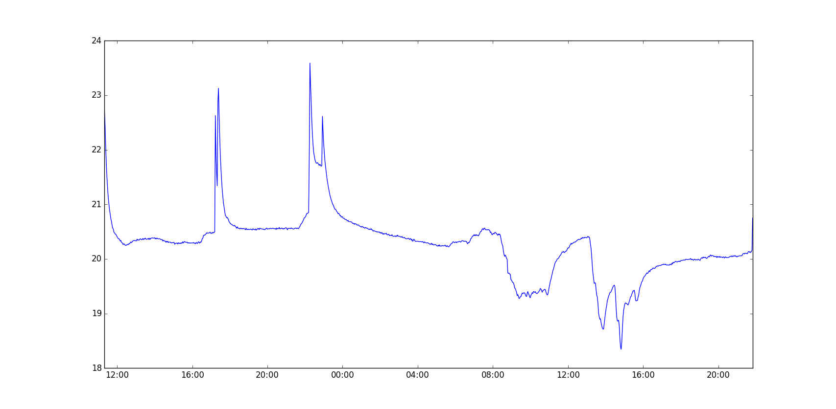
03/14/2018 at 22:13 • 0 comments![]()
Here is the first day-long plus temperature log. X axis is clock time (UTC) and Y axis is temperature in °C. The spikes on the left are from holding the logger and the drops on the right are from opening the window.
The data are extracted via uart by a python script and the plot is made by another python script, so it's all python on the desktop and all of these are/will be on the project's Github. Input, advice, feature requests from anyone with temperature logger experience or not are welcome!
I've placed the logger outside and will publish another plot around the end of next week.
I'll probably be working on this project for another year or so - this is just an early taste.
-
Measuring VCC - why bother?
03/13/2018 at 11:08 • 1 commentAt the time, it was a why-not decision. I didn't need to use the AVR's analog to digital converter (adc). I thought that was a waste, but had read about its ability to measure VCC. All I had to do was connect the battery to AVCC with a decoupling capacitor, which one should do anyway for stability, but also connect a decoupling capacitor to AREF (ADC reference).
This design allows the adc to use VCC or the 1.1V internal bandgap as a reference, but you can also set the 1.1V bandgap as an input channel while using VCC as the reference. This configuration allows one to calculate VCC:
VCC = 1.1V * 1024 / ADC
Why is this important for a temperature logger? What can it do if the voltage goes low? Can't you just use the brown-out detector?
For scientific research there's a real reason to measure voltage and flag when it goes below a threshold. The MAX30205 sensor has a close-to 0.1°C accuracy, but only for VCC between 2.7V and 3.3V. Below that, measurements become less accurate, so it's important to know if and when the voltage dropped below that threshold.
Given the logger's consumption, this shouldn't happen for at least 6 months, but having verification by the firmware is a bonus!
-
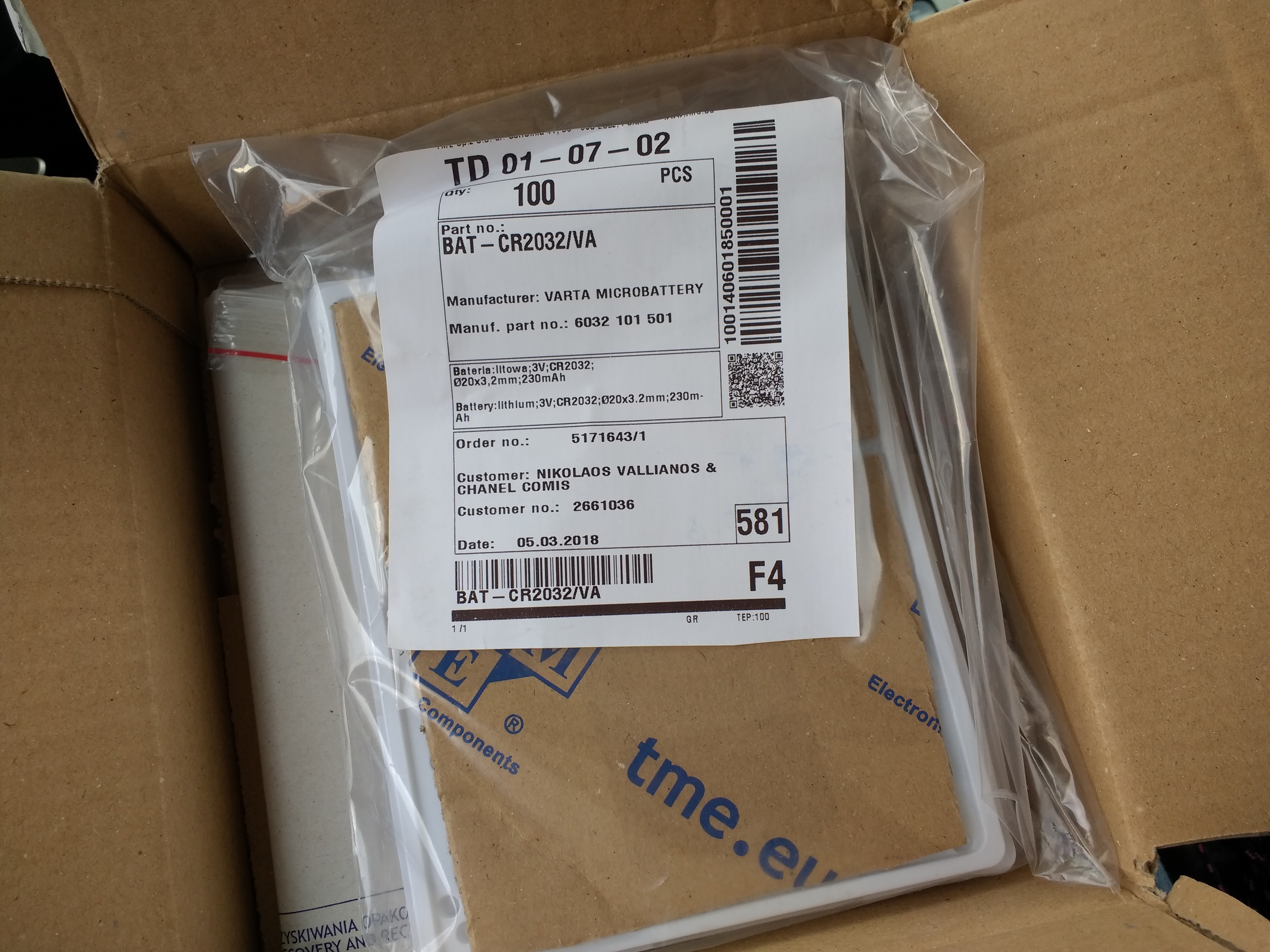
100 batteries arrived
03/13/2018 at 09:02 • 2 commentsOne of the sweetest aspects of using a CR2032 battery is the price you can get them for. Sure they're a couple of euros/bucks at the local store, but because of their popularity you can get a sweet deal from distributors.
Because of their fire hazard (technically) serious distributors will only ground-ship them, so my best, and as it turned out quite good, option for Greece was tme.eu . I got 100 batteries for just €23 plus €7 for ground shipping.
![]()
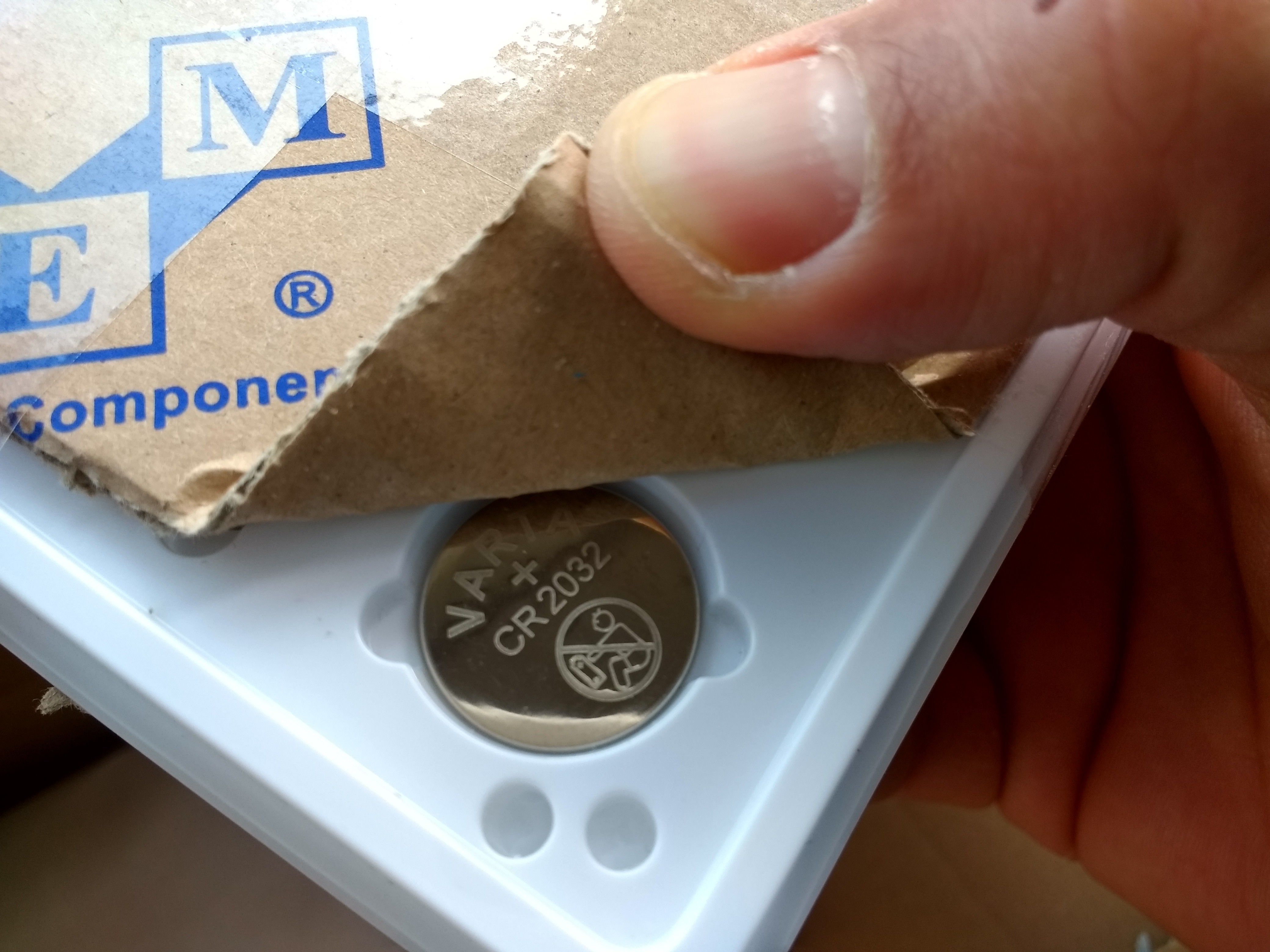
Not bad for a bunch of Varta coin cells that should each run a logger for more than a year, and Panasonic or Energizers aren't far off.
Mind you, I also bought a bunch of no-name coin cells off eBay a couple of years ago, but most of them were discharged even before I used them. To be fair, bad storage on my end was partly to blame for that.
![]()
I'm looking forward to start deploying these with the loggers pretty soon!
-
Last prototype ... I hope!
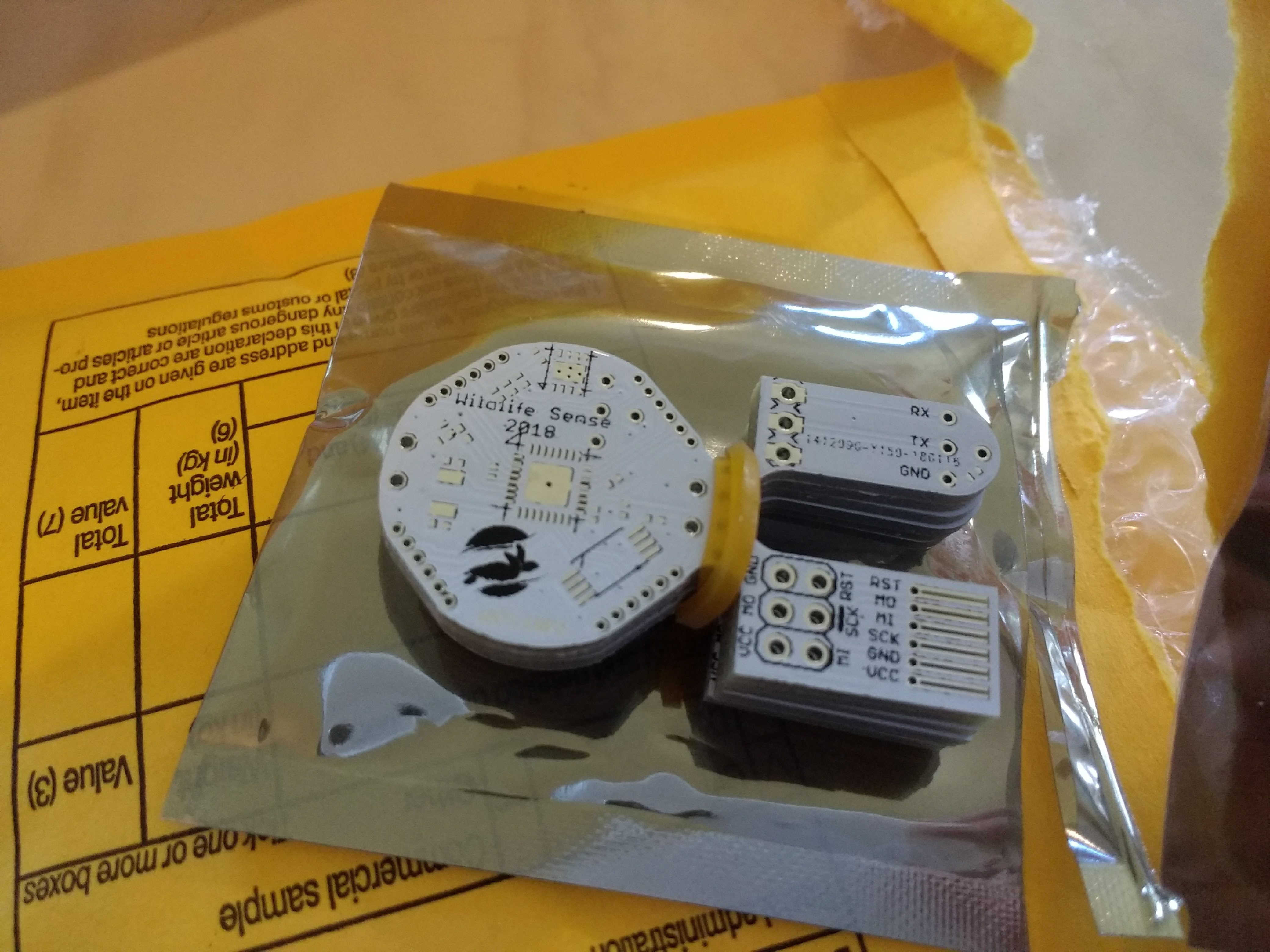
03/10/2018 at 15:19 • 0 commentsA while ago I got a small batch of the second prototype's PCBs (many thanks to Zequing of Makerfabs).
![]()
This version was a special Gerber I made to include the temperature logger's board (left), an AVR in-system programming connector adapter (bottom right), and a uart connector meant to be used with surface-mount spring-loaded connectors (top right).
Changes between prototype 1 and prototype 2
The main difference between the first and the second prototype designs is that the uart connector includes one more line, which is only used to short a pin to ground so the firmware knows when it's connected and can initiate a transaction. I don't even use an interrupt for that; the firmware just checks whether that pin is high (unconnected) or low (connected) every time it's woken up by the real-time counter. This scheme is a bit boring but saves quite a bit of power.
This design can use both the surface-mount and the through-hole versions of the CR2032 battery holder by Linx. This allows me to use already-purchased surface-mount uints, but in the future I'd prefer the through-hole because of added mechanical stressed caused by pressing the battery holder to hold the device.
Other changes include a change in the LED's location and the exposure of the I2C lines on the headers around the PCB.
I also changed every component's stencil footprint. I use a steel stencil, and the first prototype had lots of solder knees and bridges. The second prototype, with a stencil opening of half the area for each pad, looks much better with no bridges at all. Everything worked on the first attempt. Below is the first unit cooking on the skillet.
![]()
Connecting to a PC
Although I added the uart connectors to the design, I haven't actually used them because I didn't add the spring-loaded smd connectors needed to my last order. Instead, I used a piece of stripboard and some generic pogo-pins, along with a 3.3V USB to uart device using FTDI's FT232. In the (not so distant) future, I plan to design a usb-to-serial board complete with pogo pins that you can hold like a pen.
![]()
For now I'm using the serial adaptor's 3.3V output during firmware development.
Low-cost/power/size temperature logger
A low cost ultra-low-power small-sized high accuracy temperature logger for use in scientific research.