Nikos
Nikos-
The (very) basics of bootloader development
02/10/2018 at 11:30 • 0 commentsA temperature logger is a classic example where in-field firmware updates should be an option. I don't particularly plan to add functionality, but users should be able to use the (UART) data cable instead of a development environment and in-system programming to receive bug fixes and optimizations.
I started reading about bootloaders and very quickly got a headache. The ATmega328PB datasheet has a bootloader chapter, and Atmel has released an AES-encrypted bootloader example specifically for this device. I didn't care about encryption, since this is an open-source project, but I thought I'd learn something... more headaches.
After watching some youtube videos that mostly didn't explain the basic context, I luckily came upon a pdf put together by the AVR Freaks community a while back (found here at the bottom of the first entry) and finally got it.
These are the three points I wish I had read first to make sense of all the other details:
- A bootloader is a regular firmware program and it's best developed as a stand-alone application. It should be small enough to fit in the bootloader section
- You need to set your programming environment to enable the bootloader section and put this application in that section. You can also use fuses to protect it.
- An mcu with a bootloader technically has two firmwares. It first runs the bootloader (hence the name)[Edit: depending on the fuse, the AVR starts at main program or at the bootloader, but if you set the fuse and there's no bootloader it will go to the main program, which is nicely forgiving]. Then your main application will run. If you want to, you can program your bootloader to be able to receive a firmware file and write it to the main application flash memory. The main application should be able to reset back to the bootloader to enable a firmware update, unless your device has a reset button.
I think I've got these basics right. The next step, overwriting the flash, seems easier to grasp.
-
Program to download logger data
01/28/2018 at 14:14 • 1 commentAny data logger is useless without an easy way to download recorded data. I'm considering the hardware design complete (for this model), so from now on I'm focusing on writing the firmware. In parallel, I'm writing a host computer program (python script) to setup the loggers before deployment and to download data in a usable format after deployment is complete. The script is available at the project's github. By necessity, I'm also developing the protocol of communication and data download, since I'm not aware of any standard or any open protocol used by already established software.
Anyone with knowledge of an existing protocol or interested to help out, please let me know and I'll be happy to work together or utilize any advice.
-
Ultra-low consumption reached
01/26/2018 at 08:48 • 0 commentsI can happily report that the WSTL18 temperature logger can achieve its power consumption target. I had previously calculated a datasheet-based target consumption of 3.22uA during power-save mode, with the real-time counter running. I've currently achieved a power consumption of 2.92uA during power-save. I've already established communication with the temperature sensor and memory chip, and can verify they are operational and can successfully enter their lowest power-save mode.
![]()
This measurement was taken at 3.3V coming from the uart adaptor, and was taken with a simple multimeter, so I don't expect it to be very accurate. I also expect the power consumption to be slightly lower at 2.7-3.1V from the coin-cell battery but higher at 30°C in an incubating sea turtle nest.
Total power consumption
Power consumption goes up to slightly under 5mA when all chips and a couple of mcu peripherals are on, but this only lasts for under 0.1 seconds. I'll add another 0.1 seconds for every 10-minute log, because the mcu has to wake up every 8 seconds (75 times per 10 minutes) and check if it's been ten minutes. I'll round it up to 1 second per log, so 6 seconds per hour just to be sure. So in one hour, the device has consumed 3uA + 5mA* ( 6 seconds /3600 seconds/hour) = 11.33uA. I'll round this up to 20uA.
How much juice is in the battery?
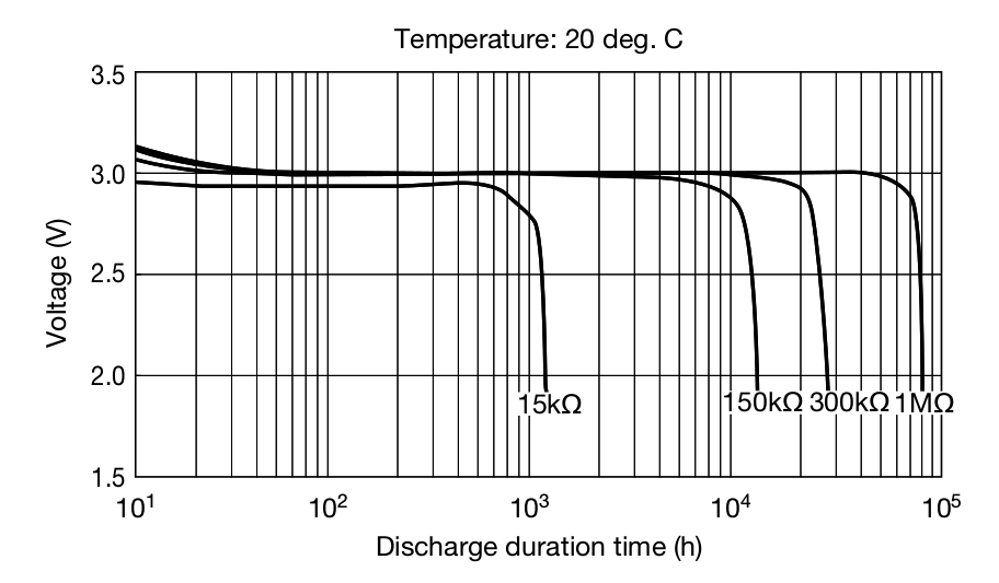
Most brand-name CR2032 batteries report a total capacity between 200mA and 240mA. It's important to notice that this is the capacity the battery can give until its voltage drops to 2V. Luckily, coin cell batteries maintain their voltage until shortly before they die, so the total capacity isn't reduced much for lower voltage drops. The ATmega328PB can operate at that voltage, but the memory chip needs 2.3V and the temperature sensor needs at least 2.7V. The temperature sensor won't give any warning, but instead its temperature readings will become widely inaccurate. I'd rather stop recording temperatures when the voltage reaches 2.75V. When will this happen?
![]()
A power consumption of 20uA is roughly equivalent to 150kΩ load at 3V. According to Maxell's CR2032 datasheet, this should give more than 10000 hours of operation before the battery voltage starts dropping close to 2.8V. I don't expect the short high-consumption pulses to affect that by much. That's equal to 416 days, which is well over my original target of 180 days.
Instead of trying to extend the logger's operational time, I'm just going to say that the WSTL18 can safely maintain stated temperature accuracy for 180 days on a new coin-cell battery with a stated capacity of at least 200mA. That's good enough for the salesman.
Battery-Time test
I've actually designed the WSTL18 so that the ATmega328PB can measure the voltage of its power supply using its internal 1.1V reference. A capacitor is connected to the Vref pin, which allows the ADC to use Avcc as the voltage reference to measure the 1.1V refrence. This is a power-expensive operation and I won't have the logger do it during regular logging, but I do plan to have a few loggers run a voltage-time log, which will help verify the logger's stated duration of operation.
-
Design a shield with your next coin-cell project
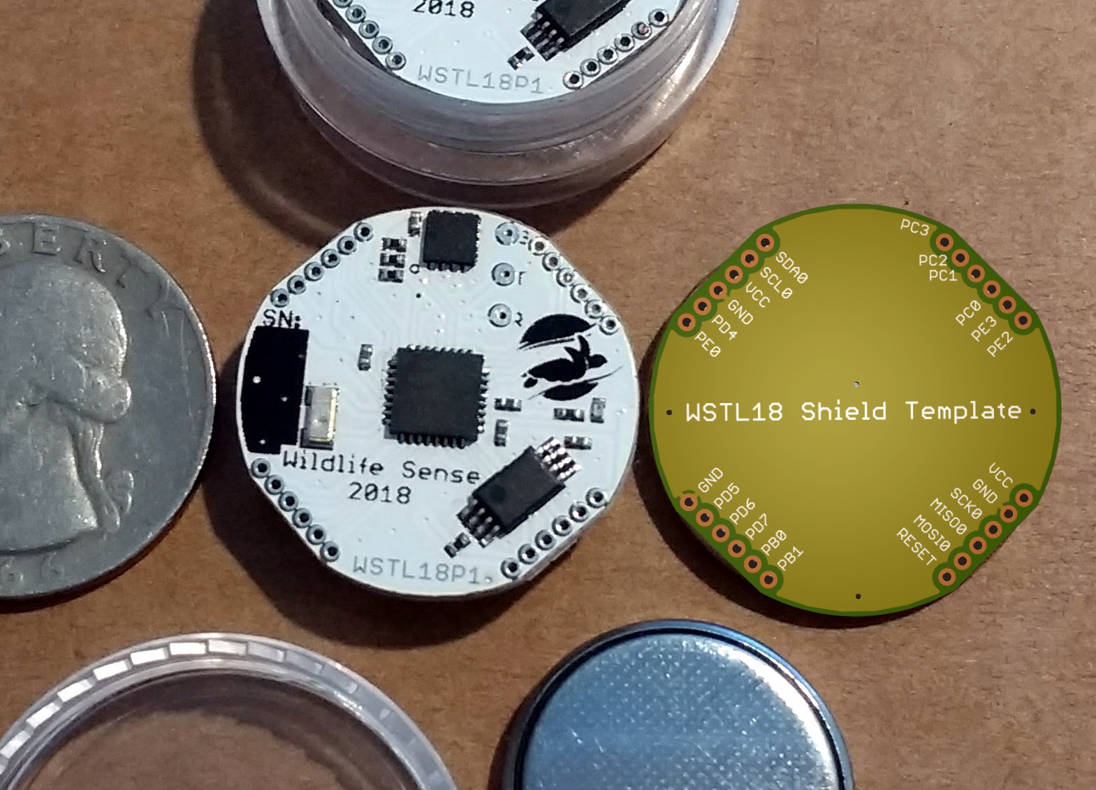
01/08/2018 at 21:31 • 0 commentsThe WSTL18 temperature logger is slightly larger than a CR2032 coin-cell battery. With most of the Atmega328PB's pins broken out to headers around the board's perimeter, it doubles as a coin-cell development board.
To make expansion shield making easier, I've made a template shield with all pins labeled. The entire board plus shield will fit in a readily available 5ml acrylic jar, as long as common-sized components are used. For anything larger, such as a LoRa module or LCD screen, you'll have to find another casing solution.
![]()
The shield includes a milled opening not seen in this rendering, to allow access to the uart connector pads on the WSTL18 below.
The shield template is available in Eagle format on the project's Github (go to Eagle -> WSTL18_SHIELD).
-
In-system programming adaptor
01/08/2018 at 03:57 • 0 commentsThe WSTL18 uses an AVR microcontroller. Its in-system programming interface, whose six wires include the SPI, power lines, and reset. Those have all been broken out to a 6x1 1.27mm header for programming as well as availability of the SPI to any expansion shields.
![]()
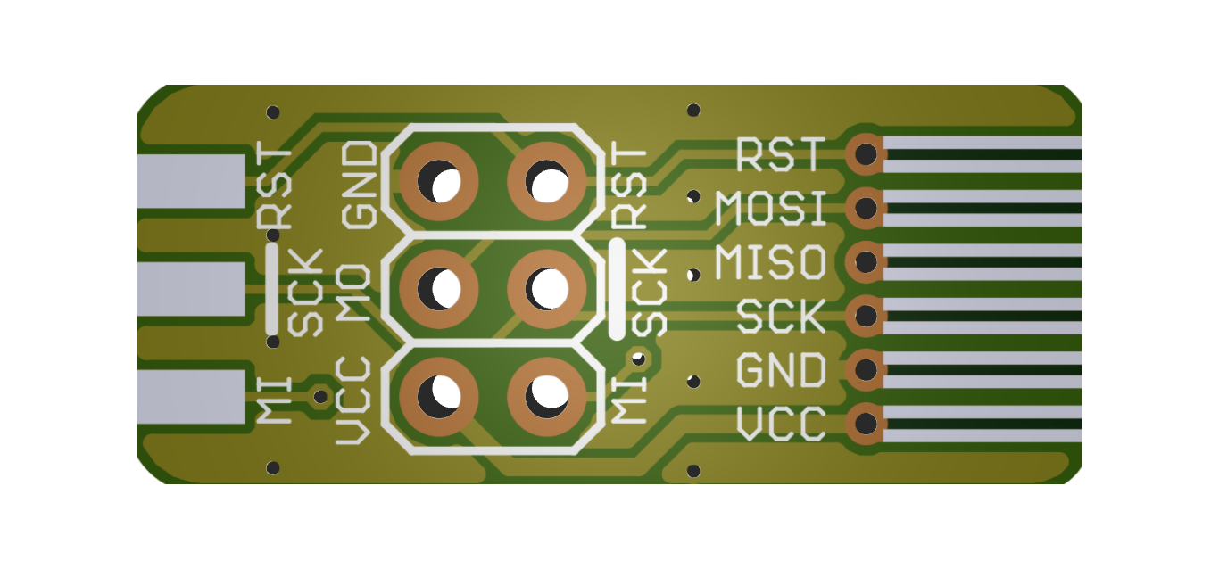
Connecting single-core wires to the headers is ok for code development on a prototype, but not practical at all for (workshop) production programming, so I've designed an adaptor for the regular 2x3 ISP header.
![]()
On the board side, to the right, I placed both a 6x1 1.27mm header as well as long smd pads to solder pogo pins on, something like this but with all six pogos in a row.
On the AVR programmer connector, on the left, I've placed a traditional 2x3 0.1" connector as well as a 0.1" edge connector. This flexibility wasn't required but I've wanted to try these connections for a while, so this was my chance. I've added the eagle files for this on the project's Github ( go to Eagle -> WSTL18_ISP).
-
Prototype coding phase
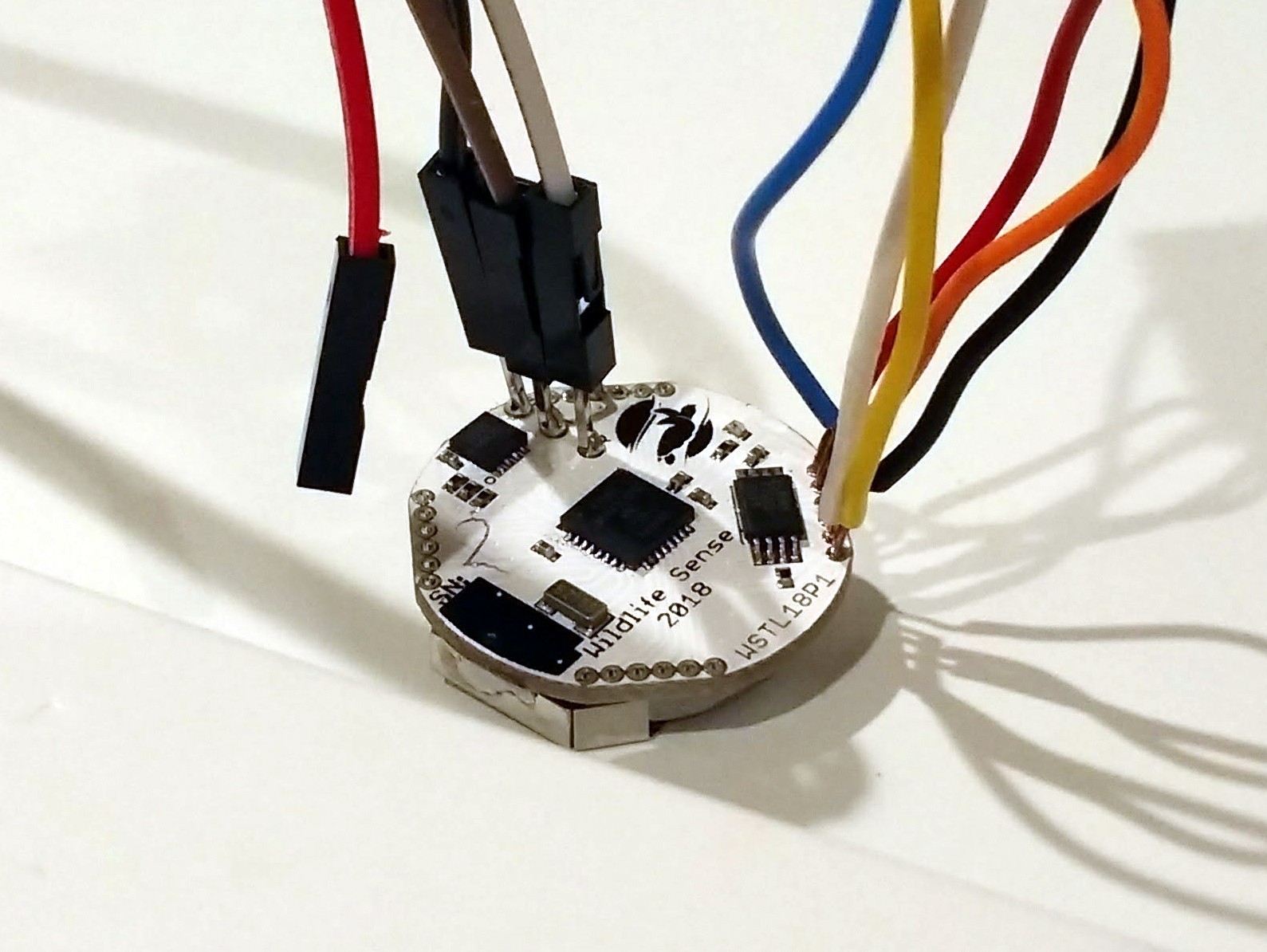
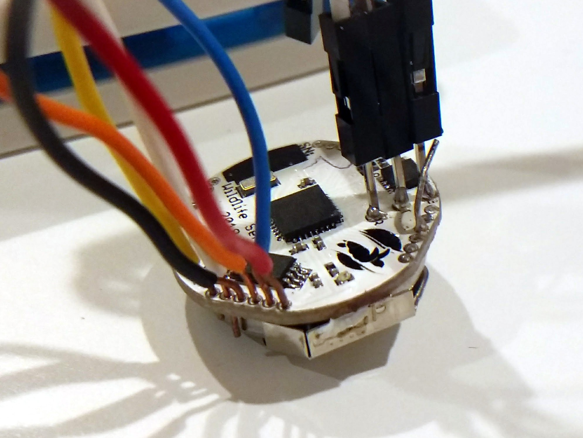
01/07/2018 at 07:52 • 0 comments![]()
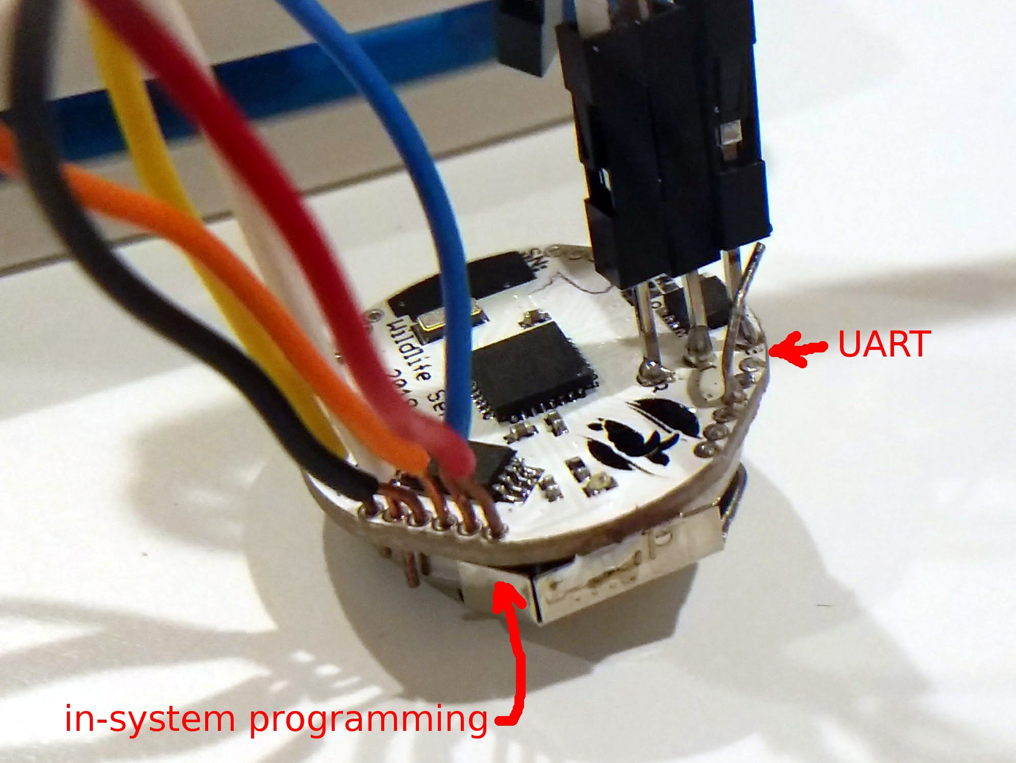
I've now hooked up the temperature logger's AVR ISP cables (right above) to program the device, as well as the uart through an FTDI cable to my computer to test and develop the data exchange protocol with the help of some python code. Of course on a working device this will be done with a special connector, but I'm not making one just yet because the pads have changed between the first and the second prototype designs, but I've only built the first prototype. The code won't need to change much, so this setup is fine for coding. I'm also planning to make the firmware user-updatable through the uart by use of a bootloader, so regular users will only ever need one cable. But that's another story...
![]()
On the right, above, you'll notice a loose cable almost touching the right-most header. I've done this to simulate the fourth connector, which on my designed second prototype will short pin PD2 to ground, allowing the mcu to detect when the uart cable is connected. And that's also another story.
The connector board, firmware, and computer software will all be open-source and added here in due time. There's a long way ahead!
(Check out the Github for the current firmware state and eagle files)
-
Completed second prototype design: WSTL18P2
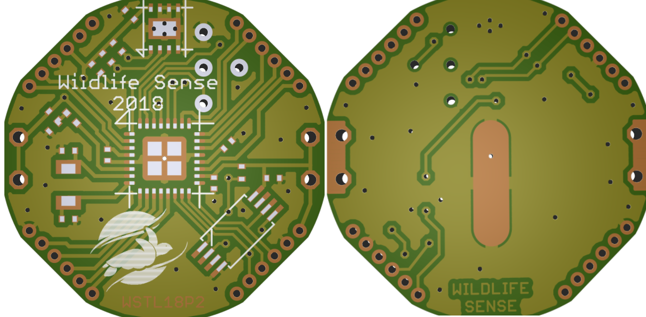
01/05/2018 at 20:57 • 0 commentsAfter applying a few lessons from the first prototype, feedback from this wonderful community, and a few thoughts of my own, I've come to a point where I consider the second prototype of the WSTL18 temperature logger complete. I hope this will be the final design, minus any bug corrections.
![]()
(Many thanks to Mayhew Labs for the free 3D gerber viewer)
I didn't change any components or functionality of the logger. The main correction I made was to make the SMD pad stencil openings (cream layer) smaller because the stencil I made for the first prototype allowed too much solder and caused bridges all over the place, so I had to fix the first assembled board and remove solder from the other two before placing the components on.
Most other changes are related to the headers around the perimeter of the board, the UART connector pads, and the battery holder pads. Here are some of the main changes from the first prototype:
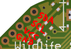
1. The TWI/I2C traces are now accessible via the headers. I also placed a VCC and a GND header right next to them. This will allow adding other sensors or even low-power LCD screens. Bobricius mentioned using this board for a watch and voja wants to make a LoRa expansion shield, so this shield should make expansions like this easier.
![]()
2. I added a fourth pad to the UART connector. This is connected to pin PD3 on the Atmega328PB, which is the INT0 interrupt. That's available in power_save mode, which will allow the uart to be switched off during power_save, allowing further power savings. Notice that the holes on each pad are just holes, not vias. Vias would allow any of these traces to contact the battery on the other side. Holes remove that risk but still allow centering of pogo-pins or even one-side soldering of 0.1" headers. I don't plan to do the last one, but it's an option.
![]()
3. For the battery holder, I added two through-holes on each cathode pad but also left the SMD pads there (right). This allows the use of either the SMD version of the battery holder, which can be machine-assembled, or the through-hole version which can be hand or wave soldered but has a stronger hold on the pcb. I also changed the anode (GND) pad from two near the center of the board to one elongated pad at the center of the board (Left, many thanks to Zequing for this suggestion). The elongation serves to prevent any unwanted contacts while the battery is inserted or removed. That's still much smaller than the battery itself and must be flooded with solder to create a mound slightly higher than the pcb's solder mask
![]()
4. I moved the LED over to the left side of the pcb so it's close to the VCC trace. I've added one more resistor pad after the LED, so now there's one connecting to GND and one to VCC. This allows the user to place one resistor on either pad and place the LED in forward or reverse direction to select if the LED will be HIGH-ON or LOW-ON. The LOW-ON configuration may have a slightly lower current leakage. I haven't tested this claim but if a leakage current difference is there, it will be present at all times so it's worth testing.
![]()
5. I added a 0402 capacitor pad on either side of the RTC crystal. The crystal I selected has very low capacitance so there's no capacitors needed (as far as I understand) but I thought I'd place those capacitor pads there just in case.
6. I disconnected the EEPROM's WP (write protect) and HOLD pins from VCC. Adesto's datasheet specifies these are internally pulled-up to VCC but "whenever possible they should be externally connected to VCC". I went with the disconnect option to simplify the PCB and allow more margin space for the other traces. I don't think this is a noisy enough environment for this choice to cause bugs.
![]()
You'll notice there are no labels on the board. There's just not enough space to add labels without making the board look cluttered.
Eagle cad files are available on the project's Github repo (go to Eagle -> WSTL18P2). Until I get the new PCBs and assemble them, though, the firmware on the same Github repo still assumes the first prototype's LED pin.
-
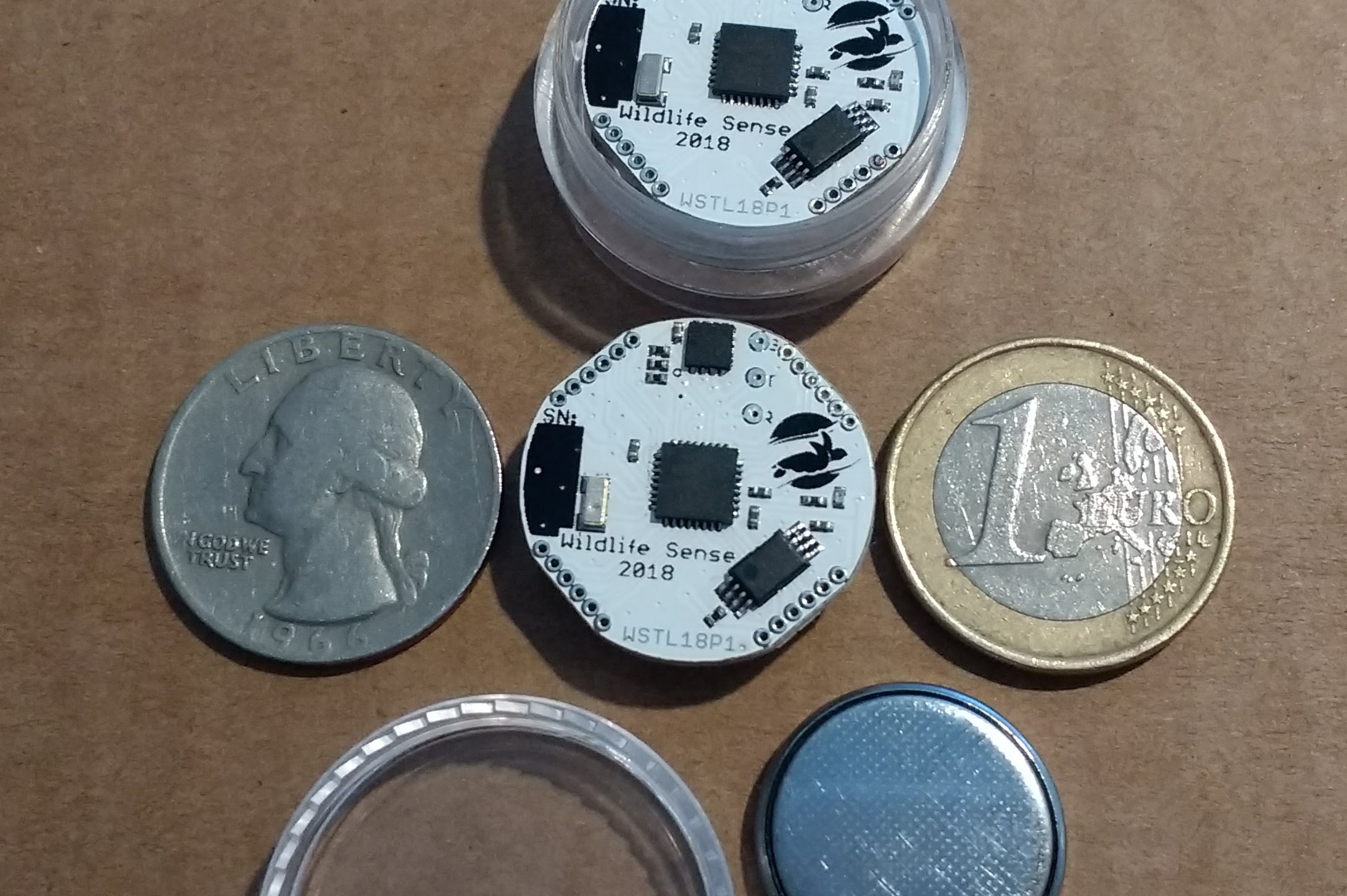
Coin-cell circuit between a Quarter and a Euro
01/04/2018 at 21:53 • 0 commentsI found a quarter laying around, so I thought I'd take a couple of photos for size comparisons. Here's the WSTL18P1 with a quarter on its left, a euro on its right, and the case it's been designed to fit in at the top. The lid and a CR2032 battery are also seen at the bottom.
![]()
With a 0.922 inches diameter, the WSTL18 is just a few mils smaller than a quarter (0.955 inches) and just narrowly larger than a euro (0.915 inches). The next photo gives a closer comparison between a quater (left), a euro (center), and the WSTL18 (right).
![]()
-
Data cable connected awareness vs power consumption
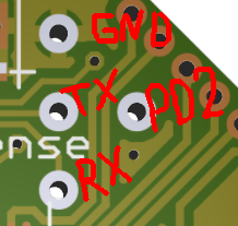
12/22/2017 at 04:34 • 0 commentsOn the first prototype of the WSTL18, I've placed three pads for uart connection. Rx at the bottom, Tx in the middle, and ground at the top.
![]()
But how will the microcontroller know when the cable has been connected so it can listen for commands?
My first thought was to have the uart receive interrupt enabled, so the computer on the other end can just begin sending commands at any time. The problem with that is that uart is not allowed at "power save" mode, which is the lowest power consumption mode that will allow the real time counter to run. So that's out of the window because any higher power mode will kill the battery.
A second thought was that each time the mcu wakes up, which is every eight seconds clocked by the real time counter, it can send out a character over the uart and see if someone will respond. This means that the uart module has to be powered on every eight seconds, which will also reduce battery life, though not as much as the original option.
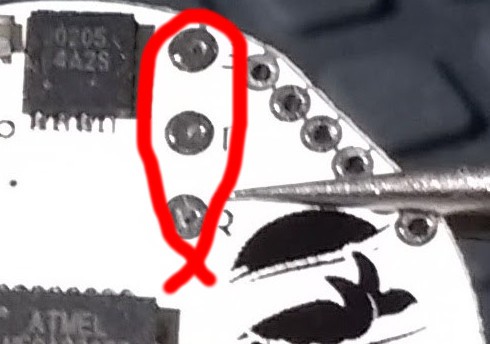
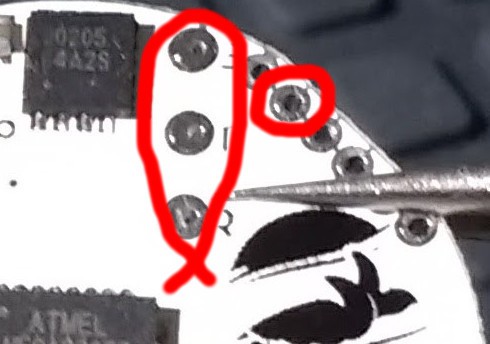
Finally, I decided to use a fourth pad that will make pin PC3 of the AVR available. The pin will be an input with the AVR's internal pull-up enabled. The uart cable connector will have to short this pin to ground. Every eight seconds, the mcu will check pin PC3, and if it is low it will mean a uart cable is connected. The mcu will then send a "ready" character, and the computer on the other end will have a 10ms timeout to send a preset command, such as "begin logging" or "dump all logs", etc.
![]()
This means I'll have to add one more pad connected to PC3 on my next prototype, but for the moment that's available for prototyping on the marked header around the logger's perimeter.
Any thoughts or experience on ultra-low power cable-connected detection please comment below!
-
First prototypes ready, time to start coding
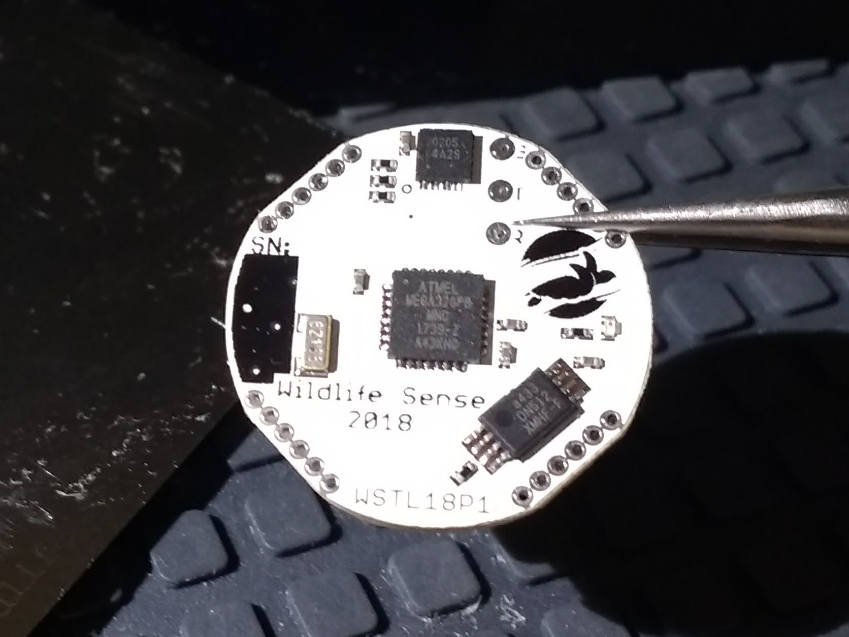
12/13/2017 at 04:47 • 0 commentsI recently received the stencil for WSTL18 from OSHStencils. With only a handful of components I already had waiting on my workbench, I was able to quickly assemble three prototypes.
![]()
The four main components are the microcontroller (Atmega328PB) at the center, temperature sensor (MAX30205MTA+) at the top, non-volatile memory (AT25DN512C) at bottom-right, and real-time counter crystal (ECS-.327-7-34B-C-TR) on the left. The rest are decoupling capacitors, pull-up resistors for I2C, the temperature sensor's interrupt line, and the reset line, a light-emitting diode indicator, and a current-limiting resistor in series with it just under the logo.
A soldering trick for the coin-cell battery holder
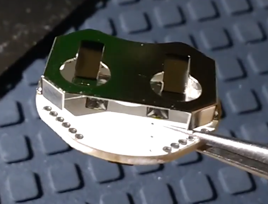
The only component on the back of the PCB is the battery holder.
![]()
The battery holder only connects the positive side of the battery. Lynx, the maker of this battery holder, specifies that almost the entire side of the board under the battery holder should be a flat contact for the negative side of the battery. With a 2-layer PCB, this would make it impossible to make all necessary connections without going around the battery holder area, which would mean the PCB should be much larger than the battery. To avoid this issue, I only designed two narrow strips as battery contacts on the PCB, but flooded them with solder to create a mound and allow a good contact with the battery. The battery rests on the mounds and doesn't contact the rest of the PCB, which is also covered by the solder mask, as long as the vias are covered. The battery holder has to be hand-soldered last. On this prototype I'm using the surface-mount version of this battery holder, but I've already changed the next prototype's design to the through-hole version to ensure a stronger attachment to the PCB.
![]()
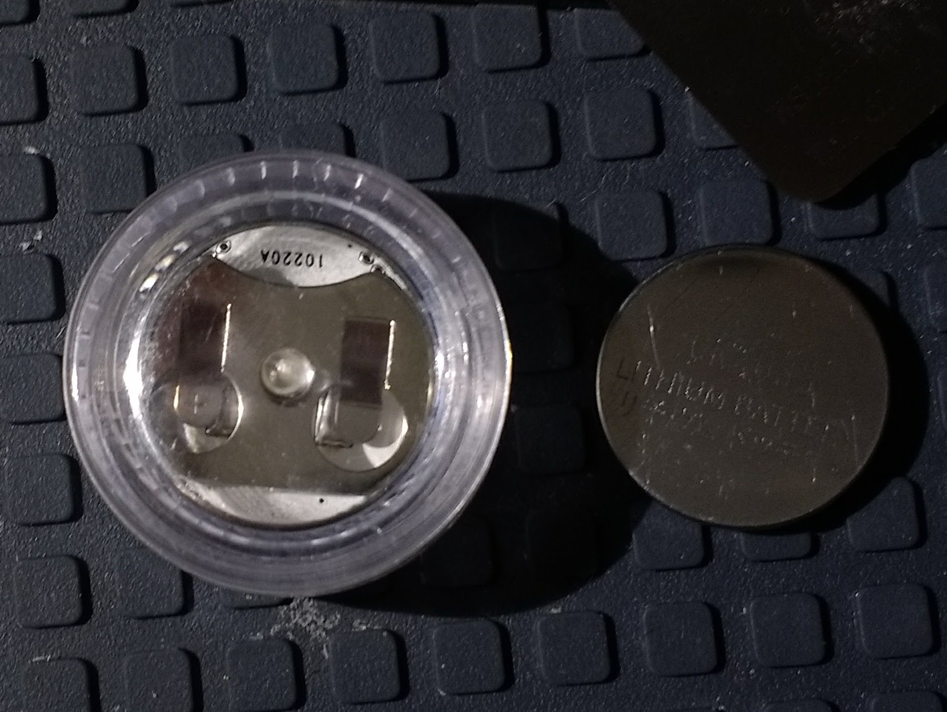
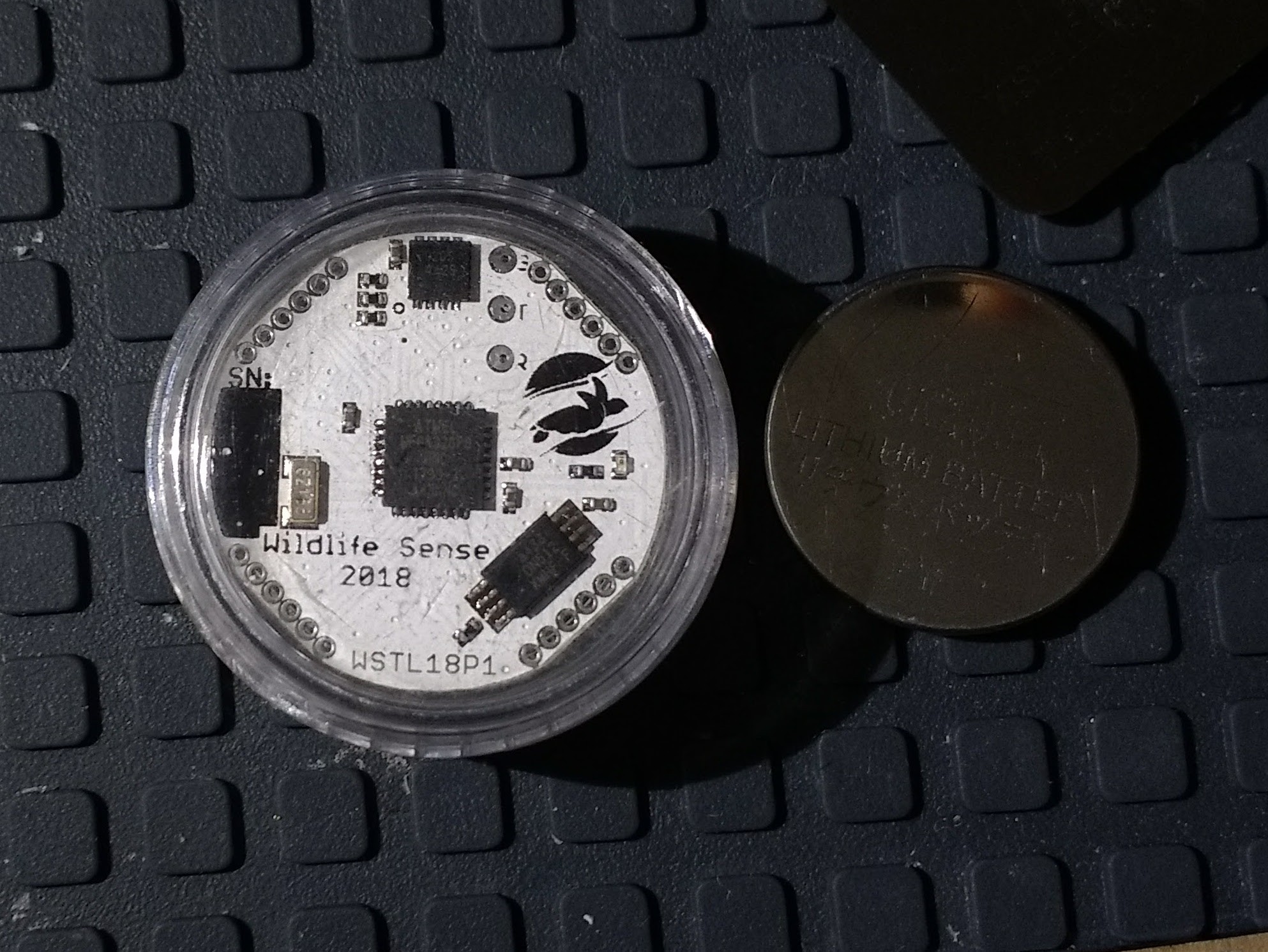
With all components assembled on the board, the WSTL18 fits snugly in a 3ml acrylic screw-cap vase.
![]()
The connectors on the bottom-right are the six AVR in-system programming lines. For now, I'm using six narrow cables to bridge my Atmel-ICE to them. In the long term I plan to create a special connector but may redesign mCU programming options entirely.
I programmed a simple blinking program as an initial check that the board is operational and it's working just fine using the real time counter.
Low-cost/power/size temperature logger
A low cost ultra-low-power small-sized high accuracy temperature logger for use in scientific research.