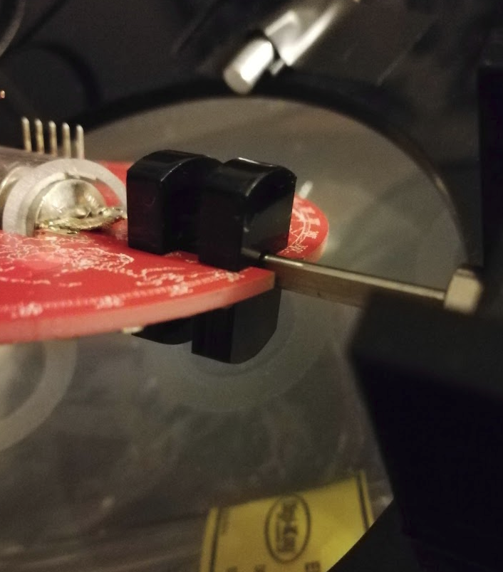
Sliced the interfering part of the shaft couplers off, and put it all back together.

There really only is a tiny sliver of acrylic holding it all together, now. I'd like to take some of my aluminum shaft collars and put a slit down either side to hold the PCB instead, but that's a more complicated setup than the lasercut acrylic, for now.
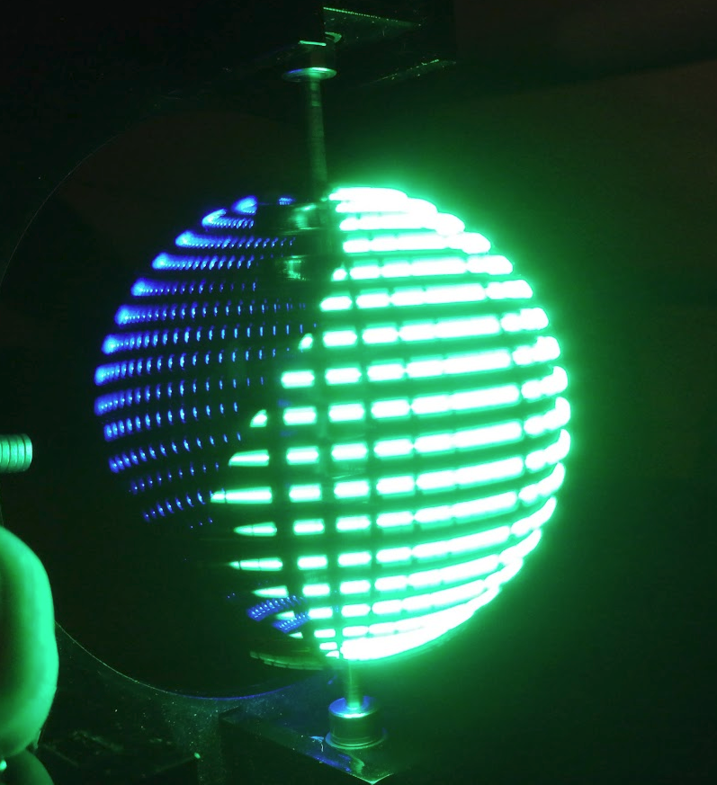
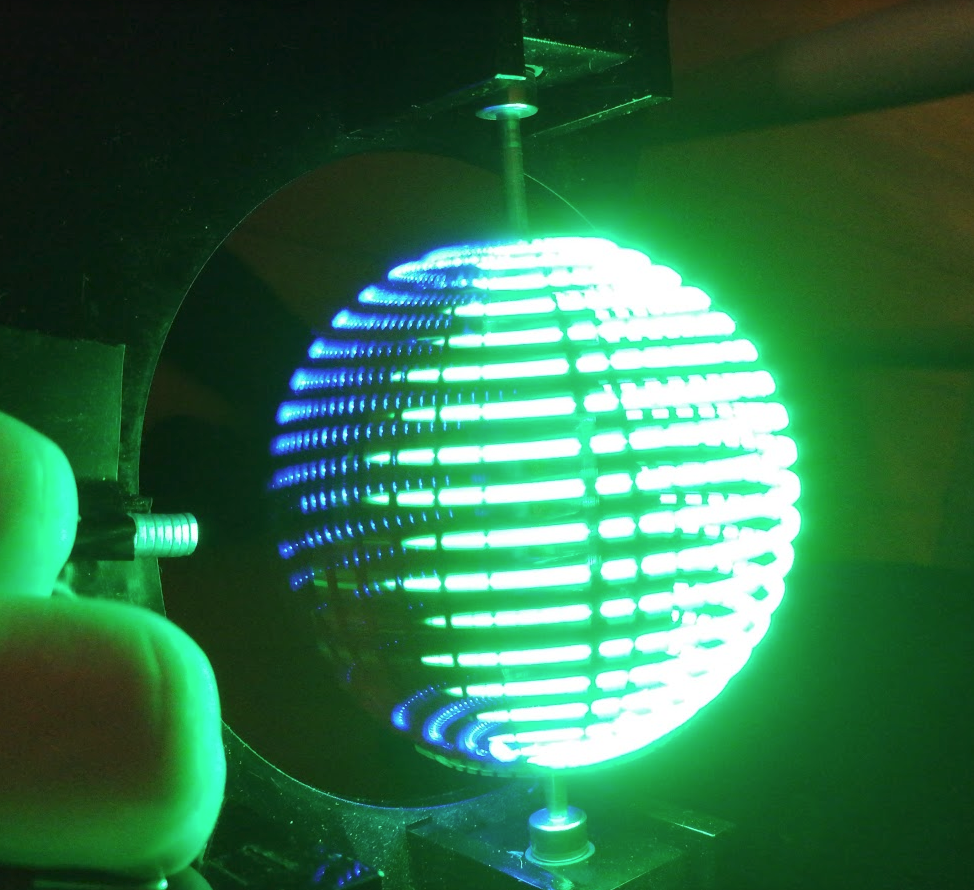
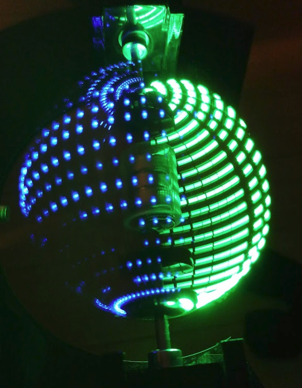
Here's some more eye candy:


These are showing an issue that I expected to come up, namely that all of the LEDs are mounting on one side of the PCB, albeit mounted sideways. You can pretty clearly see the effect of the blue and green being on the left and right side of the PCB, respectively, and then being covered up as it spins around.
For now, a diffuser is probably in order.
 Jarrett
Discussions
Become a Hackaday.io Member
Create an account to leave a comment. Already have an account? Log In.
That thing looks awesome!
So I understand there may be an issue with the driver PWM not being fast enough to light the LEDs visually continuously - or something like that - so I get that there are blue dots. But, then why are some areas of the green solid?
Are you sure? yes | no
It totally is still-to-be-investigated, because it's a bunch of work to get set up with the scope, so I've been putting it off.
The blue/green dots/dashes are plainly visible in person, too. When the thing spins slower, they become more elongated, and the dashes become more dot-like as the globe spins faster.
I don't _think_ there's a significant difference between the blue or green LEDs in that regard, I think the difference you're seeing in the pictures is more to do with the relative efficiencies, and therefore brightness of the LEDs. The green LEDs are set to about half the current limit as the blue, but because the green process is way way more efficient, they're still a lot brighter. I'll have to tweak that down a little.
So, could be wrong on that, but I think it's because of ghosting on the camera. That answer may change in the future :)
Are you sure? yes | no
That seems to me to be more of a mark/space problem, not overall speed. I dont know how the PWM is coded offhand, but the servo driver staggers switching and channel timing is offset rather than parallel synchronous. It doesnt matter in servos, the lag is imperceptible but here its critical. Perhaps its to do with this? ;-)
Are you sure? yes | no