-
How do they even work?
11/20/2018 at 17:38 • 0 commentsLet's talk about magnets. Specifically, I don't think I've mentioned here how the period of rotation is being triggered.
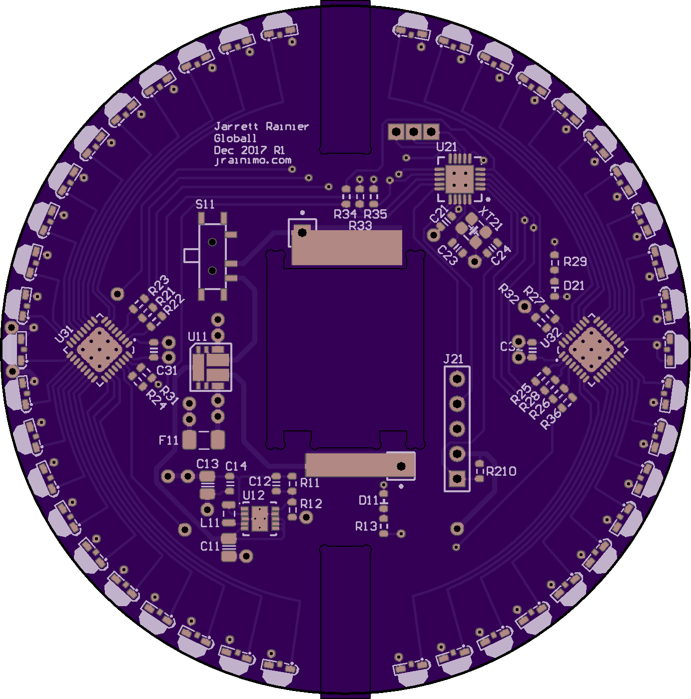
Here's the first log where I showed off the (first revision) PCB design:
https://hackaday.io/project/27580/log/74559-holding-and-shipping
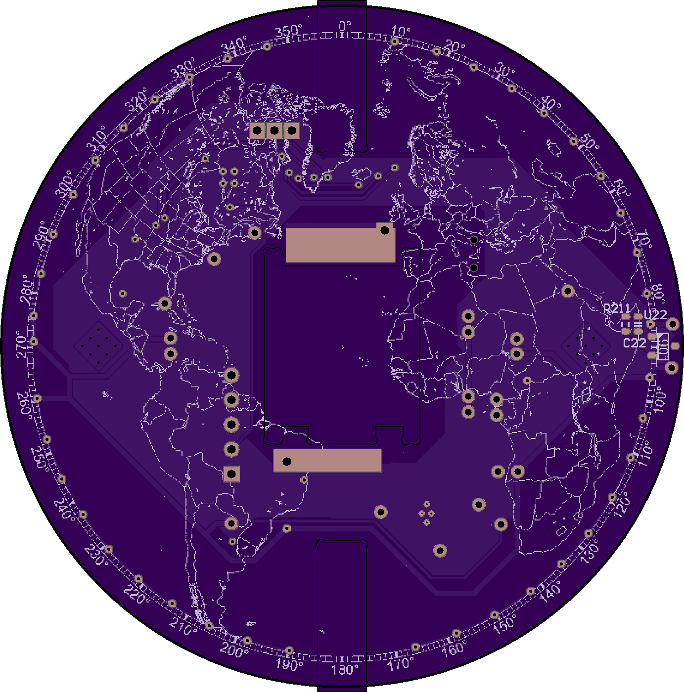
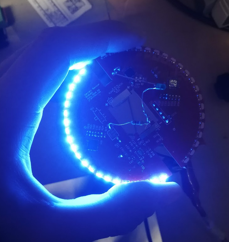
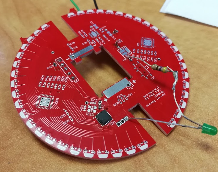
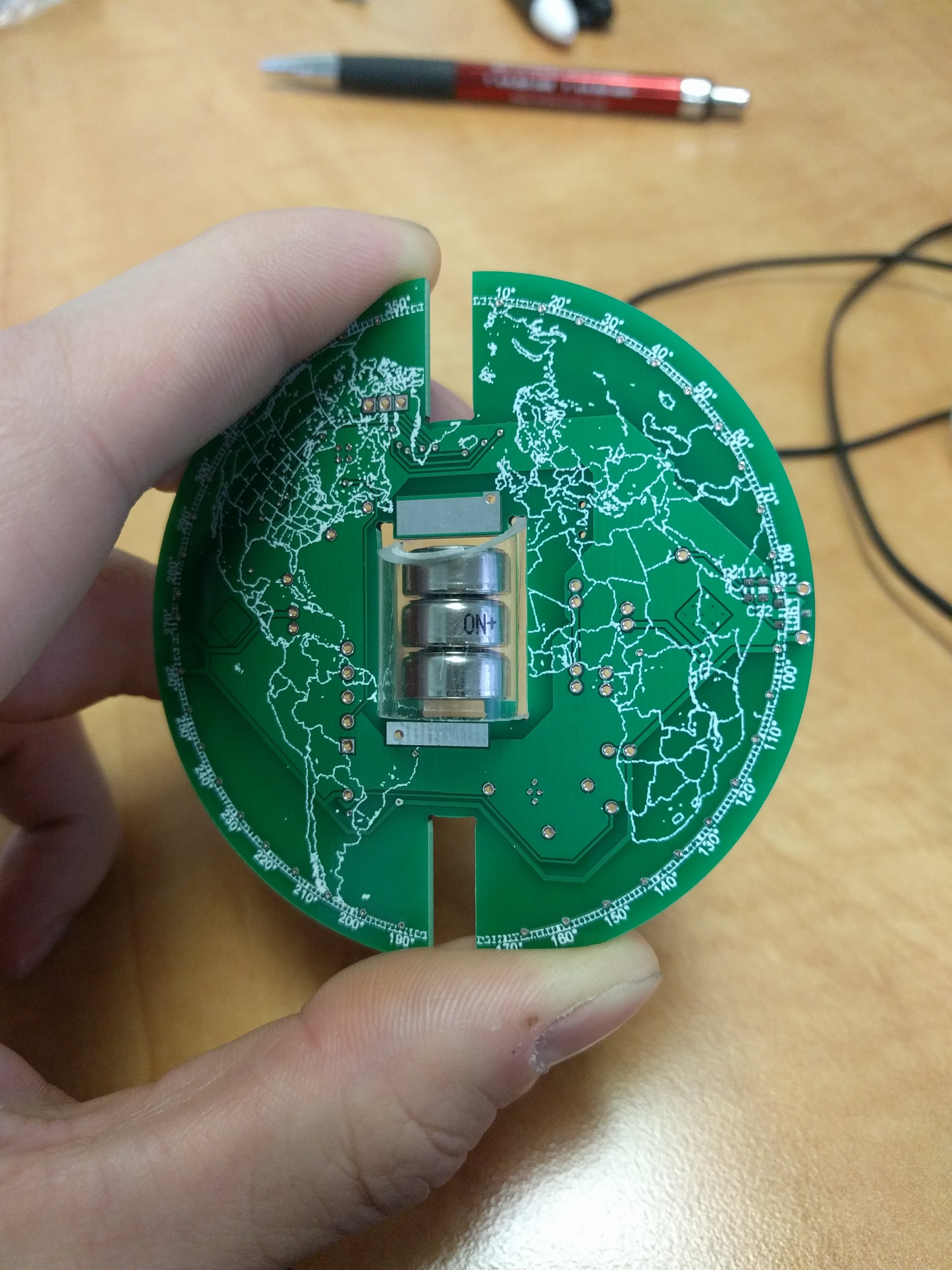
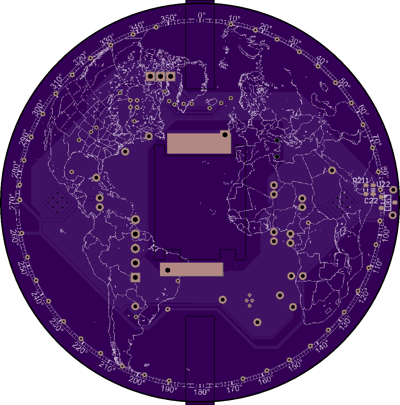
On the bottom of the PCB, you can see a footprint on the right side:
![]()
U22 is a Hall Effect sensor. The idea is that there is a magnet attached to the (stationary) frame, so it can trigger ever time that PCB edge spins past.
There are two issues with that, in general:
- Hall effect sensors are extremely slow. Most of the ones I checked out were in the order of 100ms to trigger and reset, and 10 Hz just isn't good enough!
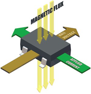
- All of the SMD packages sense magnetic fields perpendicular to the device, like so:
![]()
The first issued was solved by combing datasheets until I found something fast enough, and I did, the APS12205. The second issue was "solved" with a good bit of luck, as well as an additional problem that cropped up with this sensor.
As I hinted, it was actually quite difficult to find something that met my speed requirements, they're not common. But one of the downsides with this sensor, is that it is latching. That is, if you show it a north pole, it will hold its output high, even after you've taken it away. You need to show it a south pole to turn it off.
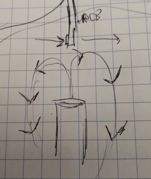
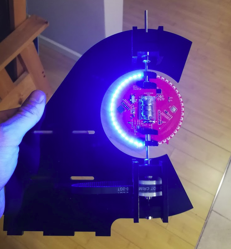
Solution:Taking a top view of the entire system, with the PCB rotating counter-clockwise:
Assuming the sensor is sensitive enough, and the magnet is strong enough, the sensor passes through two opposing magnetic fields throughout its rotation. It works! Potentially problem, avoided through good fortune.
While writing this log, I stumbled across an article (from 2003!) talking about a Hall Effect sensor with something that called an "integrated magnetic concentrator". Note to self, look into this for a project of some sort, it looks rad.
-
The PCB Goes In
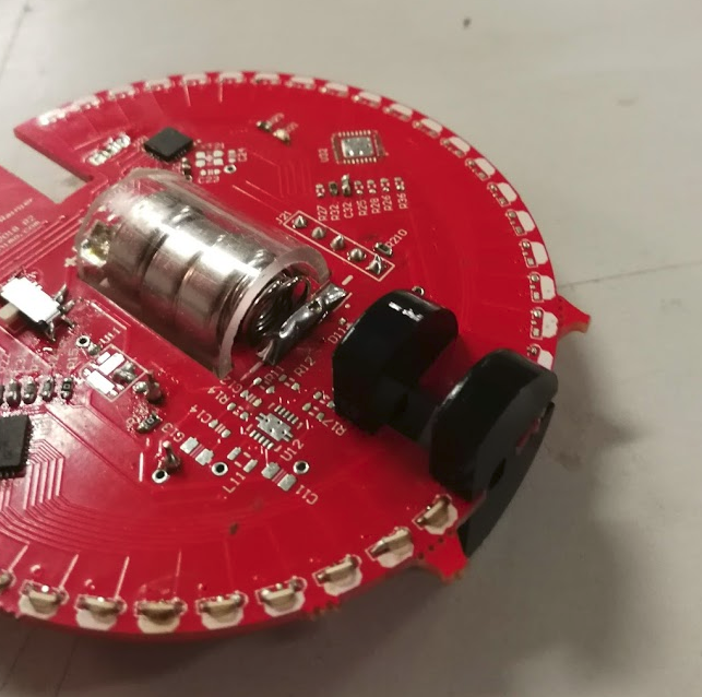
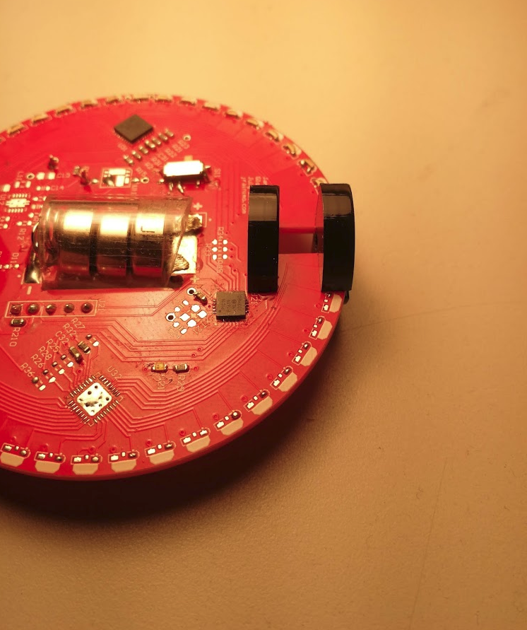
11/18/2018 at 02:46 • 0 commentsOh yes. Exciting.
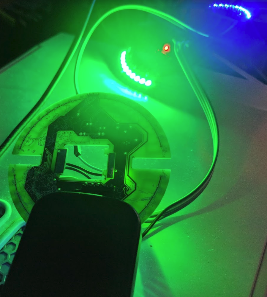
Notice that the batteries work fine, too! I was genuinely worried that they wouldn't be able to handle the current.
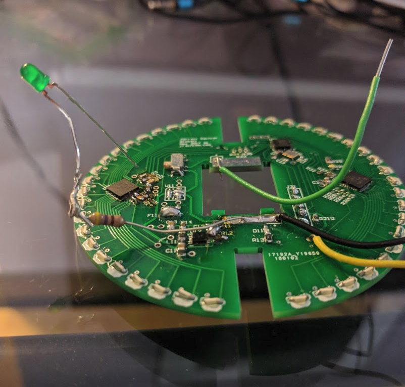
Only one side, the blue side (also the Best side) has been assembled on the PCB. There's going to be one more revision for sure, so this is totally fine for testing without putting more work in than necessary.
Here is the last log (from almost a year ago!) that shows the mechanical design. Nothing has changed on that front, and I haven't implemented the changes I discussed.
Those black acrylic pieces that couple the PCB to the shafts needed to be laser cut again, because of the slight difference in thickness between the acrylic mock-up and the real PCB.
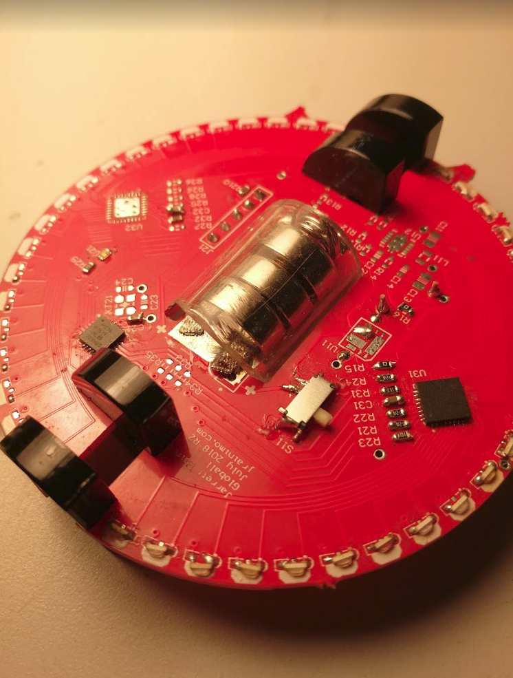
So I did that, and there was a problem that I kinda foresaw, but decided to cross it when I got to it. When the circles are full length, they can't make it past those surfacemount LEDs. This time, I just sliced off a corner, but that might not be a great idea when I have LEDs on both sides. It'll be a very weak coupler. Maybe metal or even wood might be viable, anything is stronger than acrylic. Alternatively, I could add a circular cutout in the next PCB to allow inserting the couplers sideways, then rotating in situ.
Either way, this works, just barely.
The microcontroller is mounted suuuuper close to where the coupler has to come across. I don't remember if I intentionally considered that in my design when I originally did the PCB, but it still makes me uncomfortable! Also, the spare GPIO are covered up, although my initial debugging stage is done, probably.
You can see where I soldered some copper braid around the edge of the PCB for battery contacts. I'm actually not too unhappy with that. On the other side, I soldered a spring intended for battery holders. The force on the spring is too high at the moment, though. While trying to load batteries into the holder for the first time, I let go and one of them shot across the building at (pretty sure) mach 1, never to be found again.
-
Good Enough For Testing
11/09/2018 at 21:47 • 2 commentsWith an entire side done, I can move on from the electronic side for now. With the microcontroller, LED drivers, and all of the LEDs soldered on there, I can work on code and fit it into the mechanical test fixture.
For some interesting stats:
All 20 blue LEDs full-on is currently drawing almost exactly 70mA at 3.0V. The current setting resistor for the TLC5947 is 1.3kOhm.
Also in keeping with the bodgery-theme, I managed to salvage the microcontroller, driver, and most of the LEDs from the old board. I did have to replace 4 LEDs because they did not survive the transplant. I replaced all of the passives, though, those were toasty.
Code for the PIC is coming along nicely - I think I have a proof of concept that should work almost perfectly. I can't test it until it's in the assembly and spinning, however, so that is next.
The LR44 batteries I intend to use are rated at about 50 ohms at 1.42V, which works out to about 28mA, regardless of how many I stack up in series. That means that I suspect I will probably have to reduce the current limit on the LED driver, or just set it down in software. Hard to say, it's also possible the battery will be able to handle the quick discharge spikes every once in a while.
-
PCB R2
10/25/2018 at 22:56 • 0 commentsNew PCBs arrived a month or two back. I just haven't had time to do anything with them before now!
In the Laziest Re-Bodge Ever, I used a hot air gun to take off the PIC and some other stuff from the old board, and dropped it onto the new board.
Haven't plugged it in yet, but fingers crossed I haven't (literally) fried the microcontroller!
-
Oh yeah, I'm definitely going to have to respin
06/30/2018 at 22:48 • 0 commentsBack in February, I quickly soldered some components onto my board, and it didn't seem to work, and I suddenly got slammed with Actual Work That Matters, so I didn't investigate much further.
Recently, I finally got some spare time to do some digging.
I should mention, I designed this PCB in, like, November or something, so I don't remember the actual act of *designing it*, and this is just as much of a journey for me as it will be for you!
Skeeeetchy
There are three main sections of note:
- The power supply (currently bypassed) - we'll come back to this.
- The microcontroller, working!
- The LED control section.
The LED section, using the TLC5947, just doesn't turn on or respond to communication.
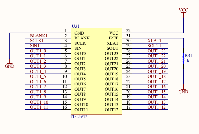
After probing around a little, I went back to the datasheet, and compared to my designs:
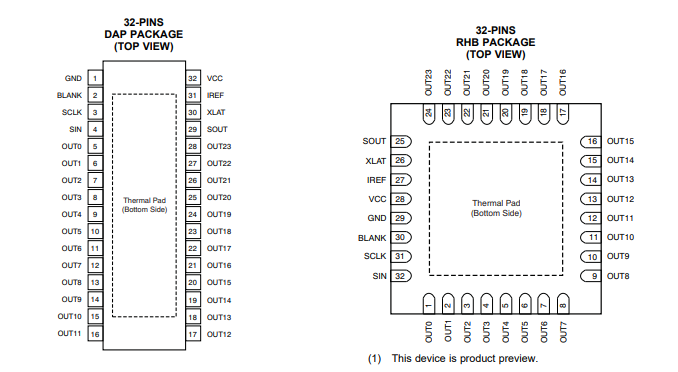
Hmmm, I'm already seeing something to watch out for. The pin numbers in the different packages are different.
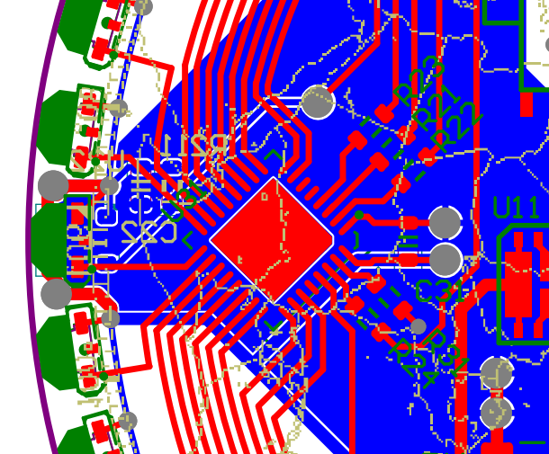
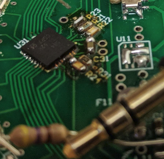
My PCB:
That's not good. The big red square in the centre of the image is U31, the LED driver IC. Just to the right of that, you can see C31, a bypass cap. These usually connect VCC to GND, and on this PCB, it is straddling pin 1 and pin 32.
Yeah, that's how I hooked it up to my schematic. That's not good! As you can see from the datasheet screencap, those are not the proper VCC or GND pins, and everything else is shifted, too. Bodging this to work is tricky, too - The correct VCC pin is 28, that stub in the bottom right of my PCB.
It's tiiiiiny. One of those pins just to the left of R24.
Shown here with a 3.5mm audio jack for scale, and the twice-reflowed burnt resistors.
I'm not sure just yet if I should continue bodging with a breakout board, or fix and send it off for manufacturing again. Leaning towards the latter, but if I had free time, I could totally lift off the chip, solder it onto a breakout board, and then solder point to point to the QFN pads.
Just to double check my microcontroller section, I wired up the external LED driver breakout board I have to some test points:
Works! Microcontroller portion is good.
-
PCB Day Best Day
02/08/2018 at 16:29 • 0 comments![]()
Have not finished populating the board or doing any tests yet. The board looks good, though! Final soldermask colour will probably be black, but this particular boardhouse wanted extra for that, and I expect to have to respin this, so I want the cheapest price possible.
-
Holding and Shipping
01/11/2018 at 19:14 • 0 commentsLack of updates hasn't meant lack of progress here. Since I last wrote, two things have happened:
I've built a mock-up for one potential solution to my battery holder problem.
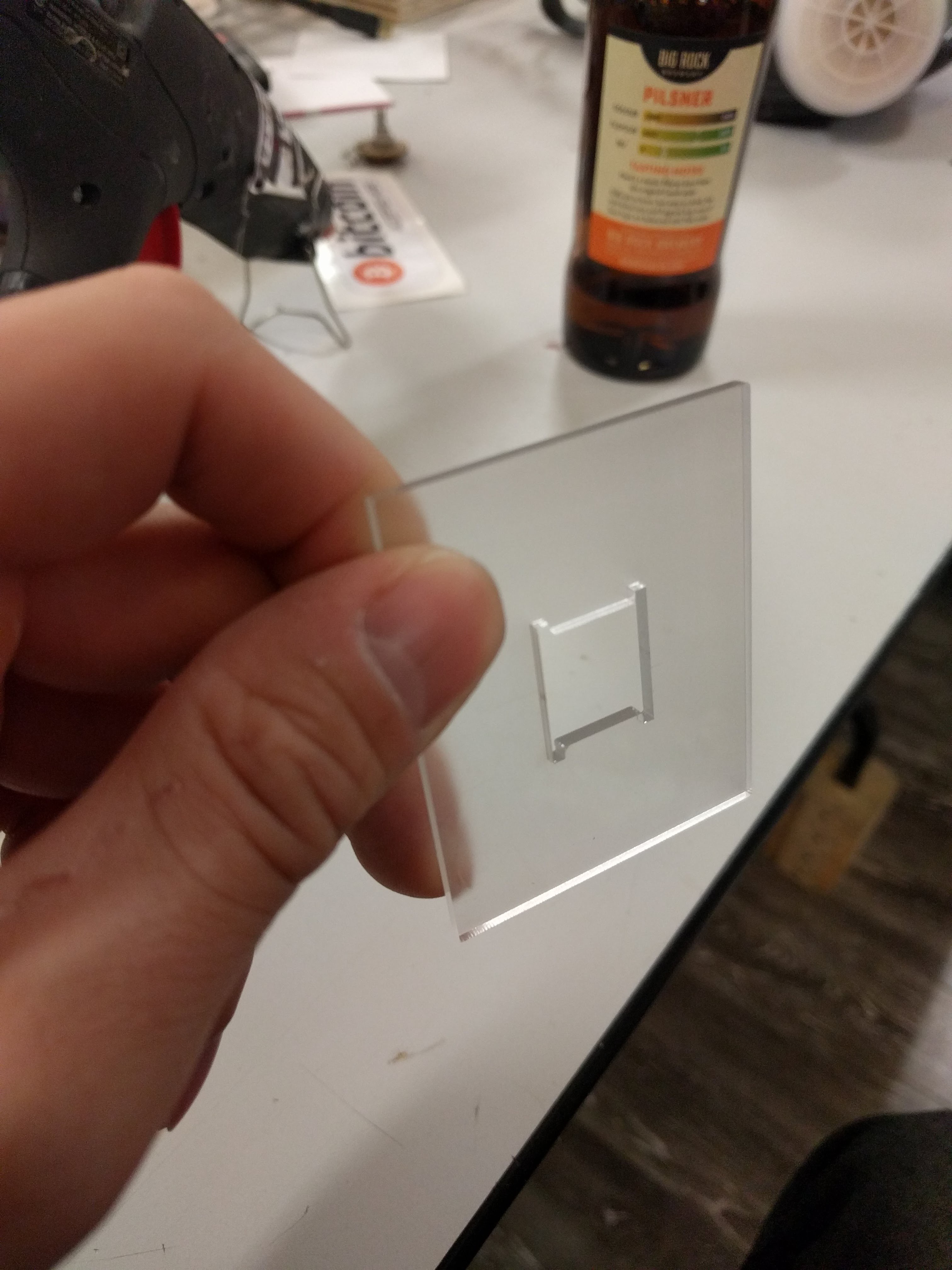
First, I laser-cut a shape into some acrylic:
![]()
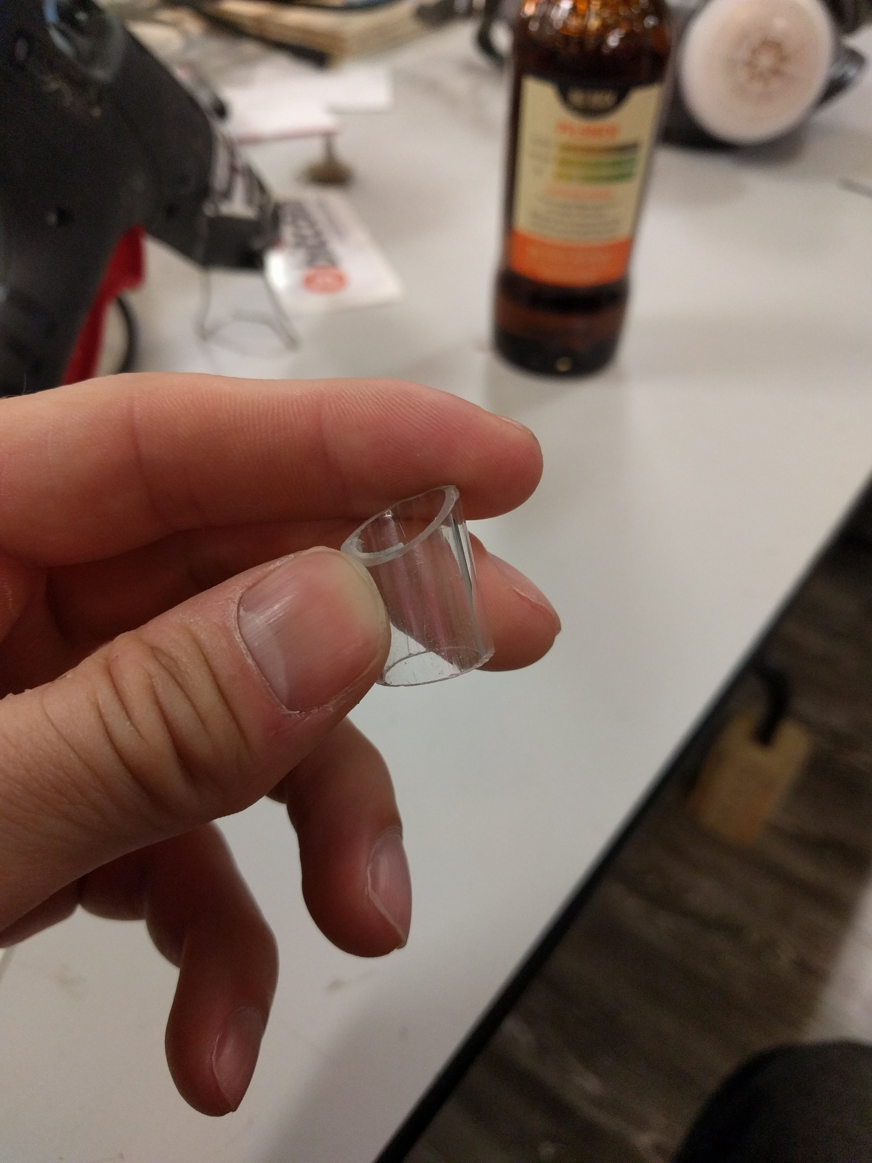
Then, I cut and sanded an angle into an acrylic tube:
![]()
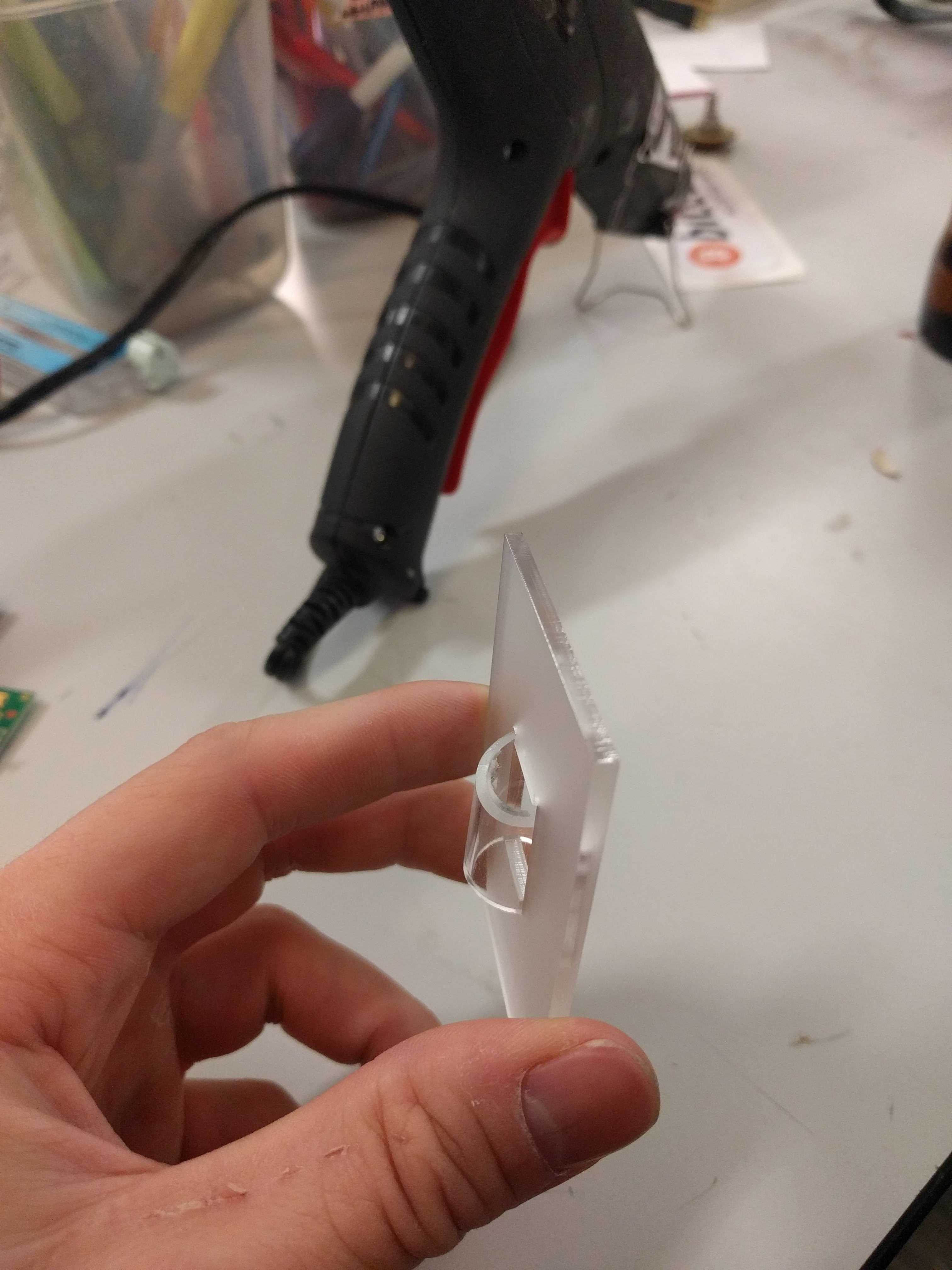
It seems to slide onto the cutout pretty easily, and then rotating the tube so that the long end is wedged into the side cuts, and locks into place.
![]()
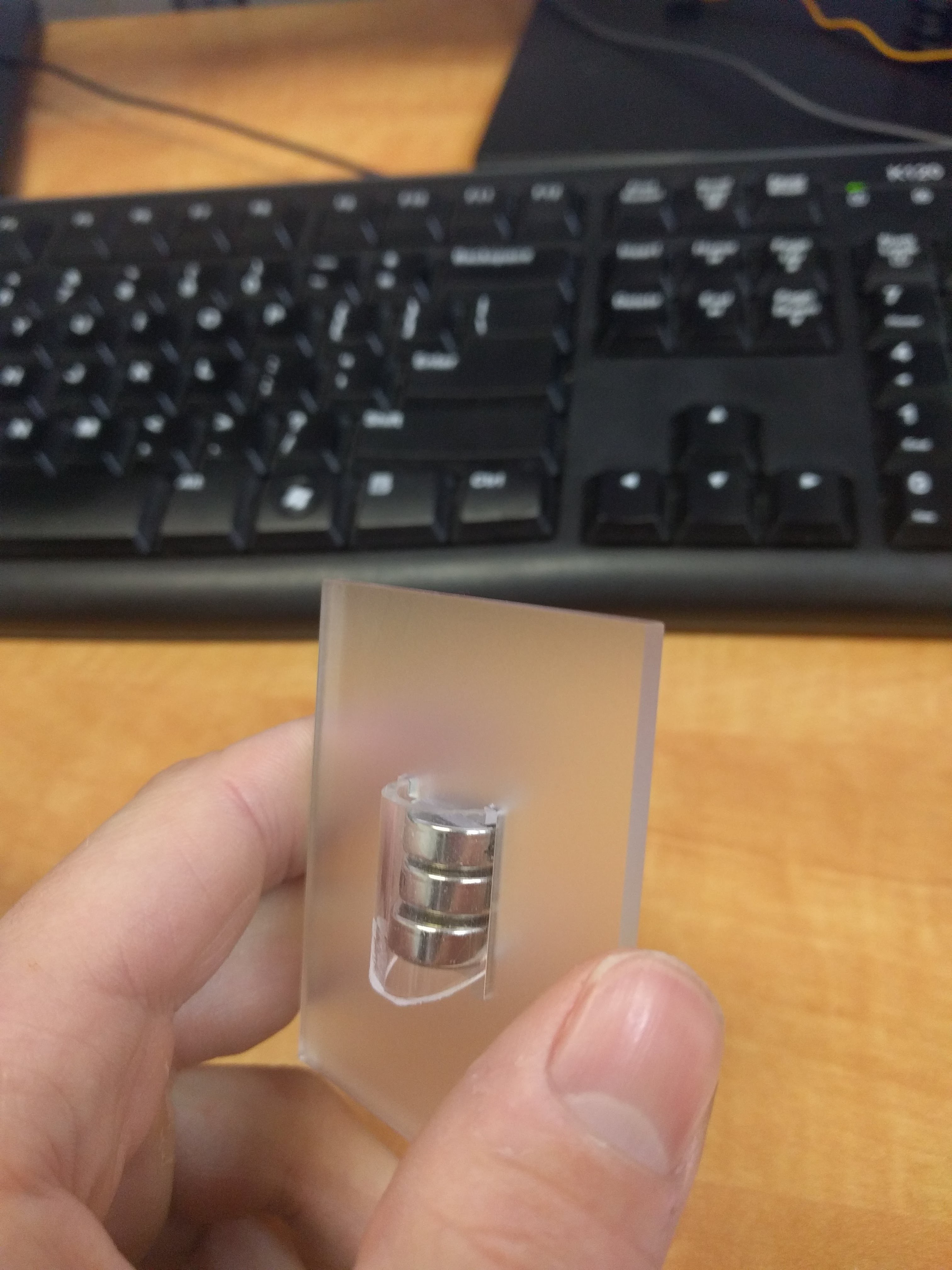
It seems to work decently well. The tube has an inner diametre of 12mm, just over the LR44 battery's 11.7mm, so they fit with only a little bit of rattle.
![]()
The other thing I've done is sent off a PCB for manufacturing. Not actually OSHPark, unfortunately, so I don't expect to see it until the end of the month at the earliest.
![]()
![]()
-
Measured frequency
12/29/2017 at 19:58 • 3 commentsRevisiting this project log, I had some ballpark guesstimates on timing, and it wasn't looking as good as I'd hoped. So I attacked the problem again, this time in the lab.
First of all, I simplified the main loop of code to this:
            LATAbits.LATA5 = 1;
            for(i = 0; i < VPIXELS; i++) {
                setChannel(blob, i, blueMap[i]);
            }
            LEDMap(blob);
            LATAbits.LATA5 = 0;
            for(i = 0; i < 2; i++) {
                __delay_ms(10);
            }
That sets port A5 high while we're actually doing work and gives me something to trigger on.
Remember that setChannel is there to process data from storage into an array of the format that the driver chip takes, and LEDMap sends the data to the LED driver over SPI.
I'm expecting setChannel to take a long time, and LEDMap to be fairly quick, given that SPI is done in hardware at clockspeed/4.
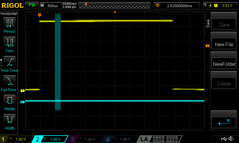
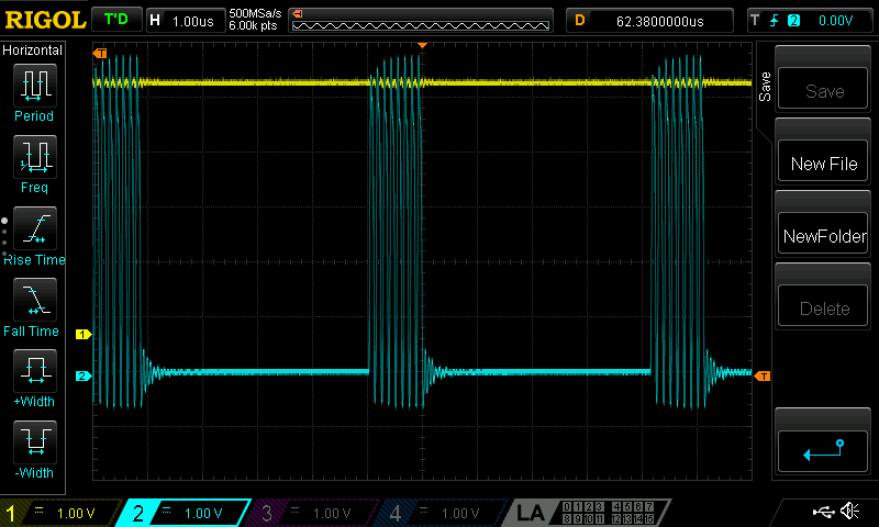
Here's what the whole loop looks like (yellow is PA5, blue is SDO/ SPI data):
![]()
That doesn't look right! Why is SDO all the way to the left?
We go to LEDMap, where that data is sent:
void LEDMap(uint8_t *blob)
{
    uint8_t data = 0;

    XLAT = 0;

    for(int i = TABLESIZE - 1; i >= 0; i--) {
        data = *(blob + i);
        SPIWrite(data);
    }

    XLAT = 1;
    __delay_ms(10);
    XLAT = 0;
}
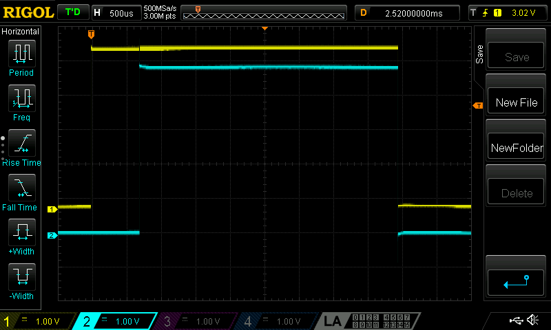
Oh yeah, that makes sense. __delay_ms(10) is a little excessive. I meant to tune that down as far as the driver would allow, but it slipped my mind completely.
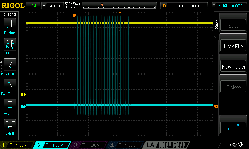
Putting the scope on XLAT proves that nicely:
![]()
So two things come out of this that are very interesting. The more important takeaway is that, if the XLAT timing is reduced to almost nothing, each loop of main() should take around 750us.
The other is that a 10ms delay is nowhere near 10ms. Close to 40ms, in fact. Why is that?
The clue comes from the poor Microchip documentation for built in functions. Historically, before their (pretty excellent) redo of their framework, there was an important constant called _XTAL_FREQ.
Some built-in functions, such as the delay functions, required it to know what speed the crystal was running at, and generate accurate(ish) timings.
With the framework redesign, as far as I can tell, those delay functions are still the recommended method. You need to specify _XTAL_FREQ yourself, however.
In my system.h file, I have written:#define SYS_FREQ 12000000L #define FCY SYS_FREQ/4 #define _XTAL_FREQ SYS_FREQHmmm. So, future note: _XTAL_FREQ must equal FCY, not SYS_FREQ.
Okay, back to the task at hand. Or at least, some fun facts,
![]()
Each byte is taking around 5us to send.
![]()
The whole block to load up the LED driver with data is about 200us to send.
Okay, so at a 750us period, I can refresh one LED driver 1333 times per second. The final board has two drivers, so I'm looking at 666Hz.
Ideally, as the globe spins, I'd have a horizontal resolution that is equal to my vertical resolution. I have 20 LEDs going up each edge, so multiply that by Pi, and I require 63-ish refreshes required for each revolution of the disc.
Treating it like a movie screen, that's a little over 10FPS at each physical point on the globe. That's not really enough for animation, but for a static light/dark image, I think it's right on the edge of being okay.
I'm not certain I can get my motor spinning that slowly, however.
But there are two optimisations that can still be done. Currently testing one out, and I think it'll be pretty fantastic if it pans out.
-
Mechanicals are firming up
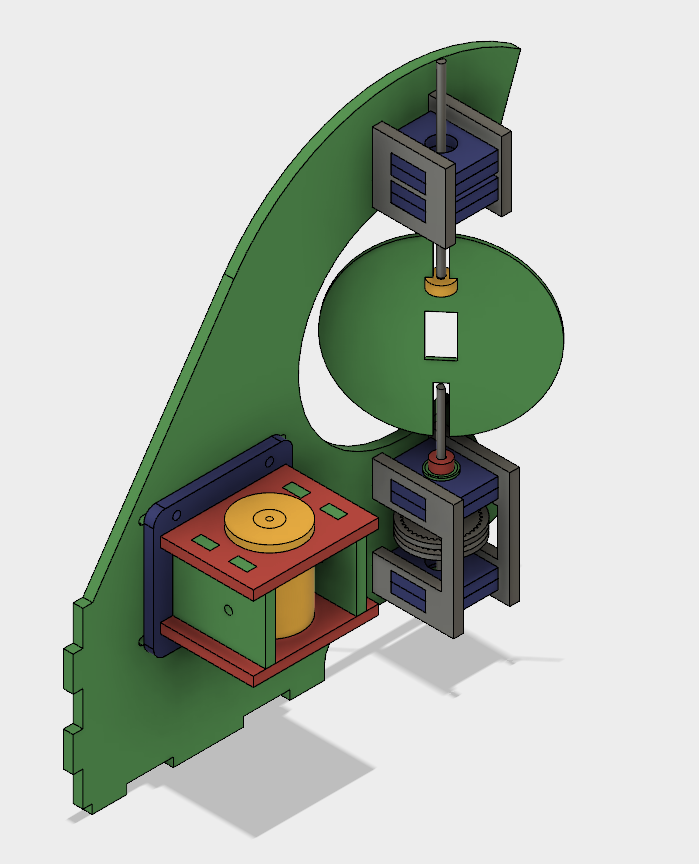
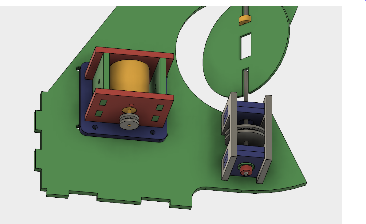
12/18/2017 at 03:07 • 0 commentsAs mentioned earlier, some minor mechanical redesign was in order.
The driven pulley was moved to prevent cantilevering, and I switched to D-profile shaft to allow some extra laser-cut pieces to couple the PCB.
Cut it all out and assembly time.
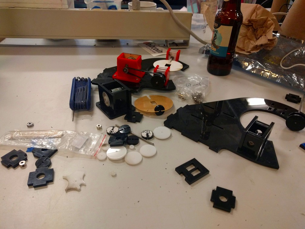
![]()
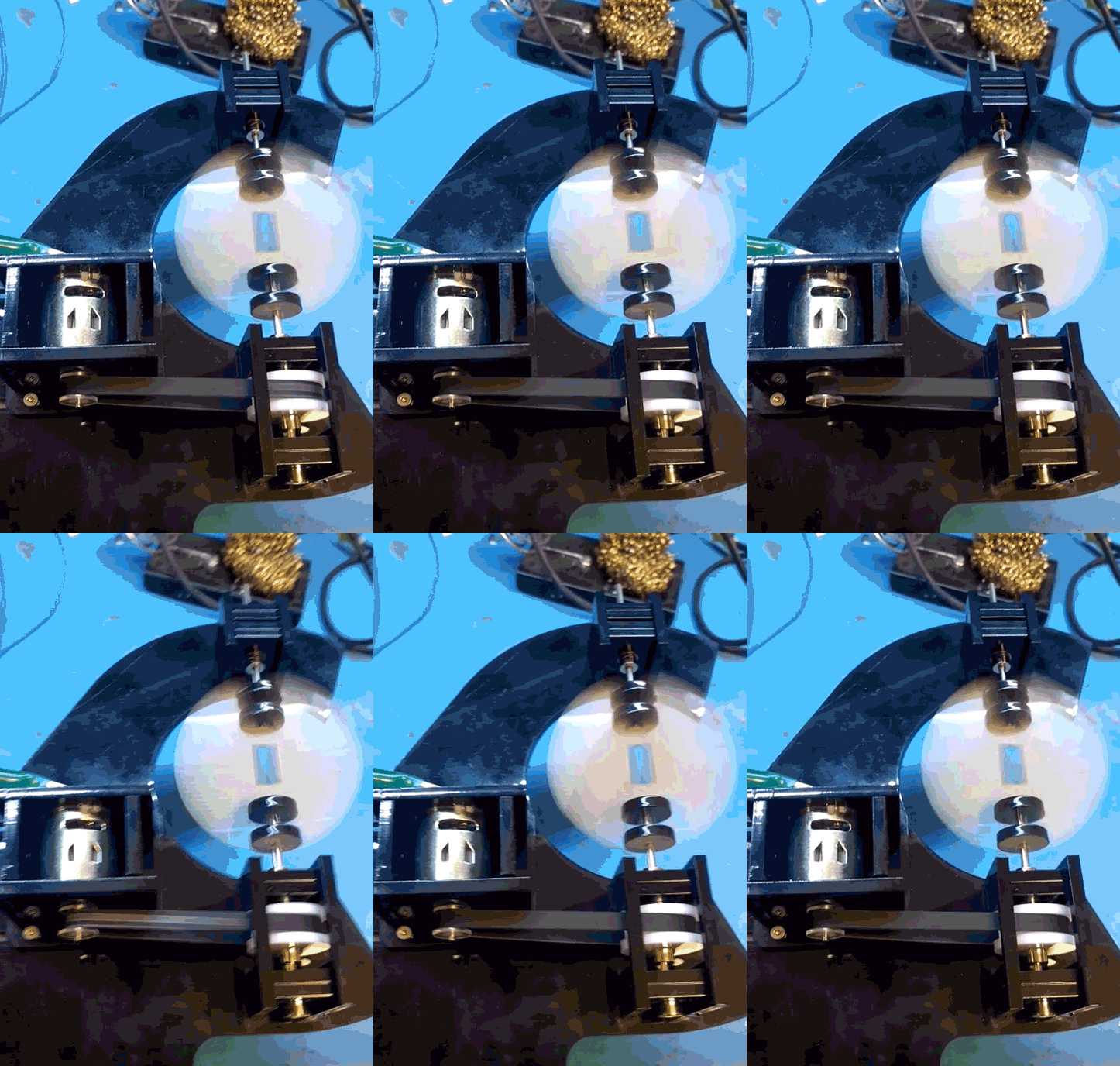
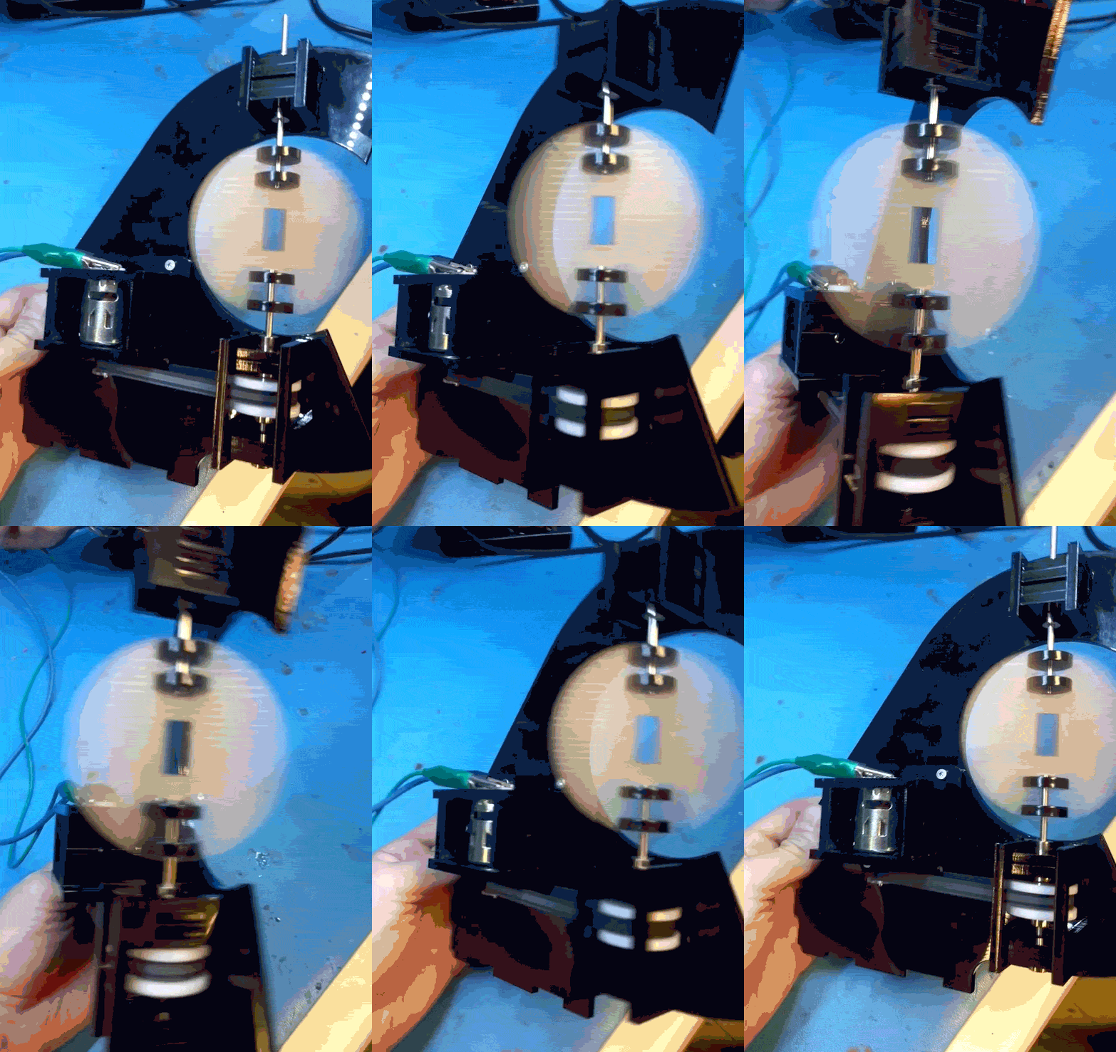
Resulting in massive lossy GIFs:
![]()
I'm actually super stoked about the speed and how stable the whole thing is. Excuse the handheld shaky-cam.
![]()
A couple minor issues:
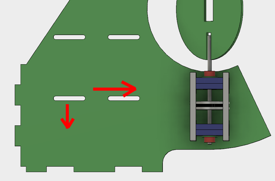
The large pulley is still a little bit close to the upper bearing, it's either rubbing or in danger of rubbing. There's a ton of room below it, so what needs to be changed are the motor mounting slots. A little bit lower. Additionally, the belt is at full tension while the motor carriage all the way to the right. So it works, but it would be nice to have a little bit more clearance.
So, in summary:
Down 3mm, to the right 3mm.
-
A brief note on peripherals, speed, and memory
12/04/2017 at 20:31 • 0 commentsLet's dive into how the code works, presently.
The main loop looks like this:
    while(1)
    {

        if (frame != angleInt && angleInt < HPIXELS) {
            frame = angleInt;

            DisableInterrupts();
            for(i = 0; i < VPIXELS; i++) {
                setChannel(blob, i, blueMap[frame][i]);
                setChannel(blob, 23 - i, greenMap[frame][i]);
            }
            LEDMap(blob);
            EnableInterrupts();

        }
    }
This is a little different than the final design, but the principle is similar. The testbench has one LED driver running two banks of 10 LEDs each. The final design will use 20 LEDs driven by two ICs. That should mean the main difference is that two LEDMap calls will be made.
Currently, the channel assignment code looks like this:
void setChannel(uint8_t *blob, uint8_t channel, uint16_t value) {
    uint8_t lvalue;
    uint8_t rvalue;
    uint8_t newVal;
    uint8_t byteAddr;

    if(channel % 2 == 0) {
        byteAddr = (channel * 3) >> 1;
        lvalue = (uint8_t)(value & 0xFF);
        rvalue = (uint8_t)(value >> 8);

        *(blob + byteAddr) = lvalue;
        newVal = (*(blob + byteAddr + 1)) & 0xF0;
        newVal = rvalue | newVal;

        *(blob + byteAddr + 1) = newVal;
    } else {
        byteAddr = (((channel - 1) * 3) >> 1) + 1;

        lvalue = (uint8_t)(value << 4) & 0xF0;
        rvalue = (uint8_t)(value >> 4);

        newVal = (*(blob + byteAddr)) & 0x0F;
        newVal = lvalue | newVal;

        *(blob + byteAddr) = newVal;
        *(blob + byteAddr + 1) = rvalue;
    }
}

void LEDMap(uint8_t *blob)
{
    uint8_t data = 0;

    XLAT = 0;

    for(int i = TABLESIZE - 1; i >= 0; i--) {
        data = *(blob + i);
        SPIWrite(data);
    }

    XLAT = 1;
    __delay_ms(10);
    XLAT = 0;
}
setChannel takes in a 16-bit value and address and puts it into a table of 12-bit values, using some magic that offsets everything into the proper address. The LED driver uses 12-bits for each channel, sent sequentially. There's a pretty glaring huge problem with this: It takes a ton of time to go through each row, many times per rotation. It has to be run for each pixel. In my final board, that will be 20 LEDs per driver, two drivers, and I'm hoping to get at least the same resolution on the vertical as horizontal (so 20 * Pi ~= 63 LED changes per rotation).
With a very rough test using AVR GCC with the Godbolt compiler (I know it's not the right architecture), we get:
~80 instructions * 24 channels * 2 banks = 3840 instructions for setChannel
~20 instructions * 36 channels * 2 banks = 1440 instructions for LEDMap
The PIC internal clock is 32MHz, but the instruction clock divides that by four:
8E6 / (3840 + 1440 instructions) = 1515 Hz for the entire loop.
Divide that again by 63 virtual horizontal pixels, and you get the full rotation of the PCB being maximum about 24 RPM. That's not nearly good enough!
The bulk of the processor time here is taken up by copying the currently active frame from input storage data into the output array, aligning it properly into 12-bit channels. What that means is that I can stick using 8-bit data and get more data out of my storage, at the cost of brightness resolution. We've discovered that it's also at the cost of unacceptable processor time, so I'll give the other method a shot, and try storing everything as a 36-byte table, representing 24 12-bit channels.
That brings us into a topic I've skipped talking about so far. The PIC family of microcontrollers is interesting because it is absolutely huge, with all kinds of different peripherals and weird combinations.
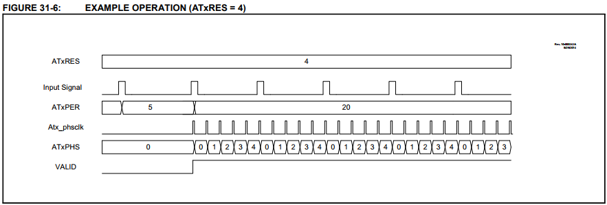
The one I've been using for testing, and likely the same (or similar) one I'll be using in the final model is the PIC16F1619. It is one of only 4 different models that have a poorly marketed and even more poorly documented Angular Timer. It's a fantastic peripheral, though, that does exactly what I need. You give it a periodic signal (eg. Hall Effect sensor triggered by a magnet), and it will divide that time up spit out an interrupt at regular intervals, depending on how many interrupts you want per period.
So that's taken a load off my code. After I set it up, the hardware just handles that portion for free.
Something that would be really nice, but probably isn't going to happen would be DMA. DMA peripherals are conspicuously absent from most of the 8-bit lines of Microchip's part selectors.
A little more digging however, turns up evidence that there is an SPI DMA peripheral in some of the newer PIC18FxxJxx families. As far as I can tell, it only mentioned in the datasheets of the affected products. Great marketing, Microchip!
None of those have the angular timer, however. I may do an analysis of the relative benefits of each peripheral at some point in the future, but for now, I'll stick with the PIC16F1619.
 Jarrett