 deʃhipu
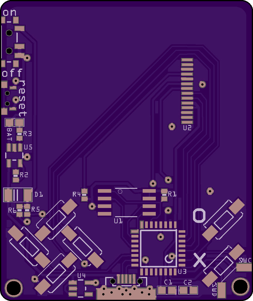
After writing down all the changes I wanted, I started to play with the PCB to see if they were possible, and of course I made another version with all the changes I wanted:
And the back:
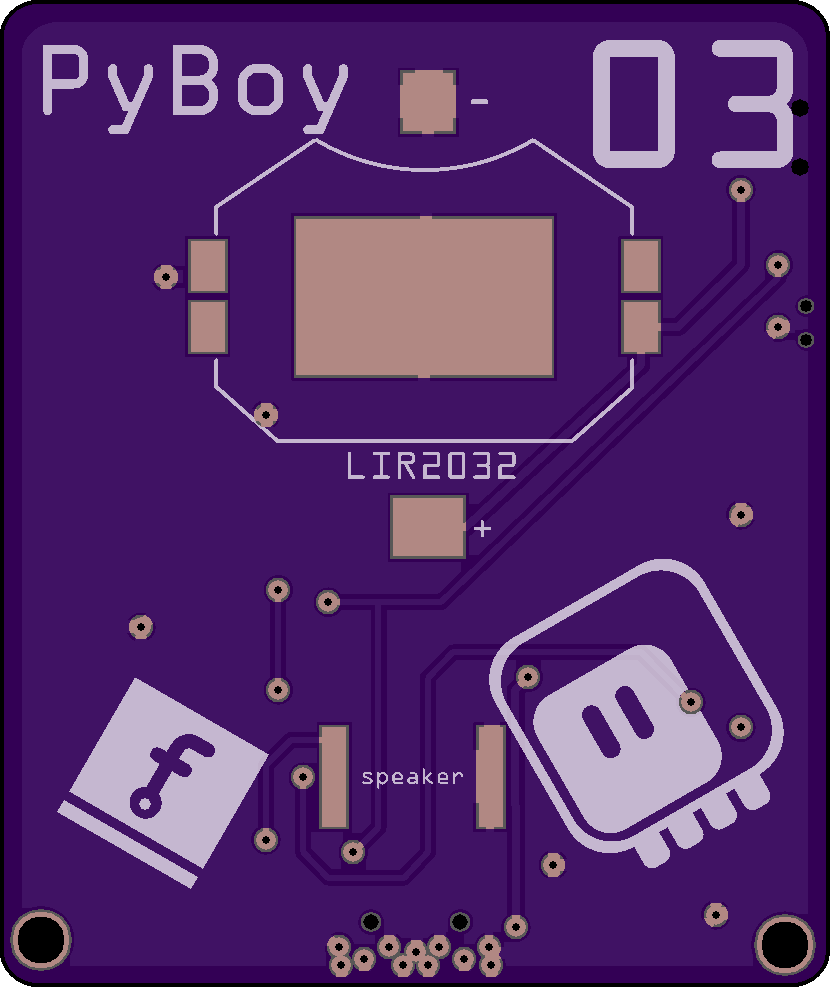
I managed to keep the back clear of parts, save for the battery and speaker, which really can't fit anywhere else. I also modified the battery charging circuit a little, to make it possible to charge the battery with the unit powered off. Hopefully it won't drain the battery.
I'm going to sit on this a little bit and if I don't have any more ideas, I will order it tomorrow.
Discussions
Become a Hackaday.io Member
Create an account to leave a comment. Already have an account? Log In.
The via by the on/off switch will suck solder away from the pad it's connected to. Same with the one by U4. If you're planning on using reflow for this, you should probably move those so there's soldermask between the pads and vias, or just tent the vias.
Are you sure? yes | no
Thanks, I will think about what to do with them. Then again, I've heard about this problem before, and somehow it never happened to me when using the hot air gun and solder paste. Perhaps it's because I use way too much solder paste on the pads anyways. But it would be nice to have the option to mass-produce those at some point.
Are you sure? yes | no