Close
0%
0%

Open-Source 6-Axis Robotic Arm

A completely-open, scratch-built PUMA arm with 24" reach and 1lb payload

Similar projects worth following
The goal of this project is to create a reference design for a 6-axis PUMA-type arm and parallel gripper with a payload of about 16oz/.5kg and a reach of 24"/60cm and a parts cost of under $1500. While a robot this size won't enable world domination, it's enough to do real work: flip a burger guided by computer vision, pick dirty laundry up off the floor, unload parts from a 3D printer, or grab you a tasty beverage out of a cooler.

Every part of the stack from hardware to software will use open design, open software, and parts designed to be easy to make and maximize use of commodity parts.

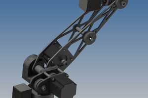
In some ways, this arm is pretty simple: it's just a bunch of joints driven by stepper motors. The basic design directly follows the PUMA architecture, and everything follows from there. There's just a lot of slow design work figuring out how to squeeze everything together, work out motor torque requirements, gear spacing, and eventually, wire routing. I was surprised when I didn't find any well-documented (and finished) builds of things like this, so I decided I'd take a crack at the dirty work of wringing all of this out and putting out a plan for others to replicate my work.

The real tricky stuff comes in controlling the arm. I've used LinuxCNC for about six years on a variety of progressively-larger machines up to the Tormach PCNC 1100 I have today, and it's been successfully used to drive a variety of non-Cartesian kinematic mechanisms. In theory, it only needs some relevant configuration (namely, the Denavik-Hartenberg Parameters) and it can solve the inverse kinematics problems so that the user can order the arm from position A to position B in "world coordinates" and LinuxCNC works out the joint positions and moves the arm. That's the goal at least.

Then there's the gripper. If I knew what I was doing, I'd have known that gripper design is in fact a whole discipline within the robotics field, and that a gripper is really its own self-contained robot. I settled on a parallel gripper as the starting point, since it can pick up and put down a wide range of objects, but in principle any end-effector of appropriate size should be workable.

Mostly, the goal for this iteration is just to get everything minimally working, and then start identifying weak points and areas for further refinement.

  • Do you even lift, bro? (yes!)

    Colin Kingsbury12/05/2016 at 03:53 0 comments

    This is a long time coming. A lot of life happened in the past year to slow down progress on this project, but it never stopped it. Almost three years ago, I set a goal to be able to pick something up and put it down, and this weekend I've been able to do that, repeatably. There's a lot more to do, still, but we can now say the basic idea is possible.


  • A lot of progress, a little documentation

    Colin Kingsbury11/04/2016 at 03:39 0 comments

    While I haven't updated this project or my mine website in over a year, that's mainly because I've spent most of my free time focused on building and testing and iterating, rather than documenting my progress. The truth is the past year was a pretty rough one for me, as I lost someone very close to me, and then a month later got the lease on my shop yanked out from under me, forcing me to focus on relocating rather than building for a few months.

    But all things pass, and by late spring I was settled in again (I was fortunately able to find a second affordable small industrial space in Boston, which required a lot of luck) and since then I've worked through a couple iterations of the control electronics, which are not done but are improving, and the third or fourth version of the gripper, which looks like it might be the one that works. I have some video of that recorded and will be loading up to Youtube soon.

    At this point, I think I could have the arm capable of picking an object up as soon as this weekend, which will be a neat milestone considering that I began working on this project in its original form over three years ago. It's not yet ready for primetime--the electronics are still very messy and not well-integrated physically, and I'm still missing a few functions like homing. But it's getting there, and almost all the basic building blocks are working.

  • A Waist of Time

    Colin Kingsbury10/05/2015 at 17:28 1 comment

    Things are starting to move quickly now. I have the arm mounted to a proper base so the "waist" joint is moving. It's a small incremental step, but it allows for much larger motions that look cool on camera. I also spent some time cleaning up the cabling before I spend six hours chasing a bug due to a pinched wire or something.

    The next issue I want to solve is the synchronization of the joints. They're starting at the same time as designed, but they're supposed to adjust their speeds so that they arrive at the final position at the same time as well. That's not happening, which could be due to any number of issues in the firmware.

  • 4-Joint Integration Test

    Colin Kingsbury10/02/2015 at 03:48 0 comments

    Time for a big update!

    Progress slowed a bit during summer months but a lot of big changes were made. This video shows 4 joints running simultaneously in something a lot closer to a "production" configuration than ever before. There's still plenty of work to be done, but with this, I feel like the end is almost in sight.

    As for the changes, there were two big ones. First, I swapped the Arduino Uno-based joint controllers for Teensy 3.1s. The Unos were struggling to run step rates of over 6000/sec, and that just made for painfully slow joints. The Teensy can drive Accelstepper happily at far higher rates than needed, and provides capacity to spare to add more functionality. At $12 each for the LC version, it's also cheap.

    Second, I gave up on the Pololu 8825-based stepper drivers and switched to the Panucatt Devices version. It's based on the same TI chip, and fits the same basic footprint, but everything else about is is just far better, for only a few dollars more. It comes with a nice little heatsink, which may or may not be enough without forced cooling for the 1.8A motor that runs the "elbow" joint, but is plenty for the smaller wrist motors.

    More importantly, it's laid out so that you don't need the hands of a neurosurgeon to adjust the motor current. Both boards use the same basic idea of a little pot and a spot you probe to set a voltage which determines the motor current. On the Pololu board, the point is tiny and located on the same side as most of the components. I fried at least three boards because my hand slipped a millimeter and shorted something that shouldn't be. On the Panucatt boards, the test point and pot are on the top, and all the other parts are on the bottom, and the test point is much larger, so it's foolproof by comparison.

    With this proof of concept basically working, it's time to move forward to complete the remaining joints and gripper, and start working on a real PCB that can be integrated within the joints themselves. This has, at least for now, proven the basic design and firmware are workable. With any luck I will be picking things up and putting them down before Halloween!

  • Testing Modular Joint Control

    Colin Kingsbury05/03/2015 at 23:26 0 comments

    I've started testing the arm with an individual-Arduino-per-joint approach that, if it works, yields some major benefits in terms of hackability and modularity. There's more details and a quick bit of video over on my site: http://seaportresearch.com/2015/05/03/coordinated-joint-motion-with-arduinos/

  • This Joint Is Jumpin'

    Colin Kingsbury12/08/2014 at 18:26 0 comments

    After a bunch of iterations during three months of furious design/build/test, I've finally arrived at what feels like a good design for a multi-purpose joint that can work for (at least) everything from the wrist back. This version has a number of virtues:

    1. .750" through-joint hole: there's a good-size hole through the hub for running wires or other plumbing. This size was a good compromise between size and weight of the assembly, through-hole capacity, and rigidity.
    2. Large reduction gearing: Torque is our friend, so this design allows for the use of reduction from 2:1 to 6:1 with a standard 3" diametral pitch main gear. Only minor changes would be required to use with module gears.
    3. Fully-enclosed: All the gearing can be covered to prevent wayward bits from getting sucked in.
    4. Increased lightness: The housing weighs only a few ounces, thanks to more careful design and machining.
    5. Minimized parts count: The housing body and cover are two single pieces that require only basic machining. The bearings and gears are all commodity parts costing from $5-$25 each.
    The arm shown in the test video is wearing about four different joint variations, so I'll be going back and remaking those as this design solidifies. The good news, though, is that with a 3:1 reduction, the main segment of the arm is now capable of moving about 3.5 pounds at the end at 31" of extension at a reasonable speed. My wrist and gripper assembly weighs just under 3 pounds, so that's giving me 8oz of payload in the gripper at 31" reach (or 225g at 78cm) versus a goal of 16oz at 24".
    There's still room to pare weight in the wrist and gripper (every ounce saved there goes right to payload) and in a few other places, so when it's done I think it's very possible to hit that goal.

  • The Great Redesign

    Colin Kingsbury12/08/2014 at 17:58 0 comments

    Right after my last update I decided to more or less completely toss my original design, so the past few months I've been doing a lot more designing, building, and testing than I have updating. So there's plenty of progress to report.

    When I finished the first version of the wrist/gripper it became obvious that the original arm wasn't going to be able to lift it, let alone a payload on top. The first segment, which has to lift the most weight, could just barely handle the arm, wrist, and gripper, and the motion was very rough. The second arm segment was doing better torque-wise, but the belt drive was slipping and it didn't look to be easy to fix. So that was 0-for-2.

    On top of that, I was looking at a design in which every joint was made up of a unique set of parts. While (sort of) fine for a quantity of one, it made the design a lot harder to reproduce. Also, I belatedly realized the virtues of through-joint wiring and wanted wider channels through the joints for plumbing.

    While the first design turned out to be a failure, the process had taught me many lessons to improve my workflow and the redesign went much faster as a result. First, I chucked the original frame design and used 2" tube instead for the arm segments. This cut some weight and a lot of part count. It's so much simpler I am kicking myself for not doing it the first time.

    Second, one of the central realizations was that the robot was just a series of joints, and that I could (in theory) have most or all of the six joints be identical in everything except the motor (the joints have widely varying torque needs). At this point, I'm confident I can use the same mechanical guts for at least 4 of the six joints, and can probably reuse a lot of parts for the other 2.

  • Getting My Grip On

    Colin Kingsbury09/02/2014 at 17:52 0 comments

    Over the past week I've just about finished the mechanical portion of the build, or at least I hope so. One lesson I've learned from this is that if I were to start over from scratch, I'd begin with the gripper, and work backwards from there.

    As I've begun final assembly of the gripper and wrist, the weight has really started to pile on faster than I expected. So that's one thing robots and humans have in common. I'm starting to think that the NEMA11 motor I spec'd for the wrist joint won't be enough, even though it's on a 2.5:1 reduction, as it only produces 13oz-in of torque. If so, it's straightforward enough to switch to a geared stepper, or a NEMA14 or even NEMA17 frame without adding a lot of cost. Because the motor is located behind the joint on the back of the second arm section, weight is less of a concern. I went with the existing motor because I was already using one on the wrist, and the frame size was easier to accommodate than a 14-frame. That may turn out to be a dead end. So it goes.

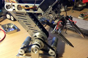
    The gripper surprised me by actually more or less working the first time. The principle of operation is that there are two jaws and two screws, one with a right-hand thread, the other left-handed. A stepper drives one screw, while a belt turns the other screw in the same direction. Each jaw is tapped for one screw and has a clearance hole for the other one. Turn the drive shaft, and the jaws move either towards each other or apart, at the same rate. The nice thing about this (it's what's known as a "parallel gripper") is that the jaws only move in one axis. With other common gripper types like a 4-link or angular gripper, the jaws move not only back and forth as they open and close, but also forward and backward. So if you want to grip a 3-inch object, the arm position would be slightly different than if you were gripping a 1-inch object located in the same place (generally speaking--there are a ton of different designs). 

    Because the screws supply an 18:1 reduction, a relatively small motor can provide a lot of grip force. Pneumatics are another way to do this, and their force:weight ratio can be excellent, but I wanted an all-electric design for a lot of reasons. I also picked up a small force-sensitive resistor (FSR). This is a neat little component whose resistance changes depending on the amount of force placed on a very thin circular pad. My plan is to integrate a stepper drive, mini Arduino, and the FSR together so that I can send the gripper commands like "open all the way," "set jaws 2 inches apart," "close until light contact," or "close until heavy contact," etc.

    The only rain on this parade is that after assembling the gripper, there's just enough drag in the whole assembly that the NEMA11 motor may not be quite enough. I'll just have to test it. If not, an upgrade will be in order. It may also be possible to get better results by improving the alignment and setup of the mechanics, or by using better bearings. As with some other parts, I'm using 608ZZ skate bearings because they're dirt-cheap, but these aren't the smoothest. 

  • It's All In The Wrist

    Colin Kingsbury08/27/2014 at 02:01 0 comments

    This project continues to deliver DUH! moments. The first three joints of the arm--you can think of them as the waist, shoulder, and elbow in human terms--came together pretty quickly and easily. They're large, and there's plenty of room to locate motors, bearings, and such. But the wrist proved to be a whole other matter entirely.

    This should have been obvious, because mechanically it's the most complicated part of the arm. There's three rotary axes, and because it's all hanging out on the end of the arm (where you're trading against payload ounce-for-ounce), there's pressure to keep it relatively small and light. Oh, and remember, I'm trying to keep this as cheap as possible, too, so that means no fancy internal gears or other goodies that cost $100 a pop.

    The design I ended up with (which you can see mostly finished in one of the pictures) is functional but one that I think will bear a lot of refinement. The motor for one of the axes is hanging off the side, and I suspect the wiring will be a bit of a rat's nest. I haven't even tried working out limit/home switches yet, but think I'll be able to find a place for them. There's also a lot of bearings involved, which add a lot of weight. On the plus side, they're all super-cheap. When the dust settles, I think it's going to eat up a good deal of payload, so I will probably be tempted to go back and see if I can reduce the weight enough to matter. The real solution may be to add more torque at the elbow and shoulder, which have the hardest job.

  • Testing the Payload, Keeping Costs Low

    Colin Kingsbury08/22/2014 at 18:28 0 comments

    Generally speaking, more payload is a Good Thing, as is more reach. Thing is, both of them increase the amount of torque needed at the two main arm joints (think shoulder and elbow). When you price steppers, higher torque means more money, and more amps, which means the drivers cost more, and it's not perfectly linear. If you can stay under 2A or so, you can use drives like the Pololu ones at around $15 each. Go to 3A, and you're spending $50-$70 for eBay specials or Gecko drives that are good for 3.5-4A. Go above that, and you're getting into $100+ for the drive, and $70 or more for the motor. It would be easy to hit a price target of $2500 or so, but in the long run I'd like to get this under $1000 in quantity, which means peeling the Lincoln heads off every penny.

    So to keep the cost down, the first round design uses 425oz-in NEMA23 motors for the two "heavy" joints, with reduction gearing to get the effective torque to where my calculations say it needs to be. It's a balance as the gearing adds non-trivial costs of its own, but I'm going with it for now.

    I decided to start by building these two joints so I could do a (literal) load test to find out if my torque calculations were correct. The video linked to the right shows the arm lifting some very pricey calibrated loads that total about 36 ounces, which exceeded the target of 32. This gave me enough confidence to continue on to one of the most mechanically-challenging parts, the wrist, which needs to incorporate three axes of motion in a 5" cube.

View all 10 project logs

Enjoy this project?

Share

Discussions

G. Rosa wrote 09/09/2021 at 14:41 point

Great job putting together the PUMA-type robotic arm.  It certainly looks professional and certainly has an industrial look to it.  Are you using the VAL programming language to operate it? 

  Are you sure? yes | no

kdoney wrote 07/17/2017 at 12:42 point

Where's the code?

  Are you sure? yes | no

Zazakas wrote 06/27/2017 at 01:51 point

Amazing Job! I also wanna build a robot like this. Do you have account on github that I can follow?

  Are you sure? yes | no

Garrett Herschleb wrote 10/29/2016 at 14:46 point

It's been a while since an update on this arm. How's it going?

  Are you sure? yes | no

Colin Kingsbury wrote 11/04/2016 at 03:41 point

Hey Garrett, I've been doing a lot of work but not updating much, so I just posted a log above. Thanks for asking!

  Are you sure? yes | no

Tonkabot wrote 01/21/2015 at 22:28 point

Opps, it is actually a Puma 560 not a 600. It's been a while.

http://bobodyne.com/web-docs/robots/Puma560/Garage.jpg

  Are you sure? yes | no

Tonkabot wrote 01/21/2015 at 21:20 point

I actually have a working PUMA 600. It has this enormous DEC PDP-11 'minicomputer' that controls it. If I ever have time to play with it I would be tempted to throw away the DEC and use a modern computer to run it.

  Are you sure? yes | no

Colin Kingsbury wrote 01/21/2015 at 21:47 point

A PDP-11? That's a real classic. I'd hate to toss it if it was working--I'll bet someone would gladly take it off your hands. Beyond that I would probably look into LinuxCNC as it has at least a couple people using it to run those, or at least a PUMA 560. I'm largely looking in another direction for my own reasons but it might be a good solution for you. Thanks for stopping by!

  Are you sure? yes | no

Garrett Herschleb wrote 12/09/2014 at 22:10 point
You might take a look at PyUltimateRobot as an alternative to LinuxCNC. PyUltimateRobot combines control of any arbitrarily segmented arm with machine vision precision.

  Are you sure? yes | no

Garrett Herschleb wrote 12/09/2014 at 22:04 point
Beautifully done metal work. How did you get it so that it looks like the metal was custom molded for your arm?

  Are you sure? yes | no

Colin Kingsbury wrote 12/09/2014 at 22:08 point
Thanks Garrett. I have a Tormach CNC mill, so I'm making the parts from scratch myself.

  Are you sure? yes | no

Similar Projects

Does this project spark your interest?

Become a member to follow this project and never miss any updates