-
Varying the Voltage to the Electromagnets
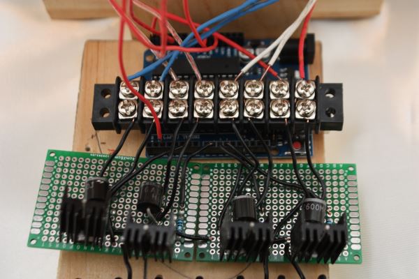
10/16/2017 at 04:14 • 0 commentsI needed a way to vary the voltage going to the electromagnet. I immediately thought of using a digital potentiometer. When I bought my first digital potentiometer IC, I realized that it couldn't handle the current needed for the electromagnet. I bought a couple that could handle the current, but they were all made for PCBs, and I had no experience with printing PCBs. Therefore, I needed to find a new way to accomplish this task. I decided to use a transistor and a PWM signal from the Arduino. I tried about 10 different transistors. I finally found one that could handle the current going to electromagnet. It got really hot so I had to use liquid silicon and a heatsink to cool the transistor.
![]()
-
Power Supply
10/16/2017 at 04:10 • 0 commentsI needed an adequate power supply that could give enough voltage to the electromagnets. I started with a 9 volt battery but this didn't have enough power. I then tried to use a computer power supply. Although, this had enough voltage, it was not safe to use in the long run.
I then decided to invest in a professional 12 volt power supply. This protected against short circuits and was perfect for my purposes!
-
Developing the Electromagnet
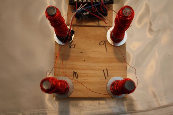
10/16/2017 at 04:07 • 0 commentsI needed to create electromagnets that could lift a platform. I started experimenting by using 32 gauge wire wrapped around a screwdriver. This did not have nearly enough lifting force. I tried to wrap it around a bolt instead, but this did not help.
![]()
I used this formula to try to refind my electromagnet. I found that I need wires of less resistance. Thus, I used 24 gauge wire wrapped around a bolt 500 times. This created about 10 N of force.
![]()
-
MPU-6050
10/16/2017 at 04:02 • 0 commentsThis was my first attempt at an electronics project. I had never soldered before. I had never wired anything. I had never used a breadboard. Thus, everything was really foreign to me. I looked up how to wire the MPU-6050 accelerometer and found this:
![]()
When I first connected it, I found that the light turned on but I couldn't get any data. After several days of troubleshooting, I found that I couldn't maintain a stable connection. Therefore, I realized that I had to solder the pins. Then I uploaded this code:
// I2Cdev and MPU6050 must be installed as libraries, or else the .cpp/.h files
// for both classes must be in the include path of your project
#include "I2Cdev.h"
#include "MPU6050_6Axis_MotionApps20.h"
//#include "MPU6050.h" // not necessary if using MotionApps include file
// Arduino Wire library is required if I2Cdev I2CDEV_ARDUINO_WIRE implementation
// is used in I2Cdev.h
#if I2CDEV_IMPLEMENTATION == I2CDEV_ARDUINO_WIRE
    #include "Wire.h"
#endif
// class default I2C address is 0x68
// specific I2C addresses may be passed as a parameter here
// AD0 low = 0x68 (default for SparkFun breakout and InvenSense evaluation board)
// AD0 high = 0x69
MPU6050 mpu;
//MPU6050 mpu(0x69); // <-- use for AD0 high
/* =========================================================================
   NOTE: In addition to connection 3.3v, GND, SDA, and SCL, this sketch
   depends on the MPU-6050's INT pin being connected to the Arduino's
   external interrupt #0 pin. On the Arduino Uno and Mega 2560, this is
   digital I/O pin 2.
 * ========================================================================= */
/* =========================================================================
   NOTE: Arduino v1.0.1 with the Leonardo board generates a compile error
   when using Serial.write(buf, len). The Teapot output uses this method.
   The solution requires a modification to the Arduino USBAPI.h file, which
   is fortunately simple, but annoying. This will be fixed in the next IDE
   release. For more info, see these links:
   http://arduino.cc/forum/index.php/topic,109987.0.html
   http://code.google.com/p/arduino/issues/detail?id=958
 * ========================================================================= */
// uncomment "OUTPUT_READABLE_QUATERNION" if you want to see the actual
// quaternion components in a [w, x, y, z] format (not best for parsing
// on a remote host such as Processing or something though)
//#define OUTPUT_READABLE_QUATERNION
// uncomment "OUTPUT_READABLE_EULER" if you want to see Euler angles
// (in degrees) calculated from the quaternions coming from the FIFO.
// Note that Euler angles suffer from gimbal lock (for more info, see
// http://en.wikipedia.org/wiki/Gimbal_lock)
//#define OUTPUT_READABLE_EULER
// uncomment "OUTPUT_READABLE_YAWPITCHROLL" if you want to see the yaw/
// pitch/roll angles (in degrees) calculated from the quaternions coming
// from the FIFO. Note this also requires gravity vector calculations.
// Also note that yaw/pitch/roll angles suffer from gimbal lock (for
// more info, see: http://en.wikipedia.org/wiki/Gimbal_lock)
#define OUTPUT_READABLE_YAWPITCHROLL
// uncomment "OUTPUT_READABLE_REALACCEL" if you want to see acceleration
// components with gravity removed. This acceleration reference frame is
// not compensated for orientation, so +X is always +X according to the
// sensor, just without the effects of gravity. If you want acceleration
// compensated for orientation, us OUTPUT_READABLE_WORLDACCEL instead.
//#define OUTPUT_READABLE_REALACCEL
// uncomment "OUTPUT_READABLE_WORLDACCEL" if you want to see acceleration
// components with gravity removed and adjusted for the world frame of
// reference (yaw is relative to initial orientation, since no magnetometer
// is present in this case). Could be quite handy in some cases.
//#define OUTPUT_READABLE_WORLDACCEL
// uncomment "OUTPUT_TEAPOT" if you want output that matches the
// format used for the InvenSense teapot demo
//#define OUTPUT_TEAPOT
#define INTERRUPT_PIN 2  // use pin 2 on Arduino Uno & most boards
#define LED_PIN 13 // (Arduino is 13, Teensy is 11, Teensy++ is 6)
bool blinkState = false;
// MPU control/status vars
bool dmpReady = false;  // set true if DMP init was successful
uint8_t mpuIntStatus;   // holds actual interrupt status byte from MPU
uint8_t devStatus;      // return status after each device operation (0 = success, !0 = error)
uint16_t packetSize;    // expected DMP packet size (default is 42 bytes)
uint16_t fifoCount;     // count of all bytes currently in FIFO
uint8_t fifoBuffer[64]; // FIFO storage buffer
// orientation/motion vars
Quaternion q;           // [w, x, y, z]         quaternion container
VectorInt16 aa;         // [x, y, z]            accel sensor measurements
VectorInt16 aaReal;     // [x, y, z]            gravity-free accel sensor measurements
VectorInt16 aaWorld;    // [x, y, z]            world-frame accel sensor measurements
VectorFloat gravity;    // [x, y, z]            gravity vector
float euler[3];         // [psi, theta, phi]    Euler angle container
float ypr[3];           // [yaw, pitch, roll]   yaw/pitch/roll container and gravity vector
// packet structure for InvenSense teapot demo
uint8_t teapotPacket[14] = { '$', 0x02, 0,0, 0,0, 0,0, 0,0, 0x00, 0x00, '\r', '\n' };
// ================================================================
// ===               INTERRUPT DETECTION ROUTINE                ===
// ================================================================
volatile bool mpuInterrupt = false;     // indicates whether MPU interrupt pin has gone high
void dmpDataReady() {
    mpuInterrupt = true;
}
// ================================================================
// ===                      INITIAL SETUP                       ===
// ================================================================
void setup() {
    // join I2C bus (I2Cdev library doesn't do this automatically)
    #if I2CDEV_IMPLEMENTATION == I2CDEV_ARDUINO_WIRE
        Wire.begin();
        Wire.setClock(400000); // 400kHz I2C clock. Comment this line if having compilation difficulties
    #elif I2CDEV_IMPLEMENTATION == I2CDEV_BUILTIN_FASTWIRE
        Fastwire::setup(400, true);
    #endif
    // initialize serial communication
    // (115200 chosen because it is required for Teapot Demo output, but it's
    // really up to you depending on your project)
    Serial.begin(115200);
    while (!Serial); // wait for Leonardo enumeration, others continue immediately
    // NOTE: 8MHz or slower host processors, like the Teensy @ 3.3v or Ardunio
    // Pro Mini running at 3.3v, cannot handle this baud rate reliably due to
    // the baud timing being too misaligned with processor ticks. You must use
    // 38400 or slower in these cases, or use some kind of external separate
    // crystal solution for the UART timer.
    // initialize device
    Serial.println(F("Initializing I2C devices..."));
    mpu.initialize();
    pinMode(INTERRUPT_PIN, INPUT);
    // verify connection
    Serial.println(F("Testing device connections..."));
    Serial.println(mpu.testConnection() ? F("MPU6050 connection successful") : F("MPU6050 connection failed"));
    // wait for ready
    Serial.println(F("\nSend any character to begin DMP programming and demo: "));
    while (Serial.available() && Serial.read()); // empty buffer
    while (!Serial.available());                 // wait for data
    while (Serial.available() && Serial.read()); // empty buffer again
    // load and configure the DMP
    Serial.println(F("Initializing DMP..."));
    devStatus = mpu.dmpInitialize();
    // supply your own gyro offsets here, scaled for min sensitivity
    mpu.setXGyroOffset(220);
    mpu.setYGyroOffset(76);
    mpu.setZGyroOffset(-85);
    mpu.setZAccelOffset(1788); // 1688 factory default for my test chip
    // make sure it worked (returns 0 if so)
    if (devStatus == 0) {
        // turn on the DMP, now that it's ready
        Serial.println(F("Enabling DMP..."));
        mpu.setDMPEnabled(true);
        // enable Arduino interrupt detection
        Serial.println(F("Enabling interrupt detection (Arduino external interrupt 0)..."));
        attachInterrupt(digitalPinToInterrupt(INTERRUPT_PIN), dmpDataReady, RISING);
        mpuIntStatus = mpu.getIntStatus();
        // set our DMP Ready flag so the main loop() function knows it's okay to use it
        Serial.println(F("DMP ready! Waiting for first interrupt..."));
        dmpReady = true;
        // get expected DMP packet size for later comparison
        packetSize = mpu.dmpGetFIFOPacketSize();
    } else {
        // ERROR!
        // 1 = initial memory load failed
        // 2 = DMP configuration updates failed
        // (if it's going to break, usually the code will be 1)
        Serial.print(F("DMP Initialization failed (code "));
        Serial.print(devStatus);
        Serial.println(F(")"));
    }
    // configure LED for output
    pinMode(LED_PIN, OUTPUT);
}
// ================================================================
// ===                    MAIN PROGRAM LOOP                     ===
// ================================================================
void loop() {
    // if programming failed, don't try to do anything
    if (!dmpReady) return;
    // wait for MPU interrupt or extra packet(s) available
    while (!mpuInterrupt && fifoCount < packetSize) {
        // other program behavior stuff here
        // .
        // .
        // .
        // if you are really paranoid you can frequently test in between other
        // stuff to see if mpuInterrupt is true, and if so, "break;" from the
        // while() loop to immediately process the MPU data
        // .
        // .
        // .
    }
    // reset interrupt flag and get INT_STATUS byte
    mpuInterrupt = false;
    mpuIntStatus = mpu.getIntStatus();
    // get current FIFO count
    fifoCount = mpu.getFIFOCount();
    // check for overflow (this should never happen unless our code is too inefficient)
    if ((mpuIntStatus & 0x10) || fifoCount == 1024) {
        // reset so we can continue cleanly
        mpu.resetFIFO();
        Serial.println(F("FIFO overflow!"));
    // otherwise, check for DMP data ready interrupt (this should happen frequently)
    } else if (mpuIntStatus & 0x02) {
        // wait for correct available data length, should be a VERY short wait
        while (fifoCount < packetSize) fifoCount = mpu.getFIFOCount();
        // read a packet from FIFO
        mpu.getFIFOBytes(fifoBuffer, packetSize);

        // track FIFO count here in case there is > 1 packet available
        // (this lets us immediately read more without waiting for an interrupt)
        fifoCount -= packetSize;
        #ifdef OUTPUT_READABLE_QUATERNION
            // display quaternion values in easy matrix form: w x y z
            mpu.dmpGetQuaternion(&q, fifoBuffer);
            Serial.print("quat\t");
            Serial.print(q.w);
            Serial.print("\t");
            Serial.print(q.x);
            Serial.print("\t");
            Serial.print(q.y);
            Serial.print("\t");
            Serial.println(q.z);
        #endif
        #ifdef OUTPUT_READABLE_EULER
            // display Euler angles in degrees
            mpu.dmpGetQuaternion(&q, fifoBuffer);
            mpu.dmpGetEuler(euler, &q);
            Serial.print("euler\t");
            Serial.print(euler[0] * 180/M_PI);
            Serial.print("\t");
            Serial.print(euler[1] * 180/M_PI);
            Serial.print("\t");
            Serial.println(euler[2] * 180/M_PI);
        #endif
        #ifdef OUTPUT_READABLE_YAWPITCHROLL
            // display Euler angles in degrees
            mpu.dmpGetQuaternion(&q, fifoBuffer);
            mpu.dmpGetGravity(&gravity, &q);
            mpu.dmpGetYawPitchRoll(ypr, &q, &gravity);
            Serial.print("ypr\t");
            Serial.print(ypr[0] * 180/M_PI);
            Serial.print("\t");
            Serial.print(ypr[1] * 180/M_PI);
            Serial.print("\t");
            Serial.println(ypr[2] * 180/M_PI);
        #endif
        #ifdef OUTPUT_READABLE_REALACCEL
            // display real acceleration, adjusted to remove gravity
            mpu.dmpGetQuaternion(&q, fifoBuffer);
            mpu.dmpGetAccel(&aa, fifoBuffer);
            mpu.dmpGetGravity(&gravity, &q);
            mpu.dmpGetLinearAccel(&aaReal, &aa, &gravity);
            Serial.print("areal\t");
            Serial.print(aaReal.x);
            Serial.print("\t");
            Serial.print(aaReal.y);
            Serial.print("\t");
            Serial.println(aaReal.z);
        #endif
        #ifdef OUTPUT_READABLE_WORLDACCEL
            // display initial world-frame acceleration, adjusted to remove gravity
            // and rotated based on known orientation from quaternion
            mpu.dmpGetQuaternion(&q, fifoBuffer);
            mpu.dmpGetAccel(&aa, fifoBuffer);
            mpu.dmpGetGravity(&gravity, &q);
            mpu.dmpGetLinearAccel(&aaReal, &aa, &gravity);
            mpu.dmpGetLinearAccelInWorld(&aaWorld, &aaReal, &q);
            Serial.print("aworld\t");
            Serial.print(aaWorld.x);
            Serial.print("\t");
            Serial.print(aaWorld.y);
            Serial.print("\t");
            Serial.println(aaWorld.z);
        #endif

        #ifdef OUTPUT_TEAPOT
            // display quaternion values in InvenSense Teapot demo format:
            teapotPacket[2] = fifoBuffer[0];
            teapotPacket[3] = fifoBuffer[1];
            teapotPacket[4] = fifoBuffer[4];
            teapotPacket[5] = fifoBuffer[5];
            teapotPacket[6] = fifoBuffer[8];
            teapotPacket[7] = fifoBuffer[9];
            teapotPacket[8] = fifoBuffer[12];
            teapotPacket[9] = fifoBuffer[13];
            Serial.write(teapotPacket, 14);
            teapotPacket[11]++; // packetCount, loops at 0xFF on purpose
        #endif
        // blink LED to indicate activity
        blinkState = !blinkState;
        digitalWrite(LED_PIN, blinkState);
    }
}
Electromagnetic Levitation Stabilization Apparatus
This project aims to stabilize objects during earthquakes using electromagnets and an accelerometer.