Close
0%
0%

Micro:Boy

Arcade games on the Micro:bit

Similar projects worth following

The Micro:bit is a pretty decent platform for teaching kids to program, but you can't really make arcade-style games for it. You only have two buttons and a 5x5 display. Perhaps enough for a very small snake game, but that's pretty much it. That's why I started working on #PewPew FeatherWing as an alternative platform, but at some point I started wondering if it's really impossible to do it on the micro:bit.

When the most recent version of micropython got the ability to use any pins for I2C, I realized that I can finally connect a display easily. I could use a HT16K33 and a 8x8 LED matrix like on the PewPew, but I decided to try something else — a monochrome OLED display, similar to the one used on many Arduino-based game consoles.

  • 1 × 1.3" OLED SH1106 I²C module
  • 1 × ATTiny24 Microprocessors, Microcontrollers, DSPs / ARM, RISC-Based Microcontrollers
  • 1 × SPDT switch
  • 1 × piezo speaker
  • 6 × 6x6mm tact switch, smd

View all 10 components

  • MemoryError

    deʃhipu01/25/2018 at 22:36 0 comments

    So I got that Boulder Dash game as far as I can, working around the ridiculously low memory of Micro:bit, and I think I won't be able to go further. This platform is simply too puny.

    I have an animated player character digging tunnels, and I have boulders that block his way and fall into empty space you dig under them. And I can't add even a single line of code without getting a MemoryError.

    Read more »

  • Progress on a Game

    deʃhipu01/20/2018 at 00:41 0 comments

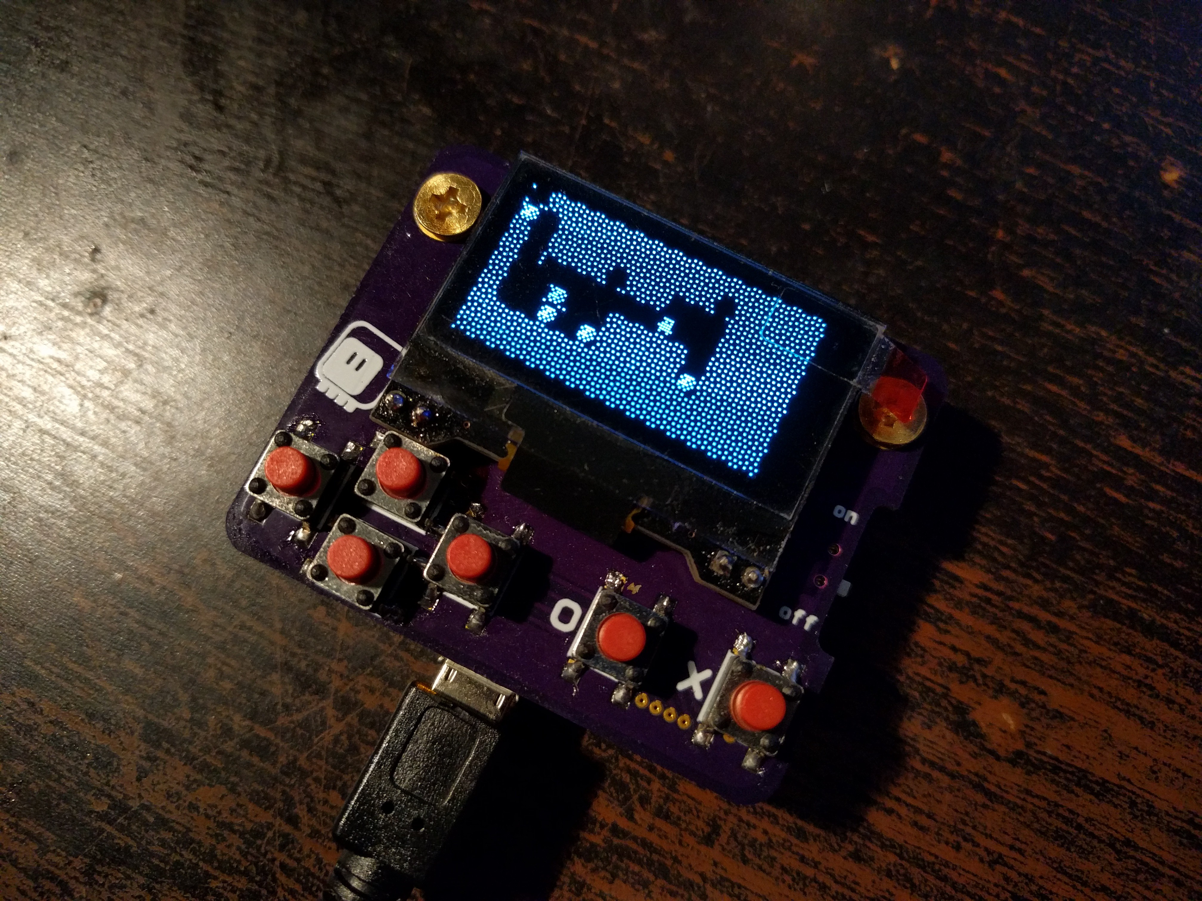
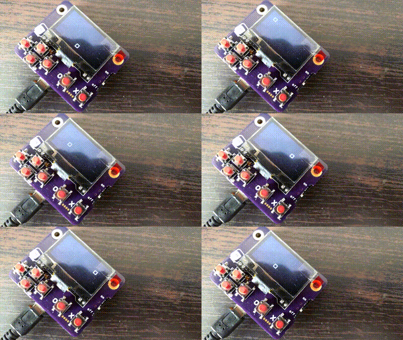
    With the hardware finalized, the remaining work is to actually write at least one game, to prove that it's possible. I decided to make a game inspired by such classics as Dig Dug, Digger and Boulder Dash — you dig tunnels, collect gems, avoid monsters and drop boulders on them. So far I have the basic graphics and the player animation:

    Read more »

  • Why Separate Button Controller?

    deʃhipu01/18/2018 at 10:23 0 comments

    I have been asked why I'm using a separate chip for handling the buttons, so I thought I will just explain it in here. The question was why not just use the edge connector, and then use the additional pins available on the Micro:bit for reading the buttons. There are actually to reasons for that:

    I don't like the edge connector.

    Ever since I first saw it, I tried to work around it with something smaller, lighter and less expensive — you can look at my #Micro:header — but I never managed to get a reliable connection without damaging the Micro:bit itself. I do have a bunch of those connectors, both soldered on a breakout board, and loose, but they are simply too large for such a small handheld device, I don't have a Fritzing footprint for them (and don't feel like making one), and soldering all the pins is a chore. Bolts are, on the other hand, a tested and reliable alternative.

    Handling buttons is not trivial.

    Looking at the code for the button controller you wouldn't guess that, but handling the button presses properly is actually a non-trivial task. You have to de-bounce them, and you have to buffer them — those are some simple things we came to expect from anything with buttons, because it's so common. Doing that in the limited version of Micropython that runs on the Micro:bit, without access to timers or interrupts, while at the same time handling the logic of whatever game you are playing would be a challenge, if not outright impossible. Doing it in C as a built-in module would be a little easier (that's how I did it for #µGame), but getting that extra code merged and released would take ages — the current release is a year behind, and there is never enough memory, so I don't think they would happily accept an extra module that is only useful in one project. Having to use a custom Micropython firmware would make it impossible to code using Mu or any of the other dedicated editors.

    So considering all that, I decided to use a dedicated chip for the buttons. I initially started with a simple gpio expander chip, like in #D1 Mini X-Pad Shield, but that still requires you to poll it constantly and do the de-bouncing and buffering yourself. You can also easily miss presses. Then I switched to the HT16K33 that I'm using in #PewPew FeatherWing, because it does the de-bouncing and buffering for you, but that's an expensive and bulky chip, that we are not really fully utilizing. So I looked for the cheapest microcontroller with enough pins, and ATtiny24 seems like the perfect fit, especially since I already have experience with AVR.

  • Button Controller

    deʃhipu01/17/2018 at 18:53 0 comments

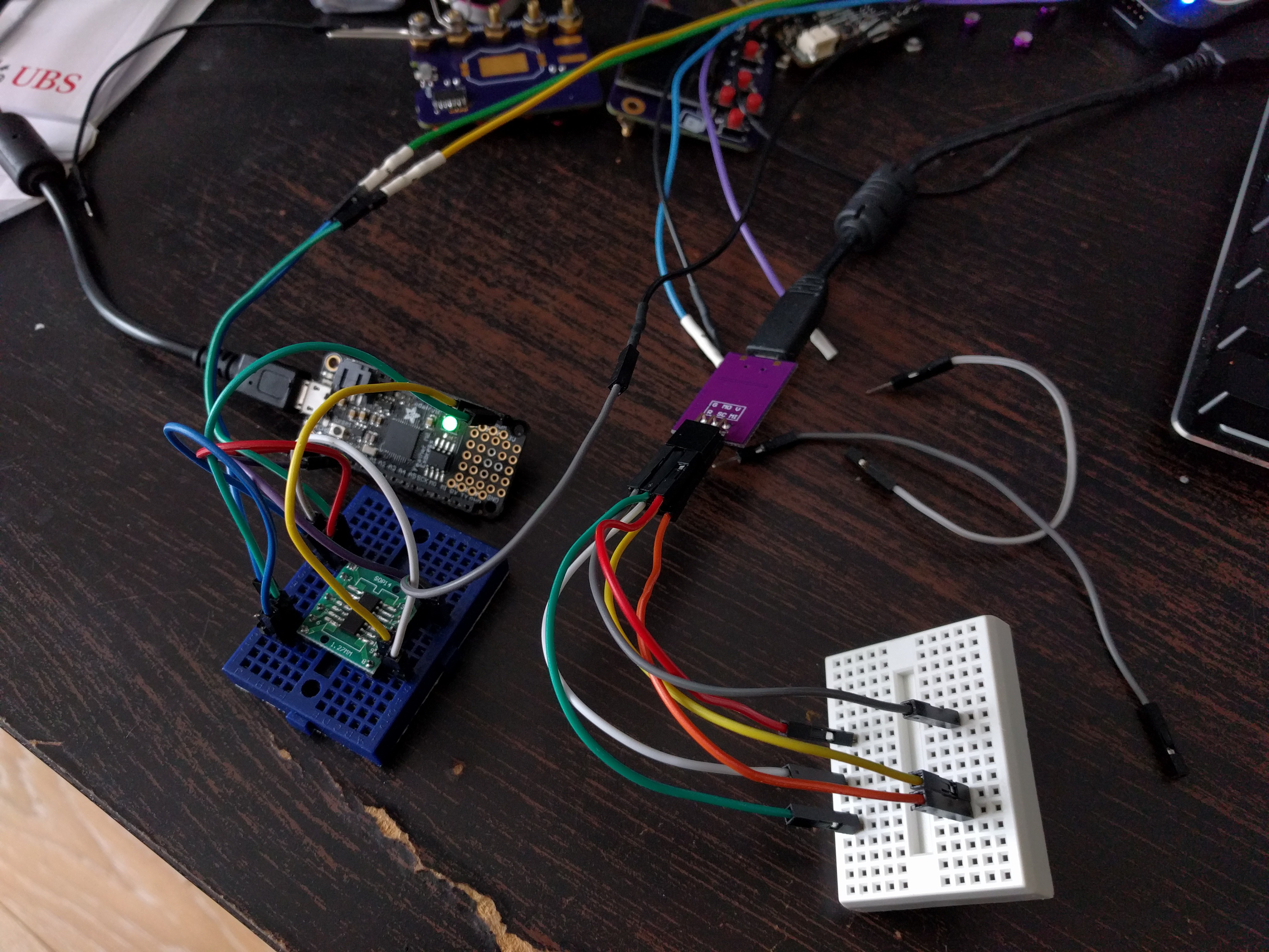
    The ATtiny24A chips I ordered finally arrived yesterday, and I could start working on the firmware for the button controller. I quickly assembled a setup for experimenting:

    One mini-breadboard for programming, one for testing the I2C (since programming uses the same pins, and I2C needs the pullup resistors, it would be hard to have everything on one board). The chip is on a breakout board for easy plugging. An Adafruit Feather M0 Express plays the role of the I2C master. Some additional wires for the logic analyzer complete the setup.

    Read more »

  • Advanced Spriting

    deʃhipu01/09/2018 at 13:51 0 comments

    After a nightfull of sleep, I realized that I don't need a separate method with "or" for proper non-transparent sprites, since if I'm masking the place with black anyways, "xor" works just as well. As an added bonus, I can have also parts of the sprite sticking out of the mask outline, which then will be xor-ed, which could be a nice effect. I also decided to use "nand" for the mask, not "and", since then the outline of the sprite is white and the background is black, and that works better with the shifting operators. Finally, I made the mask just an optional argument to the blit function, since you are not likely to use it alone. So I have this:

    I had to add one more thing, of which I didn't think before. When not using "xor" for the sprite, I need some way to restore the previous background when the sprite moves away. Right now I'm using an inefficient method of simply keeping a copy of the background in a separate buffer, and simply copying the few bytes where the sprite used to be from it to the actual frame buffer (and updating the dirty numbers accordingly). A more efficient way could be imagined.

    Read more »

  • Blit

    deʃhipu01/08/2018 at 13:21 0 comments

    I'm still waiting for the attiny chips for the button handling, but I realized that my display driver is not really suitable for making games. Sure, it has that cool dirty pages stuff that makes it fast, but it only can draw a pixel at a time. That's not how you are going to get nice smooth animations. We need a blit operation — something that will let me draw a whole sprite in one operation.

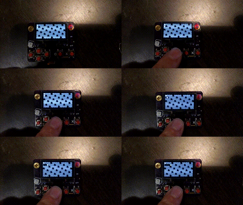
    The way blit works, it takes whole bytes, shifts them as required, and combines with the current frame buffer using one of the logic operators. For a start I have chosen xor. Why? Because that's the easiest way to have sprites that don't delete the background as they move around — you blit them once to show them, and you blit them a second time to make them disappear. Sure, they don't look pretty when they collide with something, but it's a start. Later I can do similar operations with or and and, so that I can have pretty sprites with a mask. For now I have a bouncing box:

    This is done with this code:

    Read more »

  • Some Progress

    deʃhipu01/07/2018 at 21:21 0 comments

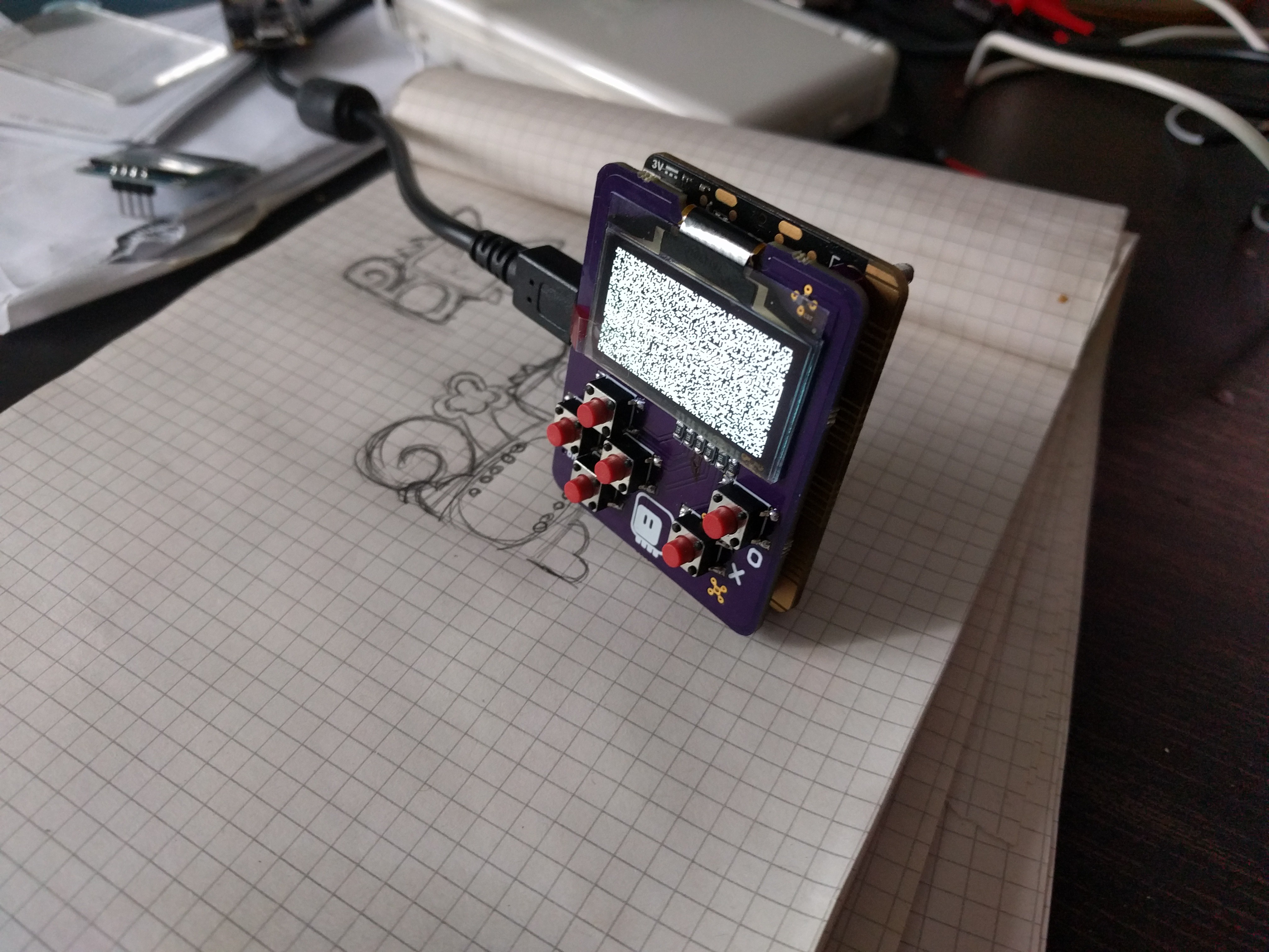
    The PCBs with the horizontal layout and display module arrived, so I assembled the new version:

    I'm happy with it mechanically. You don't touch the contacts when you hold it, and the two buttons on the micro:bit are right under your index fingers. It's wide enough to hold comfortably. The flattened d-pad is a bit less convenient than it could be if it was full-size, but I can't have everything. The coin battery fits inside the sandwich, and the whole thing the right thickness. I had to add some spacers to the bolts that hold the thing together, to make sure the spacing is right. You can both use through-hole bolts, or solder them to the pads — here I soldered them, but I think I will go with through-hole in the future.

    I'm still missing one crucial part — the attiny that will be handling the buttons is still on the slow boat from China. Seems like the holiday season was really tough on the post offices around the world, because everything takes longer now. I guess I won't be able to get this to work before the contest deadline.

    On an unrelated note, I think I figured out why I couldn't get that display to work reliably without a module. Turns out that after powering it, it requires to be reset by the physical reset pin. The datasheet's example schematics don't show it, but those modules have an R-C circuit on the reset pin to do that. Mine didn't, hence the problems. But I think I will stay with the modules for now anyways.

  • After All it Works!

    deʃhipu12/17/2017 at 19:45 0 comments

    I have re-read what I wrote in my previous log, and got that "wait a minute" moment. I'm using a circuit literally copied from the datasheet. All connections are correct.  There is I2C communication. It just doesn't display anything. Perhaps it's the display that is broken? So I tried with another display, and lo and behold! It works!

    To be honest, I don't think the display arrived broken — I think I broke it with my initial tries, when the components were taken from the SSD1306 datasheet, instead of the SH1106.

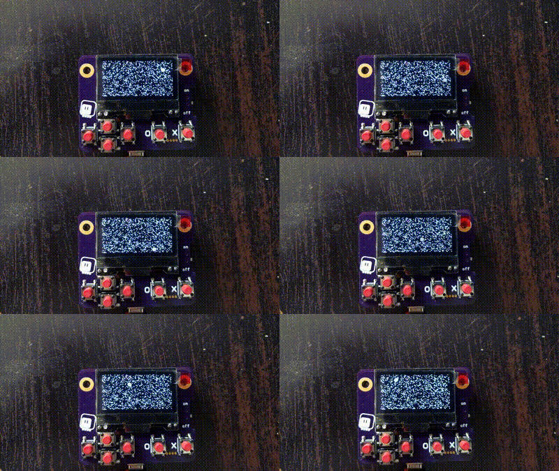
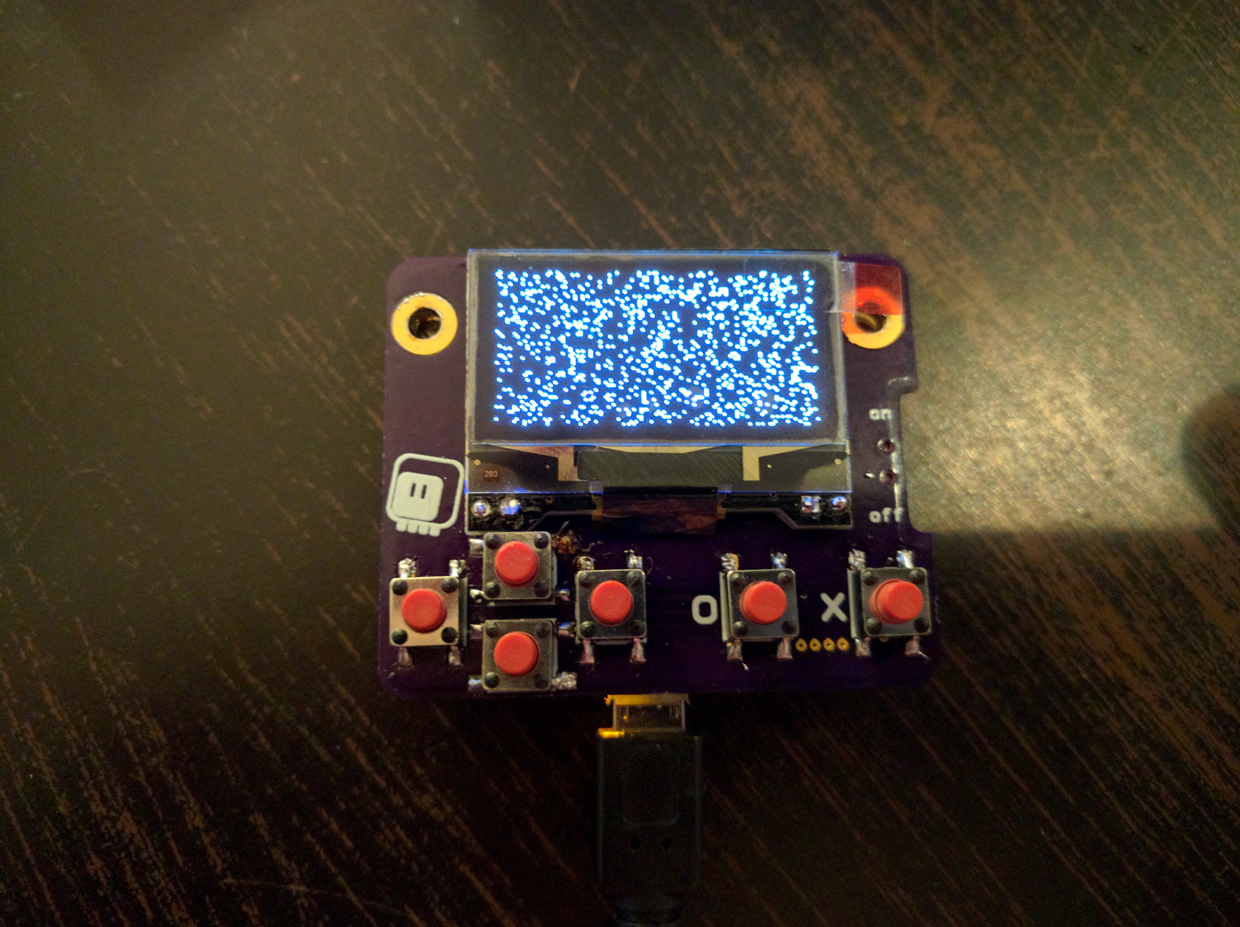
    But if the display works, that means I can assemble the whole thing and start programming for it! I quickly added all the remaining components, programmed the micro:bit with the "fill the display with random dots" demo, and it works:

    I even added the function to read the button states:

    def buttons():
        microbit.i2c.write(0x70, b'\x40', repeat=True)
        buttons = microbit.i2c.read(0x70, 2)
        return buttons[0] >> 7 | buttons[1] << 1

    And I have all that is needed for simple games. For more complex games, I still need to implement the "blit" method — or three, for and, or, and xor. 

    I'm still fine with the redesign I described in the previous log, though — this layout has one large problem: the micro:bit connectors are right under your fingers, including the i2c signals — and when you touch them, you get communication errors with the display. Switching to horizontal layout not only moves the connections out of the reach, but also makes it easy to use the two buttons on the back, so  think it's better, even though the direction buttons are a little bit more squashed.

  • Restart

    deʃhipu12/15/2017 at 21:07 0 comments

    I didn't manage to get that display to work, even though the circuit is copied directly from the datasheet.  Interestingly, the modules with this display that I have use completely different values for all the components than the datasheet says — I tried with those too, to no avail. So I decided to take a step back and do it the easier way.

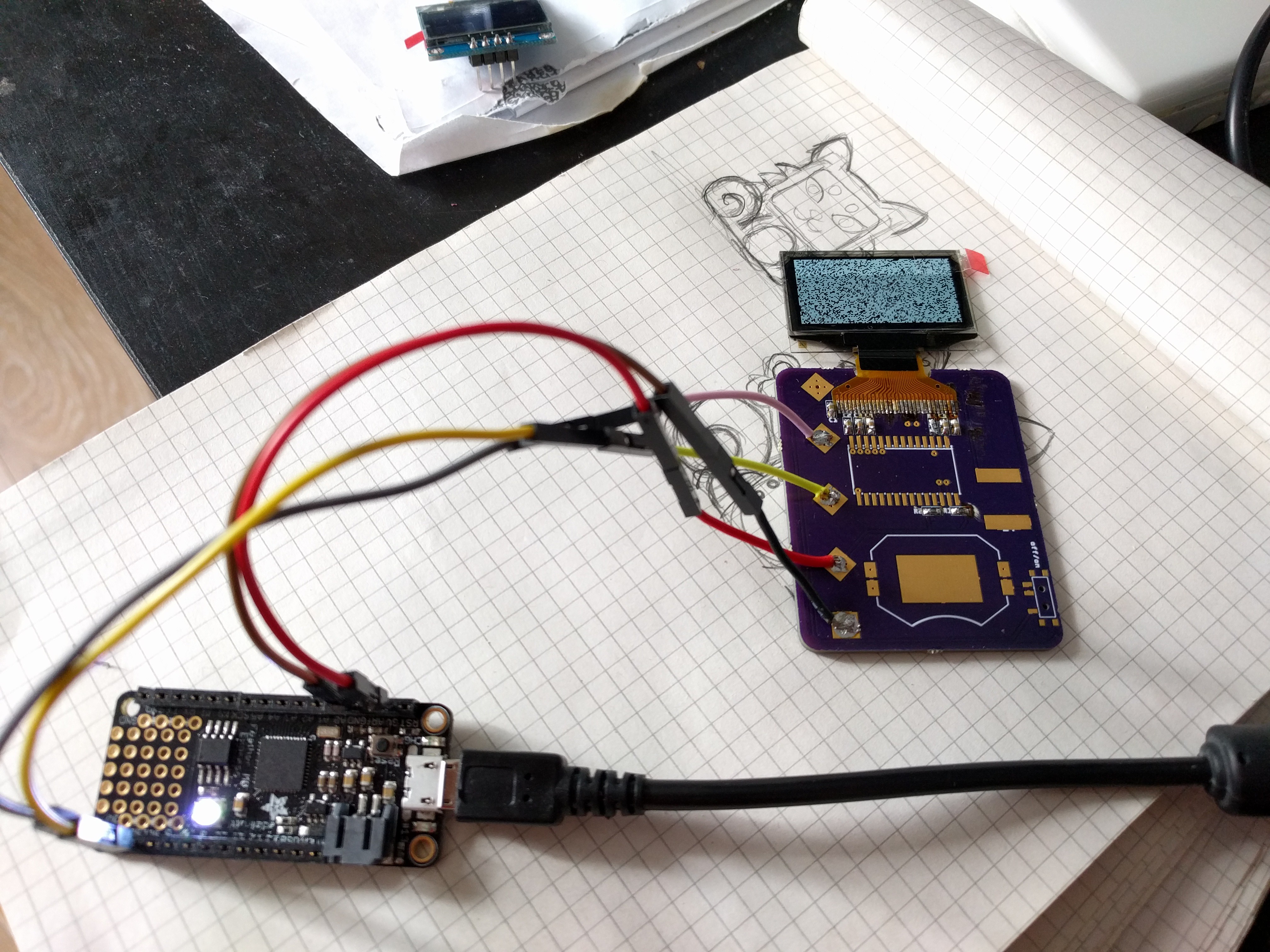
    There is a very small, minimalist module with this display designed as a shield for one of the new ESP32 boards, that will work just fine for my purposes. It already has all the needed components and it's working, so I will just use that. In addition, because now I have the display on a separate PCB, I can stack that PCB over the bolts, so I can use regular holes for the bolts, and change the orientation of the whole device, so that the A and B buttons of the micro:bit can also be used as shoulder buttons.

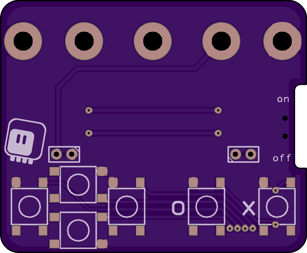
    The PCB looks like this:

    I also decided to use an ATtiny24 for handling the buttons — this way I can write the latching code exactly the way I want it, and also do debouncing and all that internally. I briefly considering just using the analog pin and a bunch of resistors for the buttons, but I don't trust those bolt connections.

  • Special Bolts

    deʃhipu11/30/2017 at 00:07 0 comments

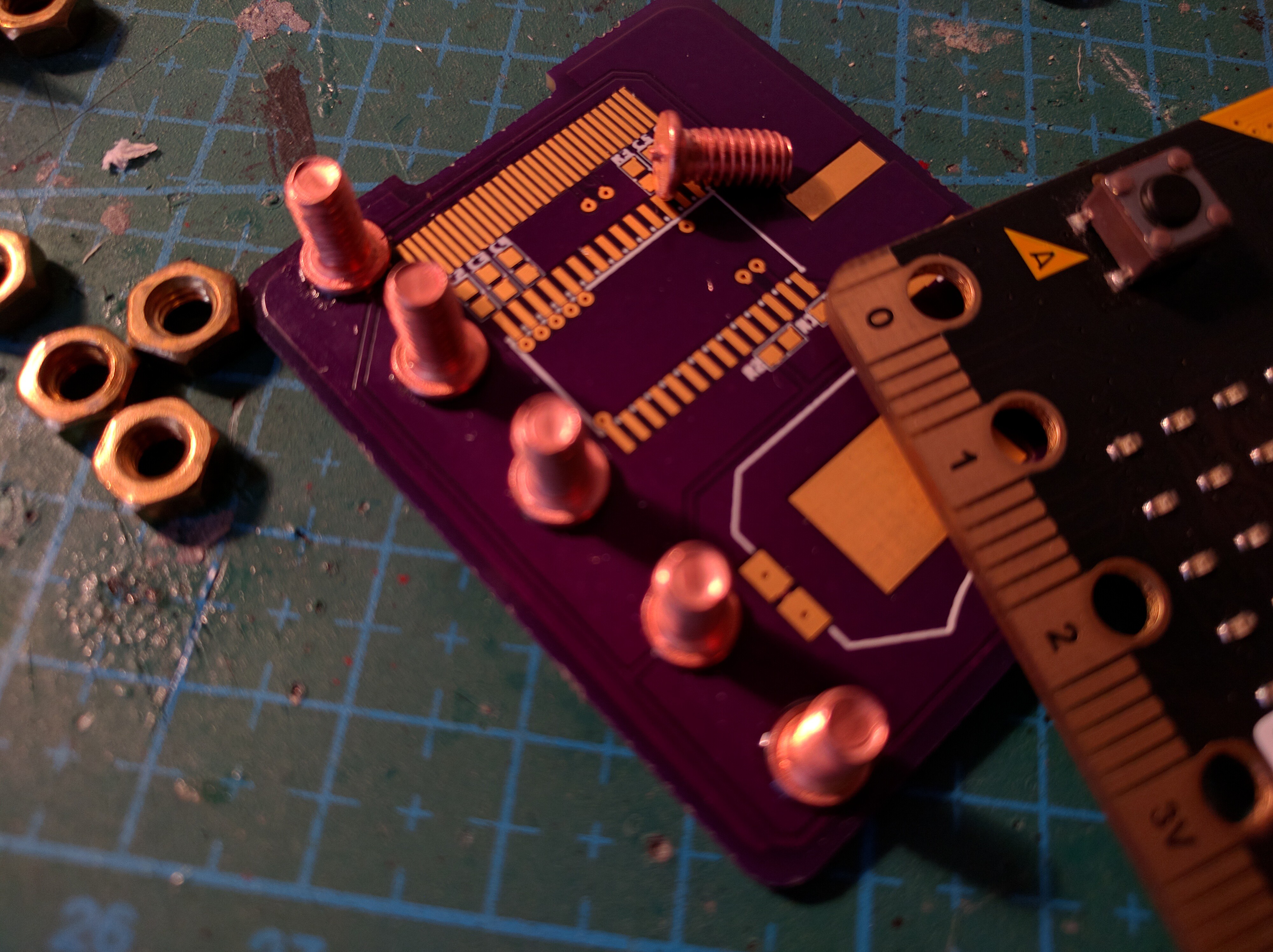
    The special bolts arrived this weekend, and I got to try them:

    The good things about them: they are exactly the right size of the micro:bit's holes, they are made specially for soldering onto the PCB, they have this small pilot nub in the center, that lets you give them an exact position. The bad things: you have to be careful to make them exactly vertical, or the micro:bit won't fit on them, the standard nuts are too big and short neighboring pins (I need to find some kind of washers for them), they take somewhat long to heat up enough to melt the solder.

    In other news, I'm still struggling with getting the screen to work. I might switch to a ready module at some point.

View all 13 project logs

Enjoy this project?

Share

Discussions

davedarko wrote 01/17/2018 at 20:45 point

Best. Micro:bit. Project. Ever. :)

  Are you sure? yes | no

deʃhipu wrote 01/17/2018 at 20:47 point

Thanks. We will see if I manage to make any game with the pathetic scraps of memory that I have left there...

  Are you sure? yes | no

Hendra Kusumah wrote 12/01/2017 at 06:32 point

I love micropython and arduboy and recently just got myself a micro:bit. And this is an awesome project that I need to do. Great project

  Are you sure? yes | no

deʃhipu wrote 01/17/2018 at 20:48 point

Thank you!

  Are you sure? yes | no

oshpark wrote 11/20/2017 at 04:42 point

Great concept!

  Are you sure? yes | no

deʃhipu wrote 01/17/2018 at 21:48 point

Thanks!

  Are you sure? yes | no

Similar Projects

Does this project spark your interest?

Become a member to follow this project and never miss any updates