-
Module Testing & Some Useful Links
11/18/2017 at 20:31 • 1 commentRange Testing
![]()
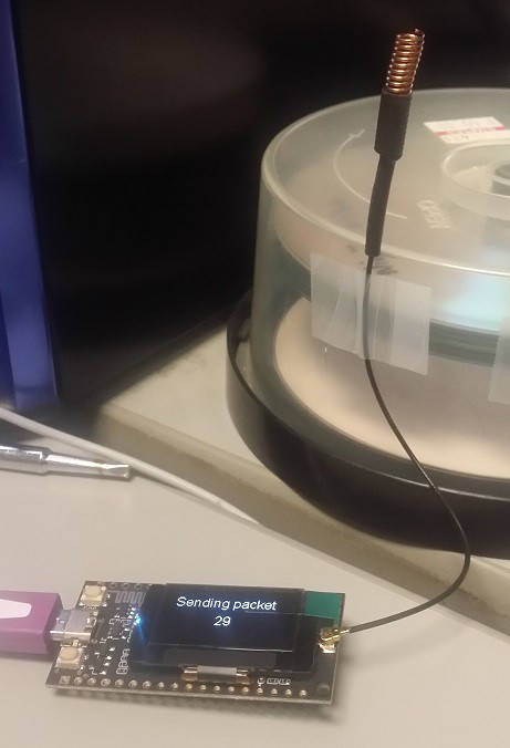
Transmitter at my desk Testing the TTGO Modules
I spent a couple of hours this morning gathering some data from my two TTGO ESP32-LoRa radios to try to determine the best settings to use to get reliable communications in weak signal conditions. For the purposes of these tests I needed a relatively poor signal path so I wouldn't have to walk too far to run out of signal. To this end I placed the module programmed as the transmitter on my desk right next to my computer. My desk is located in a cubicle on the second floor of a brick building so it is surrounded on 3 sides by the (mostly) steel cubicle walls in addition to the usual clutter of steel and brick. The remaining side (south facing) is next to a window that looks down the longest sidewalk on campus.
![Signal Path 1 Signal Path 1]()
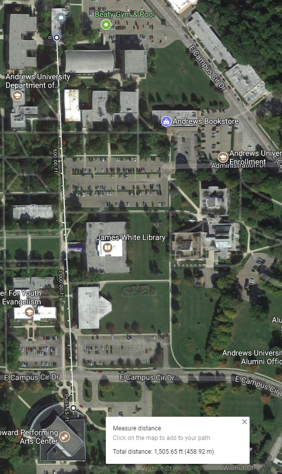
1500ft path with no solid obstructions ![Signal Path 2 Signal Path 2]()
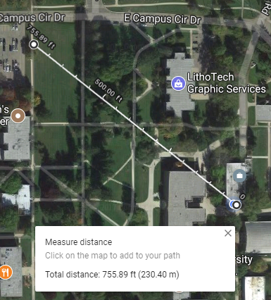
Shorter path with significant obstructions Signal Paths
I chose two signal paths for evaluation. The first is straight down the sidewalk outside my window 1500ft (457m) to the entrance of the performing arts center. Along this path there are no buildings that stand directly in the way however there are quite a few trees. The path has buildings on either side that are likely to provide for some multipath reflections. The second signal path is a more difficult one in terms of RF penetration. The far point of that path is about 750ft (228m) to the northwest of my office. Signals traversing this path must pass through the wall of my cubicle as well as that of two adjacent cubicles. In addition the signal travels through the brick wall of my building and passes through the corner of a nearby building on the way. This path has less multipath opportunities but greater signal attenuation than the first path. To make the observations I walked both paths while watching the received packets on the OLED screen of my second TTGO module.
Test SettingsFor all of the tests the transmitter was set to a center frequency of 433.000mHz with the transmitter power level of 20dBm. Neither figure was verified as I don't have the test gear to do so. The bandwidth setting of the LoRa modulator was set to 125kHz and forward error correction was set at 8/4 for all tests. The antennas used were the 'coil spring' antennas supplied with the modules. Packets consisted of my Amateur Radio callsign followed by a space, a # character, and a sequential number. They varied in length from 8 to 11 characters. I varied the LoRa spreading factor from 7 to 11 and took readings of RSSI and reported SNR from the receiver at the far end of each path. The receive antenna was held at about 1 meter off the ground and oriented vertically to match the transmitter antenna. The data are shown below:
Spreading factor RSSI (path 1) SNR (path 1) RSSI (path 2) SNR (Path 2) 7 (128 chips/bit) -114 dBm 13.25 dB -111 dBm 14.5 dB 8 (256 chips/bit) -109 dBm 14.0 dB -113 dBm 14.25 dB 9 (512 chips/bit) -105 dBm 15.5 dB -107 dBm 16.25 dB 10 (1024 chips/bit) -106 dBm 16.5 dB -105 dBm 16.75 dB 11 (2048 chips/bit) -103 dBm 17.75 dB -102 dBm 17.25 dB ![RTL-SDR display of transmitted signal RTL-SDR display of transmitted signal]()
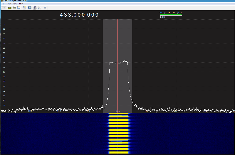
Signal as displayed by RTL-SDR (sf = 11, BW = 125Khz) Observations
While the reported signal levels and SNR figures all appeared to improve as I increased the spreading factor, I didn't see the amount of improvement that I might have been led to expect from reading Semtech's marketing literature. I also noticed that contrary to what one might intuitively expect, as the spreading factor was increased the reliability of packet receipt while moving (walking) went down considerably. By the time I got to sf = 11 there were practically no packets being received while moving but reception would resume immediately when I stopped and held the receiver still. I believe that this may have been the result of multipath distortion since it affected path 1 more than path 2 and was worse adjacent to buildings beside the path. The most reliable packet reception while moving was at sf = 7. In fact this was the only setting that worked at all from inside my car while driving around the campus perimeter road. I credit the more robust throuhput in motion to the much shorter packet transmission time at sf = 7. I am somewhat skeptical of both the RSSI figures and the SNR figures reported by the units. The RSSI numbers are not too far from what outdoor propagation calculators suggest for typical path loss at 430 Mhz but the SNR numbers don't vary sensibly over the path and often jump between very low numbers like 5 or 6 dB and the numbers reported in the table with no obvious reason.
Some Possibly Useful Links
Finding details on how LoRa radio links work under the hood can be difficult. Here are a few links to some information on the inner workings of LoRa.
1. A discussion on using SDR radio to emulate LoRa modules
-- https://myriadrf.org/blog/lora-modem-limesdr/
2. A very detailed slide set from a talk on LoRa
-- http://www.jailbreaksecuritysummit.com/s/Reversing-Lora-Knight.pdf
3. A wiki with several further references on LoRa
-- https://revspace.nl/DecodingLora
4. Semtech LoRa calculator
-- http://www.semtech.com/apps/filedown/down.php?file=SX1272LoRaCalculatorSetup1%271.zip
5. Semtech application note AN1200.24 "Recommended Settings for LoRaWAN"
-- http://www.semtech.com/images/datasheet/an1200.24.pdf
6. Semtech data sheet for SX1276-9 series LoRa radio modules
-- http://www.semtech.com/images/datasheet/sx1276_77_78_79.pdf
These should keep even the most curious busy reading for a while. I'll add more as I find them.
Legal Considerations
In addition to information on the workings of LoRa modules, one question that often comes up is that of what is allowed in the way of radio transmission. In the USA there are several different sets of regulations that may apply to the use of LoRa modules like those built into the TTGO and HelTec boards. The first is Amateur Radio regulations. Both the 433 mHz and 915 mHz bands fall within the limits of Amateur Radio frequencies so if you are licensed as a US amateur operator then you can use the boards in these bands provided you do so in compliance with US FCC regulations covering amateur radio.
If you aren't an amateur radio operator the situation is considerably more bleak. You could qualify your devices under FCC Part 15 regulations (unlicensed operation) but the paperwork and expense required to qualify render this a non-starter unless you are developing a commercial product and expect to sell quite a few. That being said, the principle of quiet non-compliance may be your best option here. Remember, if it quacks like a duck,,, it will probably be mistaken for one. That is, if you make sure your project operates in a manner very similar to things that meet the legal standard and does not cause interference to others it will most probably go unnoticed. To this end the following document may be helpful
-- https://linxtechnologies.com/wp/wp-content/uploads/fcc_resource_document.pdf
So much for US based experimenters... Those located in the EU or in other regions would do well to pay similar attention to local customs whether operating legally or not.
-
RadioHead library v1.81 update
11/15/2017 at 19:43 • 0 commentsNew RadioHead library v1.81 available.
LoRa relevant updates:
- slow data rate for predefined ModemConfig with Sf 4096 enabled
- AGC for all modes enabled
Download from
http://www.airspayce.com/mikem/arduino/RadioHead/index.html
1.81 2017-11-15 RH_CC110, moved setPaTable() from protected to public.
RH_RF95 modem config Bw125Cr48Sf4096 altered to enable slow daat rate in register 26 as suggested by Dieter Kneffel. Added support for nRF52 compatible Arm chips such as as Adafruit BLE Feather board https://www.adafruit.com/product/3406, with a patch from Mike Bell.
Fixed a problem where rev 1.80 broke Adafruit M0 LoRa support by declaring bitOrder variable always as a unsigned char. Reported by Guilherme Jardim.
In RH_RF95, all modes now have AGC enabled, as suggested by Dieter Kneffel. -
Bluetooth
10/25/2017 at 21:03 • 0 commentsIncluded within the esp32 repository as well as the recently added one from heltec ( https://github.com/Heltec-Aaron-Lee/WiFi_Kit_series ) is an example for using Bluetooth. I just gave it a try but besides advertising its name via BLE there is nothing else supported yet :(
One can not even pair this device yet, just update the advertised name. At least, this can be used to broadcast some sort of data - e.g. temperature and humidity from a connected DHT22 or DS18b20...
Once espressif has their repository updated and full bluetooth/BLE support added, a number of interesting applications come to mind: e.g. a Bluetooth to LoRa bridge for a long range bluetooth chat.
-
RadioHead RF95 Driver / Low Data Rate Optimization
10/24/2017 at 03:28 • 2 commentsDigging somewhat deeper into the RadioHead driver, I noticed an issue with the predefined ModemConfiguration parameters. The third configuration register (0x26) is always 0x00. This is, how they are defined in RH_RF95.cpp:
PROGMEM static const RH_RF95::ModemConfig MODEM_CONFIG_TABLE[] =
{
    //  1d,     1e,      26
    { 0x72,   0x74,    0x00}, // Bw125Cr45Sf128 (the chip default)
    { 0x92,   0x74,    0x00}, // Bw500Cr45Sf128
    { 0x48,   0x94,    0x00}, // Bw31_25Cr48Sf512
    { 0x78,   0xc4,    0x00}, // Bw125Cr48Sf4096

};
Now, I found in the SX127x application note ( http://www.semtech.com/images/datasheet/an1200.24.pdf ) that the third register 0x26 has two functions: AGC and Low Data Rate Optimization. The later being mandatory for spreading factors >= 11
So for a Sf of 11 (2048) or 12 (4096), it should be set. The predefined configuration for Bw 125kHz, Cr 4/8 with Sf 4096 should actually read { 0x78, 0xc4, 0x08 }
Also keep this in mind when creating your own configuration parameters.
-
RadioHead RF95 Driver - advantages:
10/23/2017 at 10:59 • 0 commentsAfter some tweaking, I now drastically reduced the offset (aka frequency mismatch) between my modules.
Without any matching, I had a deviation of approx. 1.500Hz. Now, with dynamically adjusting the frequency based on the reported difference, I am able to keep the offset around +/- 10Hz. That's an improvement by a factor of more than 100!
Due to this improvement, I hope to make use of even lower bandwidths in the future. Instead of the predefined ModemConfigs available in the RF95 driver, Using setModemRegisters(), I've set my modules to a bandwidth of 15.6kHz, Coding Rate of 4/8 and a Spreading Factor of 512. A quick look at gqrx confirmed the desired bandwidth and exact identical/matching frequency.
I am pretty curious how much this will affect the range. Report follows once I have some time...
-
Battery Voltage Measurement
10/23/2017 at 10:58 • 8 commentsADC / Battery Voltage measurement:
So far, I had no luck in getting proper voltage readings from one of the ADC inputs. Since there is no documentation, I simply queried all ADC pins in a hope to get one with some voltage readings. Here's part of the code:
...
int pinCount = 11; int ADCpins[] = {2,12,13,32,33,34,35,36,37,38,39}; // these are the ADC pins
float VBAT; // battery voltage from ESP32 ADC read float ADC_divider = 250/30; // voltage divider proportions - hypothetical so far :-)
void setup(){
for (int thisPin = 0; thisPin < pinCount; thisPin++) {
Serial.print(thisPin, DEC); Serial.print(" = "); Serial.print(ADCpins[thisPin], DEC); Serial.print(" => ");
pinMode(ADCpins[thisPin], INPUT);
VBAT = ADC_divider * (float)(analogRead(ADCpins[thisPin])) / 1024.0; // LiPo battery voltage in volts Serial.print("Vbat = "); Serial.print(VBAT); Serial.println(" Volts"); }
}
And this is, what I get:
0 = 2 => Vbat = 0.00 Volts
1 = 12 => Vbat = 0.00 Volts
2 = 13 => Vbat = 0.00 Volts
3 = 32 => Vbat = 3.52 Volts
4 = 33 => Vbat = 1.16 Volts
5 = 34 => Vbat = 0.00 Volts
6 = 35 => Vbat = 0.00 Volts
7 = 36 => Vbat = 0.00 Volts
8 = 37 => Vbat = 0.00 Volts
9 = 38 => Vbat = 0.00 Volts
10 = 39 => Vbat = 0.00 Volts
So I do get some reading on ADC pin 32 and 33 but it does not really make sense so far.
The value remains more or less the same when I remove the battery...
ESP32 - LoRa - OLED Module
Get the most out of your (heltec/ttgo/aliexpress) ESP32 LoRa OLED development board


