 zakqwy
-
the obligatory free-air version
06/08/2018 at 17:14 • 0 commentsbecause why not?
![]()
![]()
-
Building these boards is its own special brand of hell
11/05/2017 at 23:23 • 1 commentI built a handful of Rotovis-Mod1s today. The task ended up being a bit more tedious than I'd hoped, and I usually don't mind 'tedious'. I kept track of time per build and found that typical times ranged from 15 minutes (fast paste and place and zero rework) to well over an hour (replacing half a dozen LEDs, maybe resoldering the TI chip for good measure). Gah.
In the process I did try a few interesting techniques that @Radomir Dopieralski , @davedarko , @Jarrett , @christoph and I discussed last week:
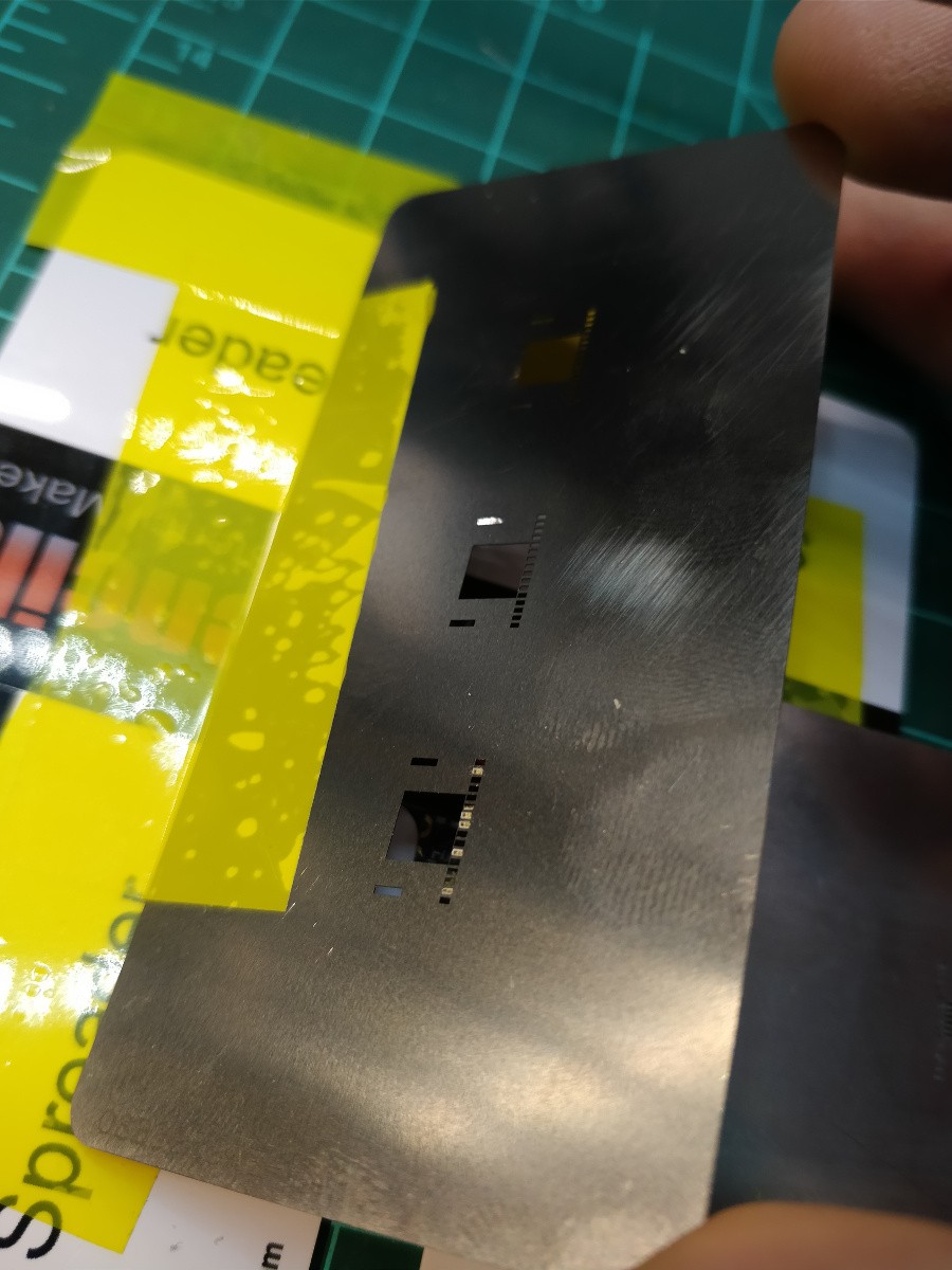
![]()
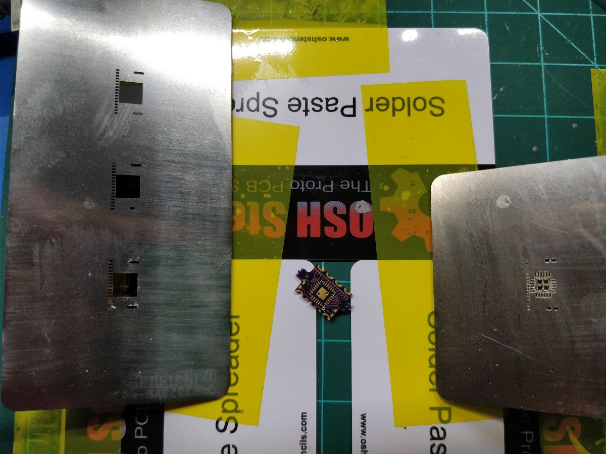
[above, a Rotovis-Mod1 board with a solder paste stenicl on the right and an alignment stencil on the left. They're both carefully taped down so one can be flipped onto the PCB after the other. I think the reason OSHstencils doesn't sell 1/32" alignment jigs is that their paste spreaders are the right thickness for that size PCB. And yes, the actual board gets its mousebites carefully sanded off before assembly...]
I wanted a better method for actually applying the 0201 LEDs to the PCB after paste. I sent a paste Gerber to OSHstencils that fit the outline of each component: extra clearance for the passives and IC, and three different sizes for the LEDs -- nominal (0.65mm x 0.35mm), +0.03mm per dimension, and +0.06mm per dimension. The largest one fit best:
![]()
[above, inserting the 14th of 16 LEDs onto a pasted Rotovis-Mod1 board through the alignment stencil. Breadboard jumper for scale... ]
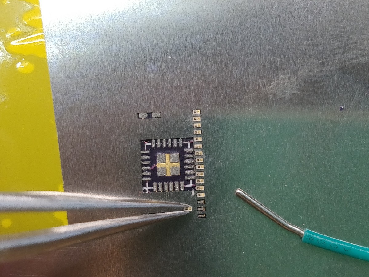
...but the stencil fit was still a little bit tight on a few LEDs:
![]()
[GAH NO NO NO NO NO NO THIS IS HORRIBLE]
The issue above -- LEDs sticking in the alignment stencil -- was actually pretty easy to fix; I just lifted the stencil a tiny bit and used tweezers to poke through any LEDs that held on. This worked well and helped me avoid rework on a few (but certainly not all) of the boards. Going 16 for 16 often resulted in a shout of joy, which is one reason I'm doing this on a weekend.
I don't take good care of my SAC305 solder paste; it sits in a syringe on my workbench until I need it, as opposed to being kept in a food-free refrigerator and tossed after 6 months. So I also started mixing a bit of gel flux in with the solder paste so it was a bit more sticky -- maybe 20% flux by volume. This made the QFN paste print look pretty rough, but helped the LEDs stick to the board and survive a trip through the toaster oven. Which, as I've said before, isn't special -- it's just a stock convection toaster oven that I run on preheat mode for ~4 minutes at 205 C.
Rework wasn't pleasant. Lots of hot air and cursing, but I managed to avoid scrapping any boards. Okay, I scrapped one board. And probably two dozen LEDs. Ah well, that's why I bought a ton.
-
inspiration & history
10/31/2017 at 15:32 • 0 commentsPersistence-of-vision displays are fascinating. They can create text and images out of thin air, and the hardware can be quite small compared to the size of the display if user-generated motion is used to create the 'scan' dimension. I think POV displays never took off commercially (with a few notable but small exceptions) for a few main reasons: it's tough to make a rectilinear display; high-speed mechanical display scanning is loud, power-hungry, and somewhat dangerous; and blue LEDs weren't viable until well into the age of LCDs.
The first part of this log will cover a few POV projects and products that I feel are interesting; if you think of any others, feel free to add a comment below. The second part discusses two of my projects that evolved into the Rotovis-Mod1.
inspiration
Virtual Boy
![]()
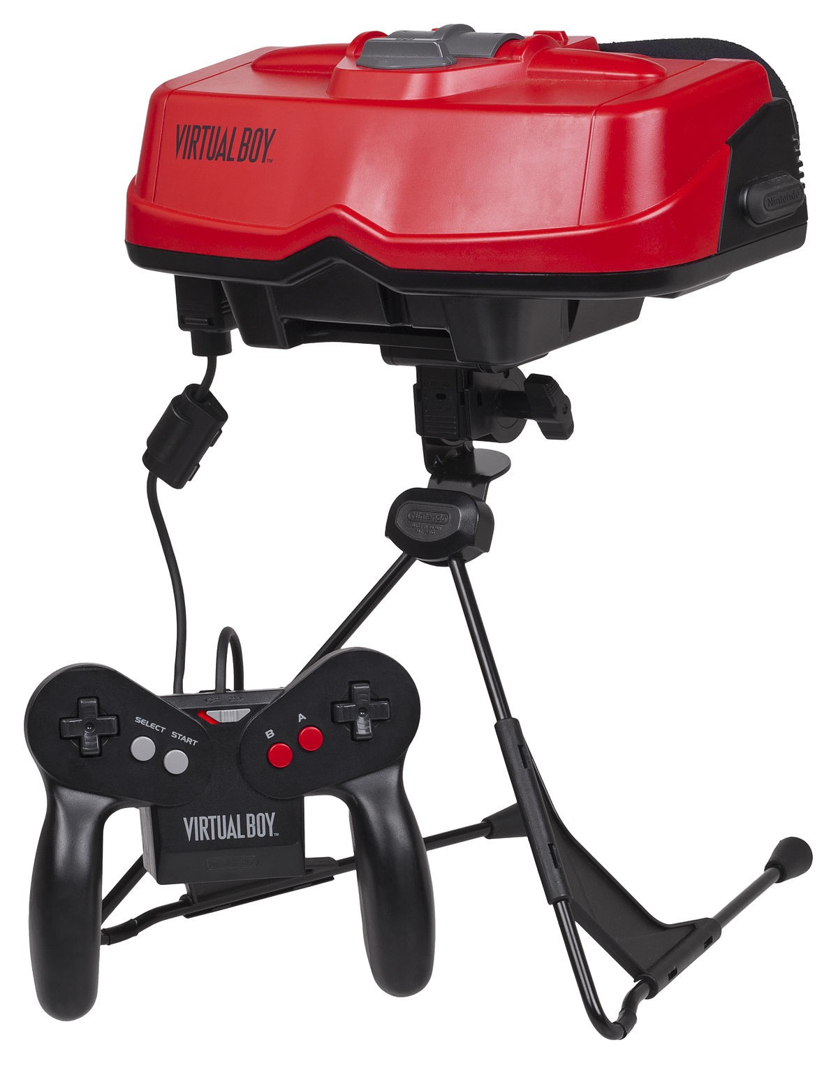
[Virtual Boy system. Photo by Evan-Amos, available here.]
The Virtual Boy is a game system developed by Nintendo in the early 90s. It's a fascinating system for many reasons, including the unique form factor (the device sits on a table during use) and the unique true-3D games. However, the display technology is the key for this project.
![]()
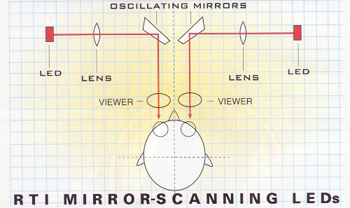
[Virtual Boy display diagram. The mirrors rapidly scan back and forth, turning the linear LED arrays into a full image. Photo from Micro-64, available here.]
As shown in the diagram above, the Virtual Boy used a pair of 224-pixel red LED arrays that were rapidly scanned using two oscillating mirrors to create two 384x224 images. The LED arrays, which are occasionally available on eBay as replacements for broken VB units, were designed by a company called Reflection Technology Inc.
![]()
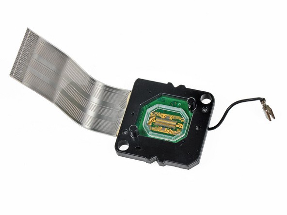
[Virtual Boy display module, showing the tiny 224-element LED strip. Photo from iFixit's excellent and thoroughly documented teardown of the game system, available here.]
As far as I have been able to tell, the RTI display modules are by far the highest resolution POV-specific LED arrays ever created, and I don't believe they were ever used for any other products. I wish the modules were more readily available, as I would feel bad using eBay'd displays and potentially depriving a Virtual Boy fan of the parts need to fix their broken game system.
SpokePOV
![]()
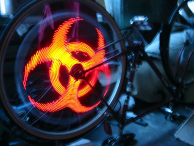
[SpokePOV installed on a bike, showing the biohazard symbol. Photo by Limor Fried, available here.]
The SpokePOV, from what I can tell, was one of Adafruit's first products. The kit used an array of 30 LEDs and a bundle of shift registers to create images, and is driven by an ATtiny2313 microcontroller. Combined with a Hall Effect sensor and a rare earth magnet mounted to a bike frame, the SpokePOV would display simple graphics on a user's bike wheel.
![]()
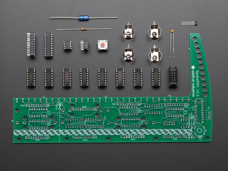
[SpokePOV kit, no longer for sale but info still available here.]
I became aware of the kit when I started buying USBtinyISP programmers; that product is also called the 'USB SpokePOV Dongle', as it was originally intended for use programming SpokePOV boards. The SpokePOV is quite low resolution, but for its use case (bike safety + teaching basic soldering) it was a great product; viewed from ten meters away, the images were crisp enough and quite bright.
voLumen
![]()
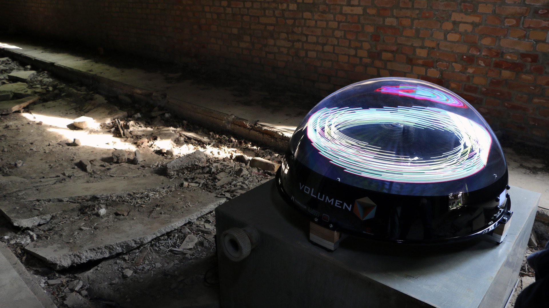
[voLumen gallery image, available on the project page here.]
Currently, there are 28 projects on Hackaday.io that include the 'Persistence of Vision' tag. #voLumen isn't one of them (it's under 'POV' instead), but it was one of the first I saw when I joined the site and still stands out as one of the most polished examples around. As suggested by its name, voLumen uses a number of stacked POV display 'leaves' to create a 3D display, and @max.mali did a great job integrating the whole system into a nice case. The project page doesn't offer a ton of behind-the-scenes detail, but from what I can tell the system uses 1024 RGB LEDs on 34 spinning vanes to create the images.
Astral Hoops
![]()
[Astral Hoops POV hula-hoop in action. Image from the product site, available here.]
Astral Hoops builds and sells LED-based performance accessories -- wands, staves, and hoops -- that use RGB POV elements to display graphics. I haven't seen their products in real life, but my guess is they have put a great deal of thought into real-world durability since the products are designed to be swung around at late-night outdoor events. They also have a neat computer program that allows users to create their own custom graphics. As with the SpokePOV, these systems trade resolution for brightness and long-range visibility; one of the pages suggests LED spacing of 0.66", so I'm guessing they use DotStar pixel strips or something similar.
SC15 POV badge
![]()
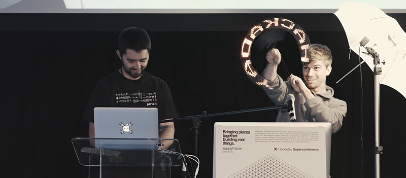
[Hackaday Superconference 2015 Badge Hacking show-and-tell. Image from article.]
The first Superconference produced some excellent badge hacks; my personal favorite was the 10-LED + Teensy POV badge. It worked so well with the lanyard! Person who made this badge, please remind us all of your name so credit can be given!
history
blinktronicator: ~13 DPI
![]()
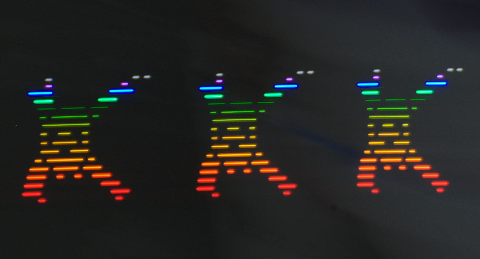
[#blinktronicator in Mode 3, getting swung around to display the HaD logo. The skull is roughly 0.8" tall.]
blinktronicator was a project designed to help me choose LED colors properly; the POV mode was more of an afterthought, but ended up getting me interested in the topic. Of note in the image above -- the skull distortion is due to the curvature of the display, not some funky camera issue.
![]()
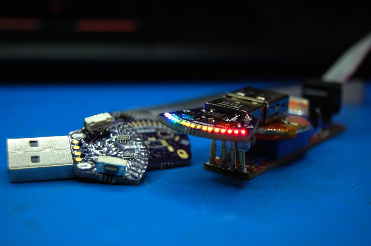
[blinktronicator, sitting on its sketchy programmer with all LEDs illuminated.]
In terms of persistence-of-vision projects, blinktronicator taught me that (a) high data rates are important (the bit-banged control from its ATtiny45 couldn't do much), and (b) higher resolution and closer spaced LEDs look better.
twisty watch: 32 DPI
![]()
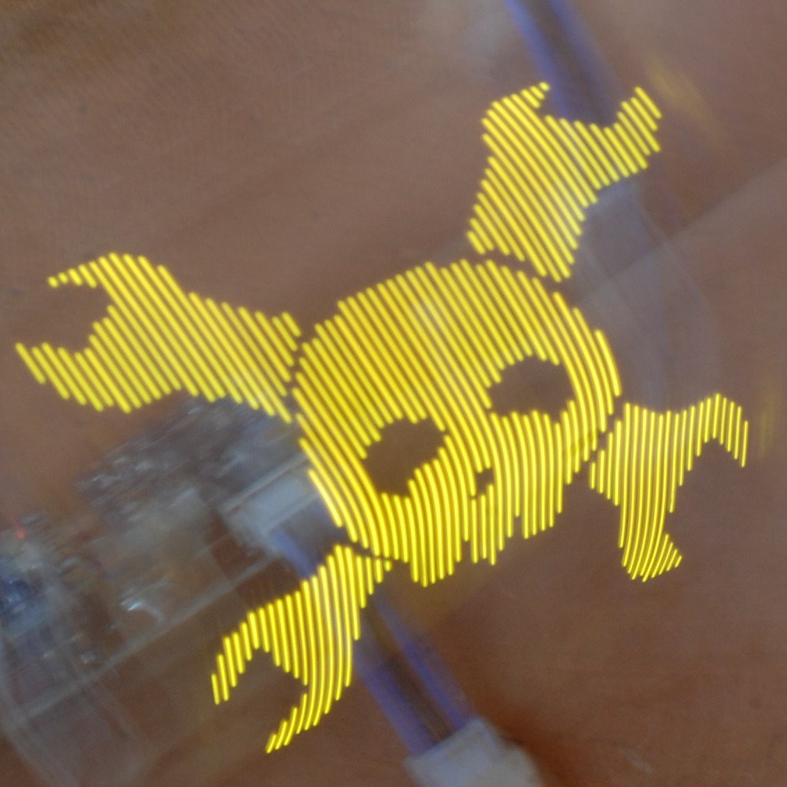
[Twisty Watch showing, as usual, the Hackaday logo. Image from project log. The skull is roughly 2" tall.]
Twisty Watch was a rapid-fire effort to build a high-res POV display and integrate it into a wearable device. The latter didn't work out very well; the controller PCB had some issues so I spun up a last-minute Teensy bodge so I could bring the project to OSHpark's open house at OHS16. But the display board itself worked well enough. It used sixty four 0402 LEDs with individual current limiting resistors and eight HC595 shift registers.
![]()
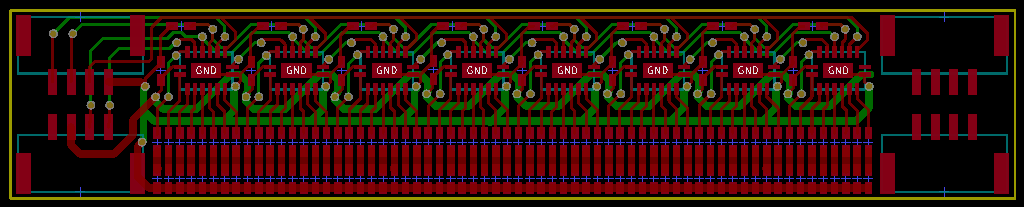
[Twisty Watch display PCB layout.]
In addition to some lessons learned about wearables -- comfort and sweat are things that must be dealt with -- the display itself carried its own learnings as well:
- I crammed as many PicoLEDs into the display as possible, pushing a tiny bit past Rohm's datasheet recommendation on minimum LED spacing. This made soldering a massive pain, as slight misalignment caused multiple LEDs to buckle during reflow resulting in hours of rework. Since each board contained the entire display, screwing up the rework process and scrapping the module (and a ton of LEDs) was a serious risk.
- Rotovis-Mod1 reduces the rework/scrap risk a bit by breaking the display into single-chip modules; while they are each substantially harder to solder or rework compared to the Twisty Watch display, individual screw-ups carry a smaller penalty. Switching to 0201 LEDs also allowed me to improve resolution by 25% while not pushing the spacing limit to an extreme; while the tiny elements are pretty dang close together, there is enough air space between them to avoid buckling or other inter-pixel interference during soldering.
- Using individual current limiting resistors wasted energy and took up a ton of space (relatively speaking). Ditching these for a current-limiting source would save real estate and make the whole design much cleaner.
- The TI chip using in Rotovis-Mod1 -- essentially a 16-bit shift register with constant current drivers on the back end -- solved this problem quite nicely.
- The Twisty Watch wasn't designed with expandability in mind; the four connectors meant multiple boards couldn't be daisy-chained into a single display.
- Yay modularity! This would have been easy enough on the Twisty Wrist board (simply lopping off the JST GH connectors on either side), but it was important to keep this goal in mind from the start when designing the new PCB.
- Still .. must .. improve .. resolution .. 32 DPI was impressive but I wanted to improve this number as much as practically possible.
- I know I'm doing a project right when today-soldering-me hates last-week-PCB-designing-me.
angstroleds: 64 DPI
UPDATE 11/9: I forgot about this one when I put the log up originally! So .. to be fair .. the 'lessons learned' above partially share history with angstroleds, since it definitely made some of the same mistakes as Twisty Watch:
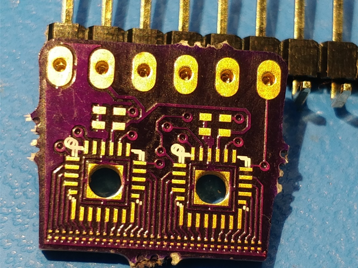
![]()
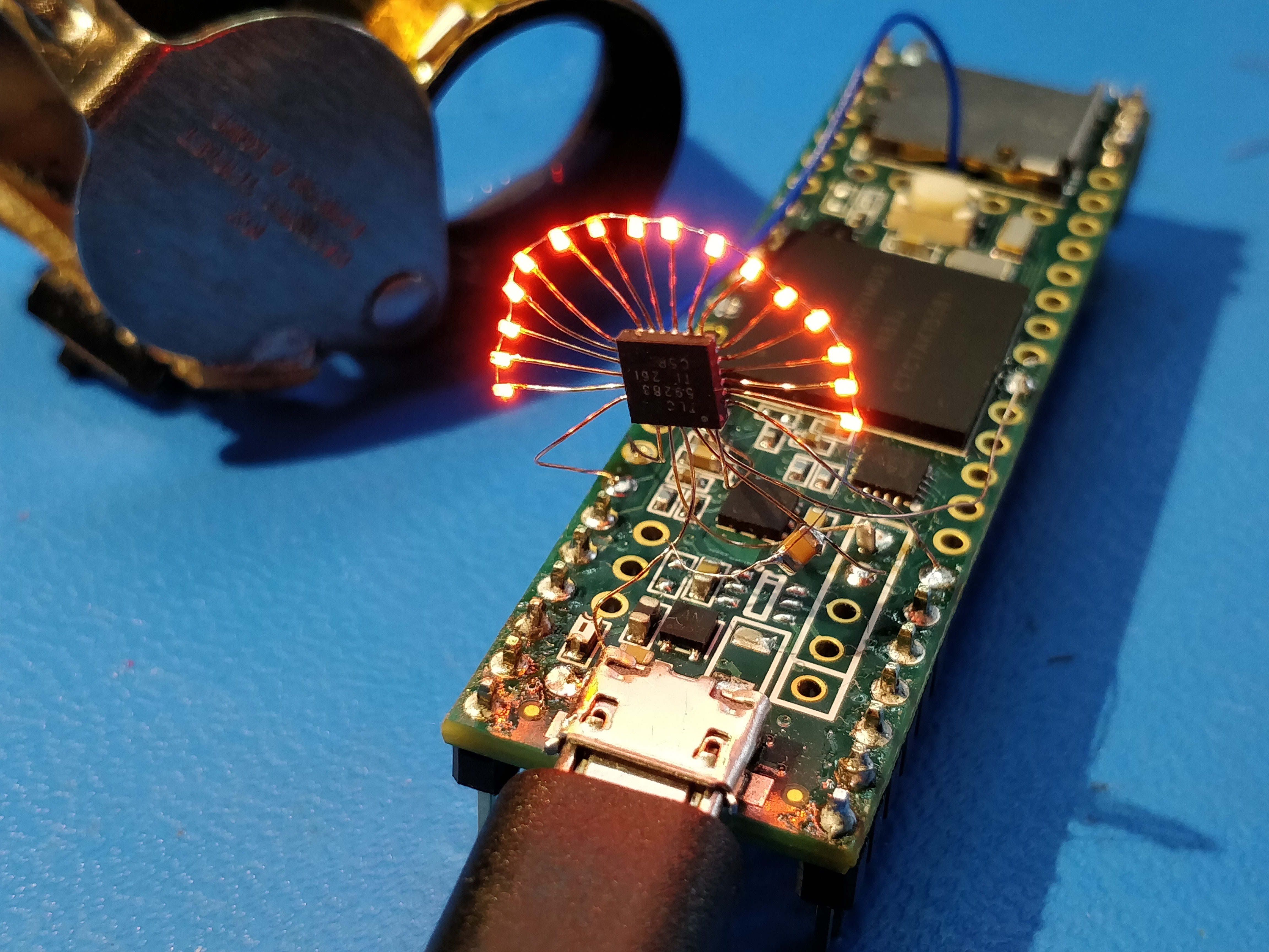
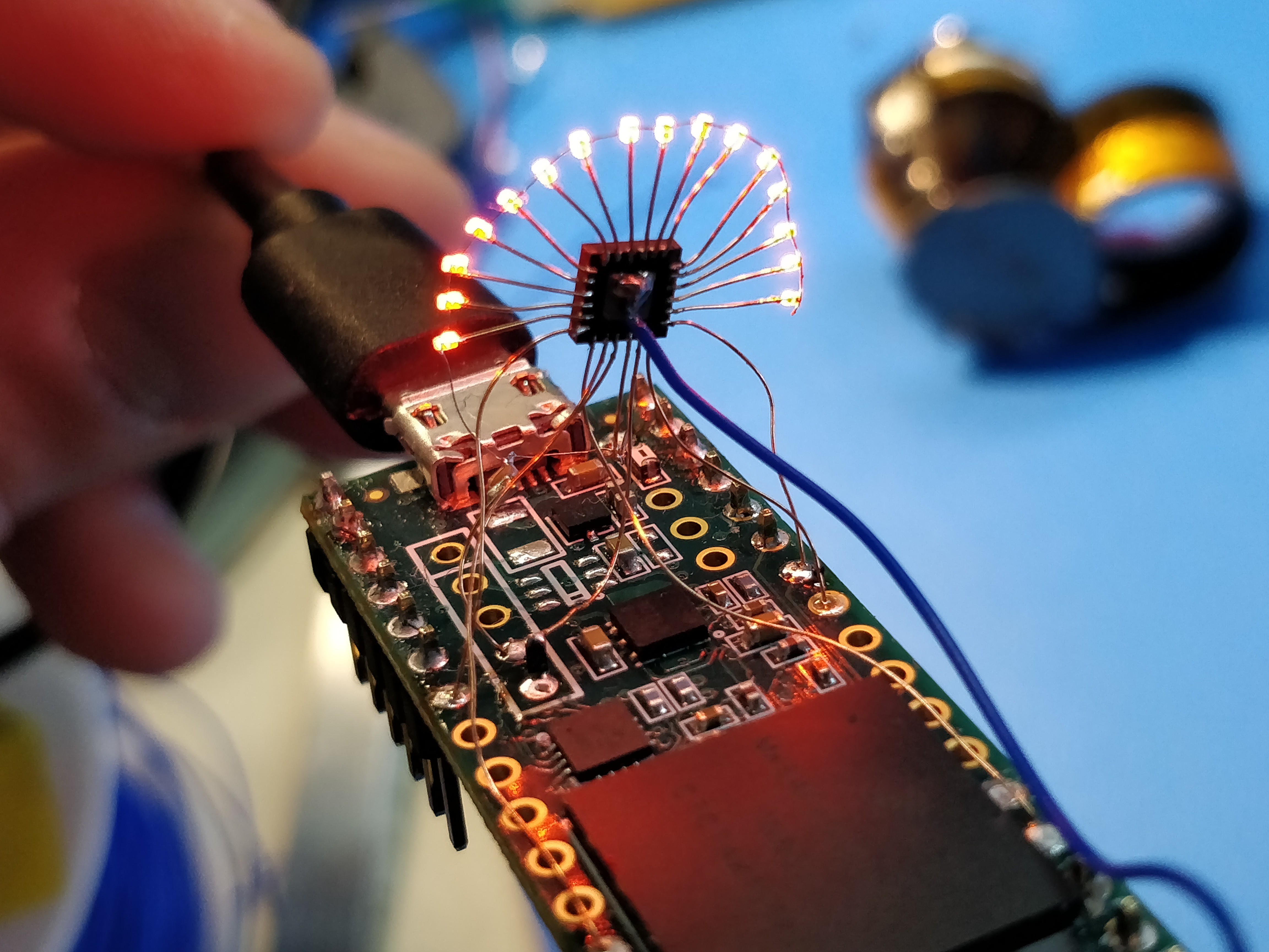
... namely, trying to bunch the LEDs waaaaaaay too close together. While I imagine Rotovis-Mod1 could be _somewhat_ improved (maybe to 48 DPI?), the project really ends up being limited by the TI chip size; you can see in the images above that I ended up seriously bodging the footprint, even rotating some outward-facing legs so they were parallel to the LED display. I also included big plated through holes so I could hand-solder the whole thing.
Needless to say, the insane LED spacing (along with those two idiotic rotated pins) meant angstroleds never saw the light of day, even with a reflowed LED controller. To add insult to injury, I made the header holes too small. Gah!
- I crammed as many PicoLEDs into the display as possible, pushing a tiny bit past Rohm's datasheet recommendation on minimum LED spacing. This made soldering a massive pain, as slight misalignment caused multiple LEDs to buckle during reflow resulting in hours of rework. Since each board contained the entire display, screwing up the rework process and scrapping the module (and a ton of LEDs) was a serious risk.
Rotovis-Mod1
40-DPI monochrome LED module designed for persistence-of-vision displays. 16-element bargraph in an 8-pin castellated DIP package.
