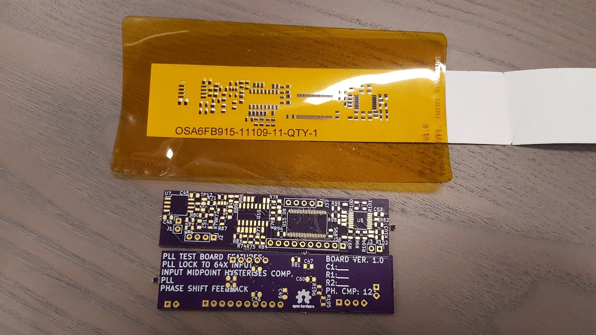
Prototype board and top solder stencil for PLL. The design goals are
support ~1Hz - 100kHz input frequency
"arbitrary" waveform that is between +-5V and crosses its midpoint twice per cycle.
outputs 64x the input frequency for the ADA2200 demodulator
phase shifts output to allow manual phase adjustment.
I'll be populating and testing this out in the next few days. I may decide to OBE the phase shifter in favor of just having 2x ADA2200, and support I and Q demodulation and digital phase shifting.
 JasMoH
Discussions
Become a Hackaday.io Member
Create an account to leave a comment. Already have an account? Log In.