Close
0%
0%

Bicycle Regenerative Braking System

Turn excess kinetic energy into electrical energy rather than waste all it as heat. Built from commonly available and recycled parts.

Similar projects worth following
Mountain bike riding through the Australian bush can be an enjoyable sport, especially when camping overnight. But when camping for several nights away from civilization, a major problem arises; how to keep all the GPS, phone, laptop, camera and flashlight batteries charged?

When riding down a steep hill or coming to a stop, energy is being wasted into the disk-breaks (or caliper breaks) as heat, so why not instead harvest that energy and use it to charge the batteries for those devices? Bicycle dynamos do exist, but generally do not output more than several watts maximum; not nearly enough to function as a brake.

The Bicycle Regenerative Braking System (BRBS) will instead use a more powerful dynamo loaded with a variable-impedance switchmode converter, controlled via the bike's front brake lever. The BRBS will also display the load-impedance, output power and efficiency as well as the bike's instantaneous speed and acceleration.

The BRBS will charge 16 individual 18650 Li-ion cells (yes there's 17 slots but one will be empty) with a common negative. Electronic devices to be brought along will accept 18650 cells or will be modified to do so. In the case of cameras, a swichmode camera battery charger will be built as there's not enough room in a camera for a 18650 cell.

Future ideas:

1. Use a brushless motor (Hobbyking 2KW outrunner or something like that) to reduce friction.

2. Allow the dynamo to run as a motor to help getting up the steeper hills (some torque on the front wheel would really make things easier). Of course it would have to be used sparingly.

3. Following on from the above, maybe even a winch attachment for hills that are more that 45° steep...

  • 1 × Cordless-drill motor/gear-box from a Ryobi drill with a 13mm chuck. It had been driven over and the handle was snapped off
  • 16 × 18650 Li-ion cells from laptop-batteries
  • 1 × Adjustable lever with short wire brake-cable Used to change gears on the dynamo. It can be set to a position and will stay there.
  • 1 × A spring as the wire brake-cable can only pull
  • 6 × Pipe clamps Someone's car is going to have overheating problems...

View all 10 components

  • Finishing up

    recyclojunk01/23/2015 at 14:56 0 comments

    (I had written this up earlier but somehow forgot to post it! The actual camp happened on 140914)

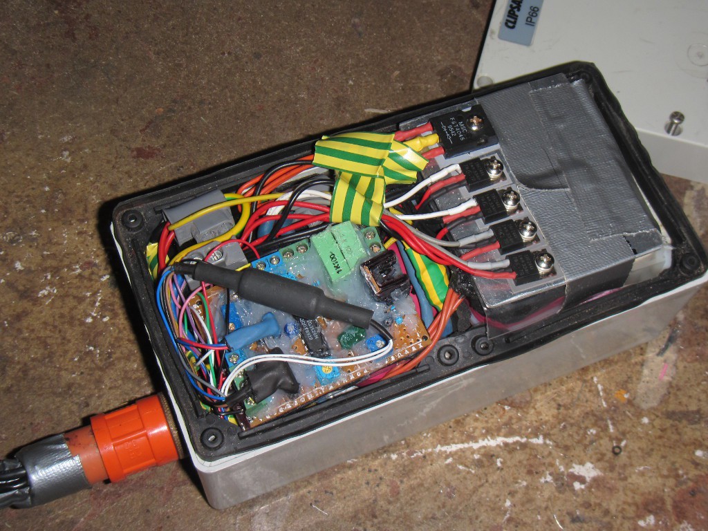
    Everything had to fit into a Clipsal weatherproof electrical box. The two capacitor banks were sized and shaped to make the most of available room. There was only room enough for one LC filter, which I placed on the output (as a boost-converter's input current is relatively smooth even without any filtering). Soon everything was fitted in and I gave it a test. It didn't work anymore. After alot of probing around (a long BNC cable comes in handy when riding the bike while tethered to the o-scope) the MAX44284 current-sense amplifier was found to be fried. I ensured it's 5V supply (78L05 regulator) was as normal and replaced the amplifier, only to find that the replacement was also fried. Must have been an electrostatic-discharge on it's sense pins; this isn't the first time I've had Maxim parts die for seemingly no reason. So it was replaced with a LTS25-NP hall current sensor (hacked to also output it's 2.5V reference, which it's output was amplified against by a 4x gain differential amplifier). And it finally worked again!

    (yes the wire colours on the mosfet pins are mixed up. Also, they're all in parallel (yeah, overkill alright))


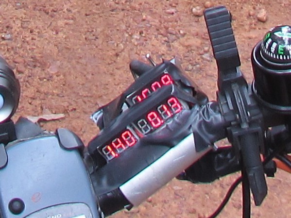
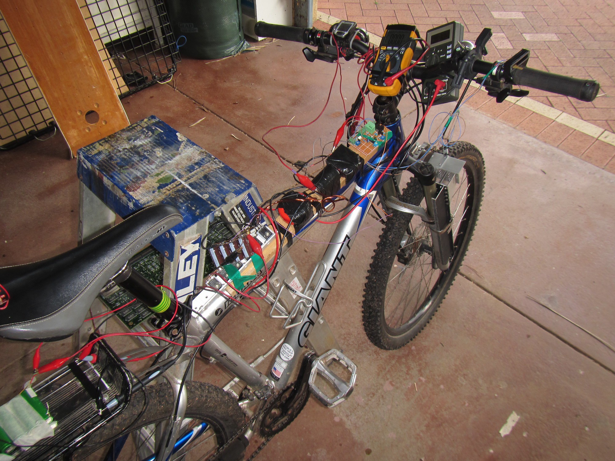
    It was now Saturday and the trip was scheduled for Sunday, and I hadn't even started packing. As the forcast for the week was mostly sunny, there was no need for it to be waterproof just yet so I glued three voltage-displays to a piece of aluminium that I had attached to the handlebars, to display the input voltage and current, and the battery voltage. The controller was also modified to only power up the BRBS when the dynamo was spinning.

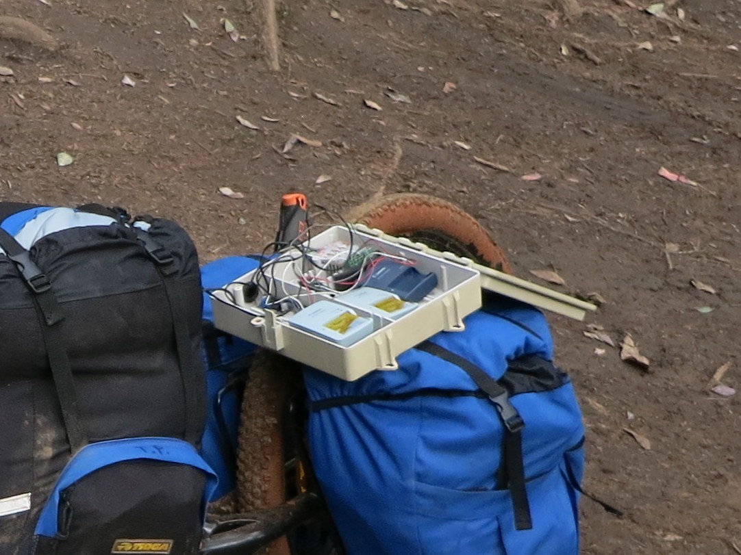
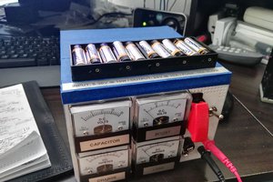
    (Not many pictures were taken in the mad rush to get it done at 0300 sunday morning, hence the picture from the camp)


    Now the BRBS itself was complete, but it still had to charge my camera batteries. I hacked together a quick charging rig built out of some 0.5mm pin-pitch TQFN Li-ion charging chips and a 5V switching pre-regulator I got off ebay, and put it in a nifty little project box I found screwed to a brick wall outside.


    Last step was to connect two more of those cheap switching regulators, one for the LED torch and one for the GPS. It was now early Sunday morning, so it was time to start organising what food and camping gear I was going to bring.

    Stay tuned for a writeup of the actual camp itself, and whether the BRBS a success or failure

  • The Control System

    recyclojunk09/28/2014 at 07:09 0 comments

    Due to some unfortunate circumstances, the guy I was going to complete the trip with had to be back by September 22nd (which was the original leave-date) so the 6-week trip had to be postponed and replaced with a 1-week trip. This also meant that I had 1 week less to complete the BRBS (though I didn't have to complete it as 1 week's worth of batteries probably weighs less than the BRBS anyway).

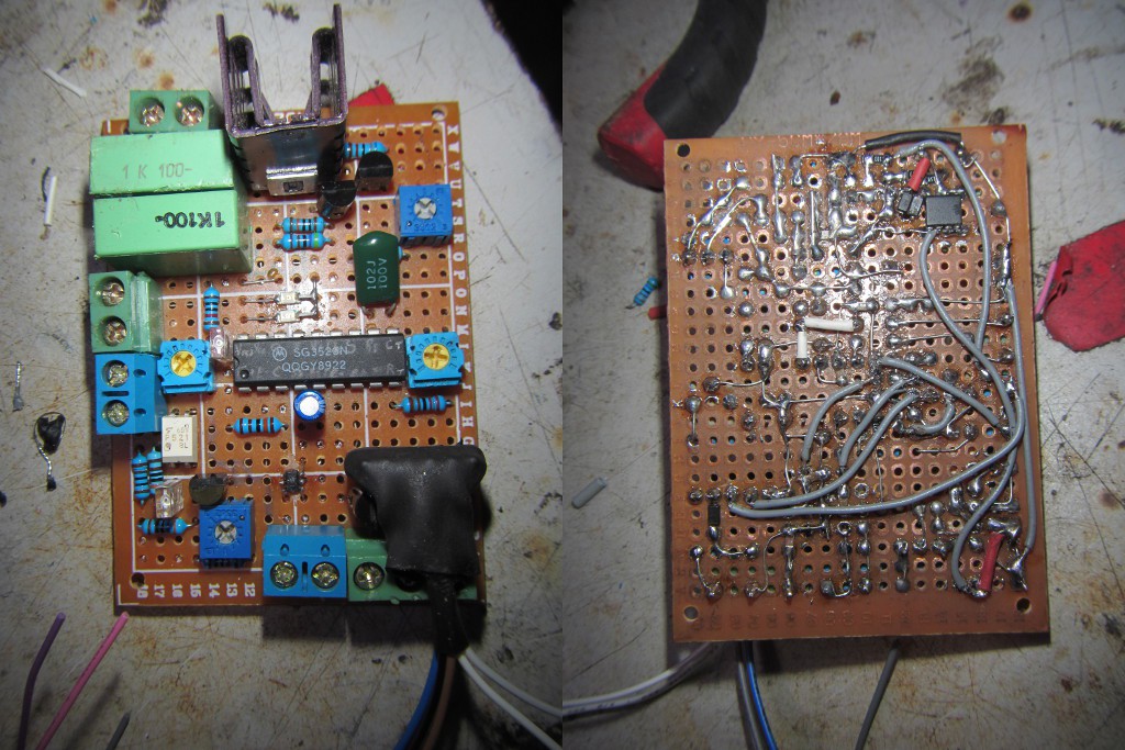
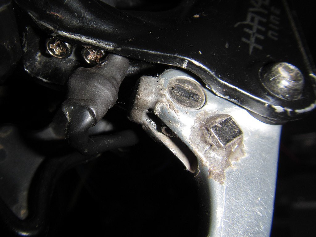
    The control system: I decided to use the same controller board I had built earlier. The controller has two totem-pole outputs each offset by 180°. As each one only goes up to about 49%, I used two parallel mosfets with a gate on each output. Next I had to devise a system of controlling it. A magnet and hall-sensor on the brake lever seemed most reasonable. I drained out a few drops of brake fluid from the brakes to create a larger 'dead-zone' for the BRBS to activate in. The problem however was what is to be controlled? Simply adjusting the duty-cycle of the boost converter will only adjust the input-to-output voltage ratio, meaning that the only thing limiting the output current would be internal resistance of the dynamo and the battery pack (ie. the brake will be either fully-on or fully-off, with very little control in-between). What it needed for a realistic braking experience was to simulate a variable output-impedance.

    (the other magnet on top was for an alternative mounting position of the hall sensor)

    Creating a variable impedance load isn't as easy as it may sound. The ratio of input current to input voltage needs to be measured, and then compared against a variable value (the inverse of the load impedance). There wasn't enough time to muck around with a microcontroller; it needed to be done in analog.

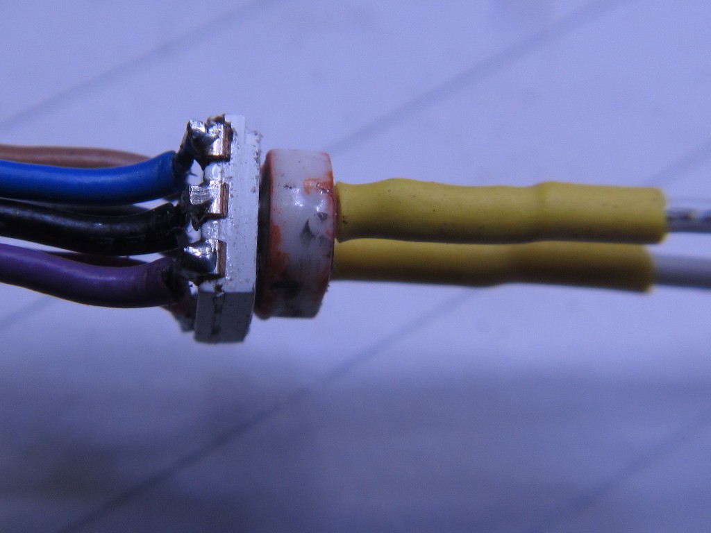
    The input voltage was attenuated by a voltage-controlled resistor (controlled by the brake lever hall-sensor), then fed into the inverting side of the controller's error-amplifier. For the voltage-controlled resistor, an LED was glued to a CdS light-dependent resistor (according to standard procedure) and covered with more glue and heat-shrink tube. A variable resistor was placed in series to adjust the minimum load-impedance, so that it would never go below the impedance of the dynamo. A measurement of the input current was fed into the non-inverting side of the error-amplifier, taken with a MAX44284 high-side current-sense amplifier (quite overkill, I only had to use few cm of 18AWG wire as the current shunt because of the 200x gain). And it worked!

    (There's actually 3 LEDs there, for separate galvanicly-isolated inputs just in case I need them in a later modification)

  • Shortcuts With Battery Management

    recyclojunk09/01/2014 at 08:08 0 comments

    With less than two weeks until the planned date for the trip, I really have to hurry up and get this done, so I can start packing and organising the other stuff.

    So I've decided to take a shortcut. Instead of charging 16 removable batteries separately, I'm going to build a non-removable 15V pack (4x4 series-parallel). I'm not going to bother with balancing, but I'll ensure the cells are matched so there won't be as much need for balancing anyway. I will most likely implement the proper charging circuitry later on after this trip however (or if I get time before it).

    The new dynamo seems to put out a lot less voltage than the last one, even when in low gear. 1.1V and 0.34V per km/h for low and high gears respectively (with 0.3Ω internal resistance). So I might as well just use an ordinary boost converter for the charging. I'll run the controller directly from the battery so it will work even at very low speeds/input-voltages. 

    Ready for a quick test. Works well, but I'll have to modify the controller as currently the duty cycle won't go above 50% (Vout = Vin / (1 - Dcycle) )

    (I did briefly consider using a 12V 7Ah lead-acid battery in the last post but at 2kg and only 85Wh I'd be better off simply (ab)using some laptop batteries in an unbalanced pack.)

  • Mechanical Side Finished

    recyclojunk08/31/2014 at 06:10 0 comments

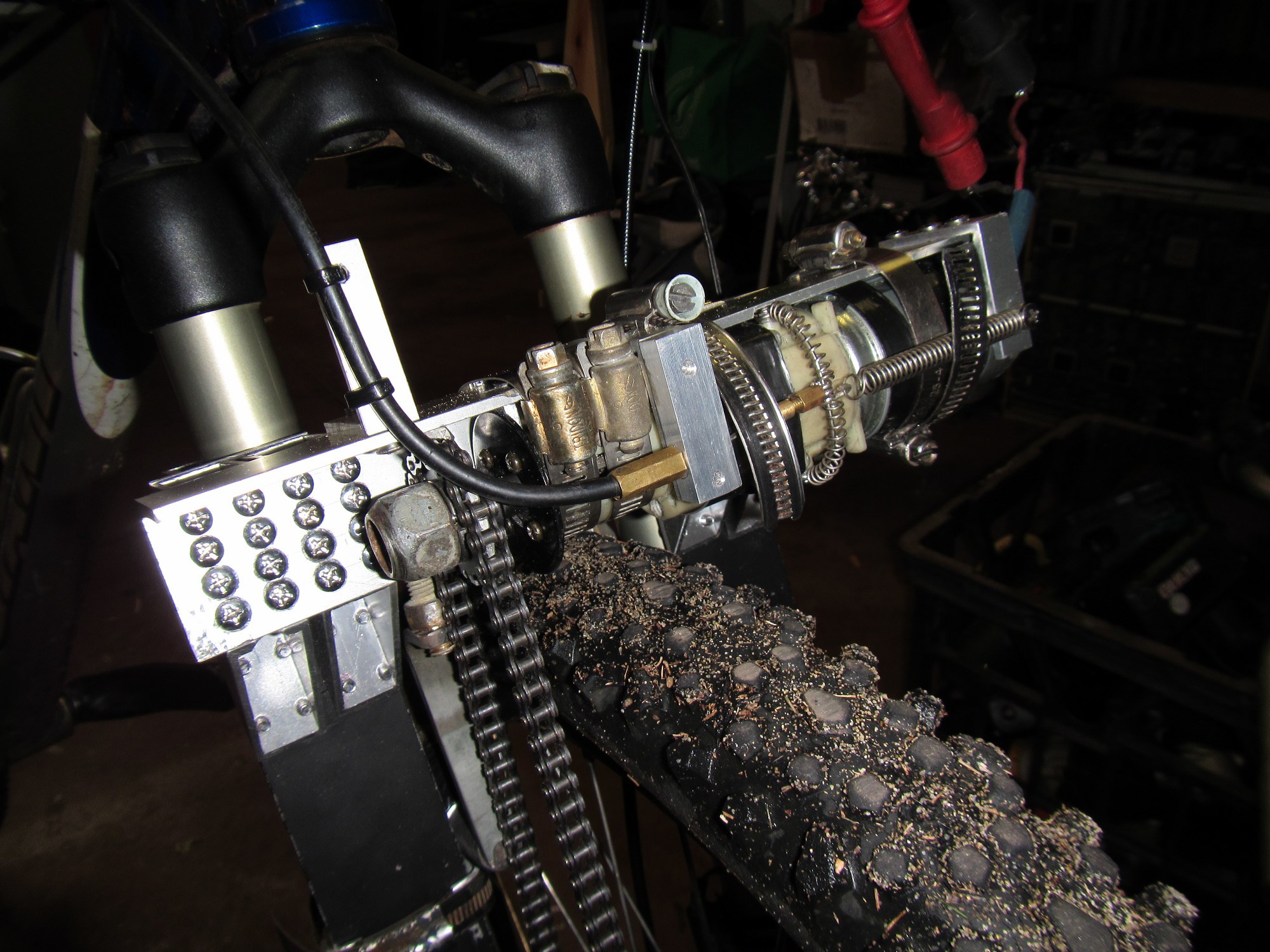
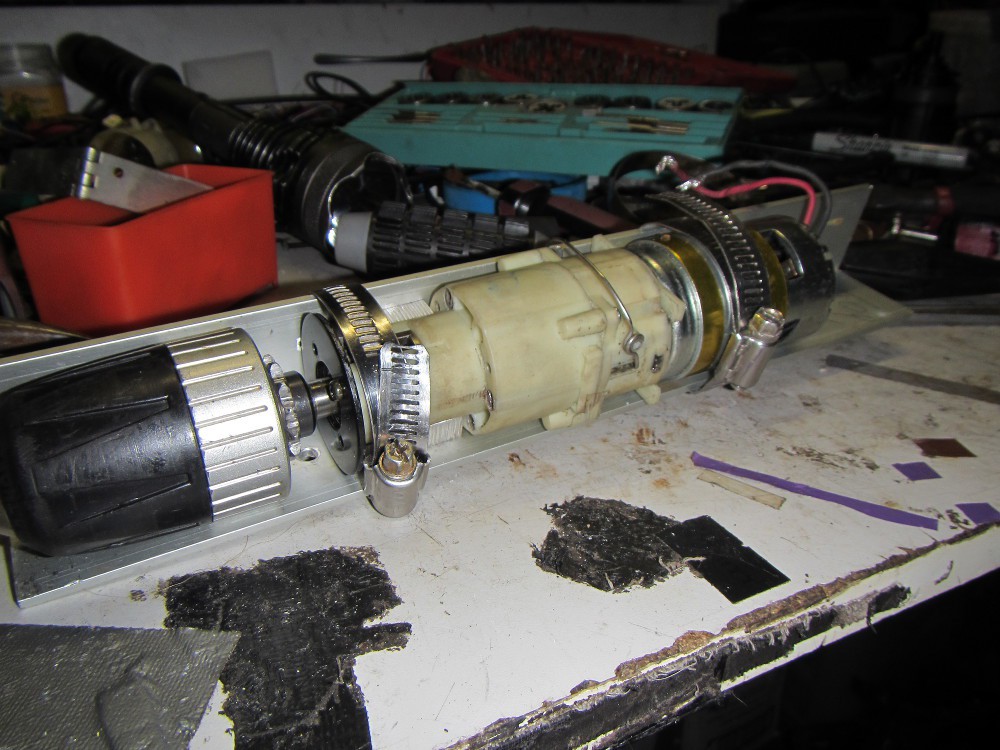
    Finally the mechanical stuff has been finished (or so I hope). The dynamo is now a cordless-drill motor/gear-box instead of the original motor from a printer. There is also a choice of high or low gearing, so I can use it on low when going down a hill and needing the braking power, and on high when riding normally and not wanting it causing too much drag and noise. It also has a neutral for when silence is needed.

    Now for the electronics. With only two weeks to go until the camp, I'm not completely sure I'll get all 16 of those switchmode converters done. And of course I also have to organise and pack everything else as well. So I am thinking of possibly cheating and just charging a 12V 7Ah lead-acid battery instead with a single buck/boost converter. The most power will be used by the cameras and laptop, which won't be any harder to run off of a 12v battery than 18650 cells. The only thing that really requires 18650 cells are the flashlights, which we will be using sparingly anyway.
  • Switchmode converter decision

    recyclojunk08/21/2014 at 06:38 0 comments

    There are two main choices of how to design the switchmode converter.

    1. A single switchmode buck converter that outputs 4.2V. This will then be fed to individual linear current limiters for each cell.

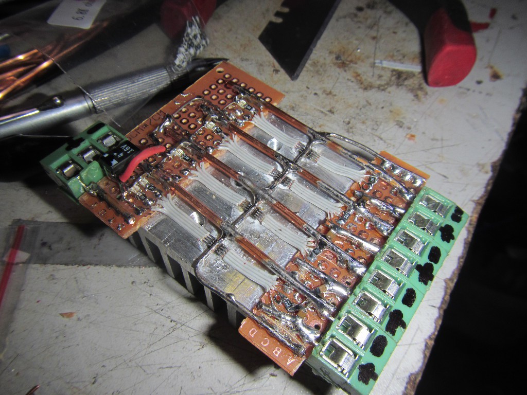
    2. A seperate swichmode converter for each battery. To make things simpler, I'll probaly use an intergated switchmode controller that only needs an external inductor and filter caps. Such as the MAX17504 (yes they're available as free samples) which has an input of 4.5 to 60V and has a synchronous rectifier.

    Originally I was going with option 1 but I've since changed to option 2 instead.

  • Change of Dynamo

    recyclojunk08/21/2014 at 06:33 0 comments

    After more testing with the new sprocket there seems to be a problem. When going down a steep hill at about 10km/h (typical speed) the load impedance has to match the generator's internal impedance in order to prevent the bike from going too fast. Meaning that half the outputted power is wasted in the generator's internal resistance.

    Using a smaller sprocket on the motor (causing it to generate more voltage per km/h) would reduce this problem, but cause significant drag when going at a speed greater than 20km/h even when there's no load.

    As I would like the option of generating power even when not braking, the ideal solution seems to be to have a two-speed gear system to couple the generator to the wheel. And where might a two-speed gear system and accompanying motor/generator be obtained? Why from a cordless drill of course!

  • Battery Holders

    recyclojunk08/21/2014 at 06:23 0 comments

    While it may seem trivial to make a battery holder, it turned out to be much harder than I thought. As I haven't finished my 3D printer yet, my options for building one were limited. And commercially available 18650 cell holders weren't going to cut it in the high-vibration environment of a mountain bike.

    First I tried making one out of MDF as a test, using a spade drill bit to drill out some 19mm holes for the cells. But I didn't have any material to build a proper one out of.

    Eventually I decided to make it out of electrical PVC conduit pieces glued together, with foam-supported battery terminals on the ends. There's 17 slots but one will be empty.

  • Machining a sprocket on a drillpress

    recyclojunk08/21/2014 at 06:17 1 comment

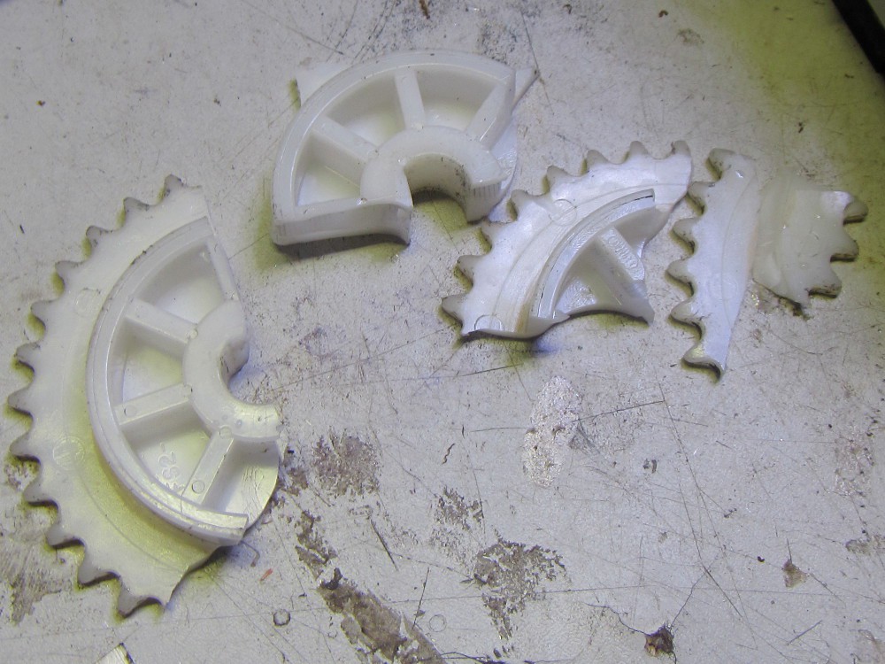
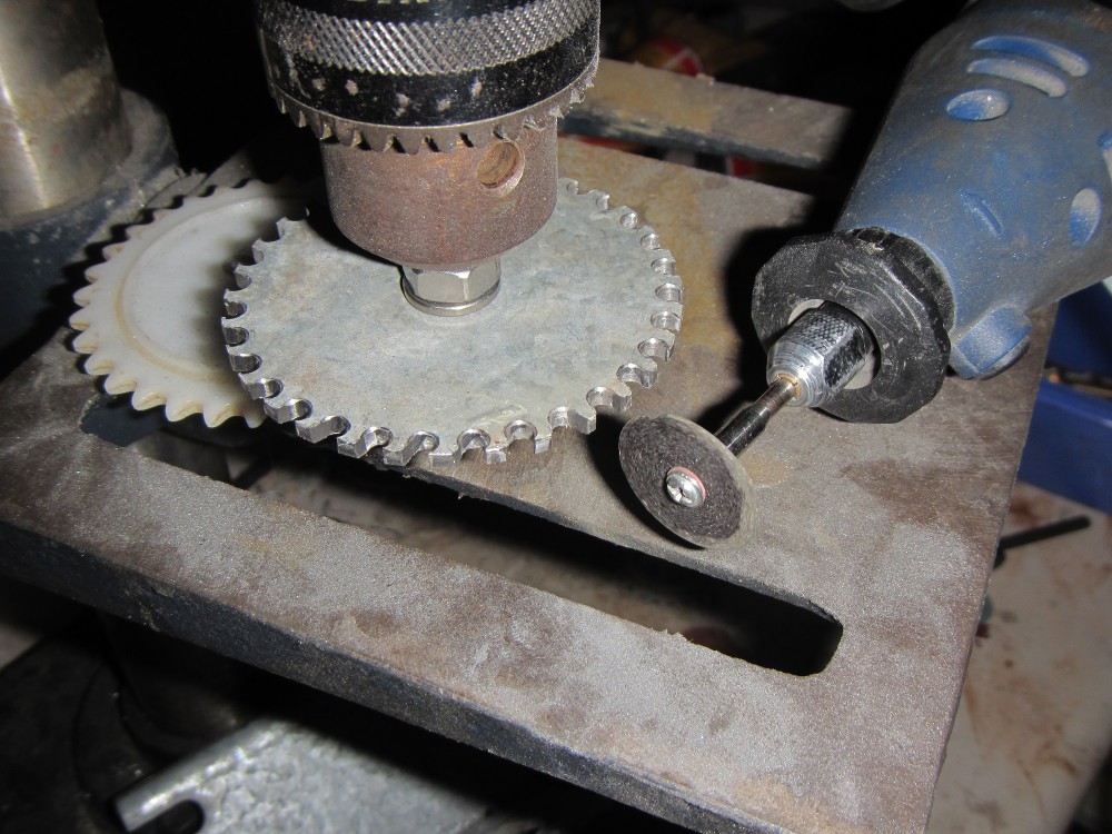
    Testing of the preliminary switchmode converter worked well, but after braking too hard while going too fast, the plastic sprocket shattered. Probably because the M4 screw bent, but I think it needs a metal sprocket instead. Unfortunantly the only metal sprocket for this type of chain I have is the one already on the bike's wheel, so I needed to drill one out on the drillpress and round it off with the dremel.

    After many hours of tedious drilling and grinding, the sprocket is finished. It works well.

View all 8 project logs

Enjoy this project?

Share

Discussions

recyclojunk wrote 08/22/2014 at 13:56 point
Seems like it's not possible to upload it to the same URL as the link I had when the HAD crew took the server snapshot, so I'm out of the comp. Anyway the writeup was thrown together in such a rush and the project isn't really "connected" in anyway so it wouldn't have made it to the next round anyway.

Such is the life of a procrastinator...

Speaking of which, I've gotta get this finished before my 6 week bike camp in September!

  Are you sure? yes | no

Greg Kennedy wrote 08/21/2014 at 16:02 point
Your video is missing : (

  Are you sure? yes | no

recyclojunk wrote 08/22/2014 at 02:11 point
Oh dear, I uploaded it in the last minute and it was saying "this video is being processed" but looks like that was unsuccessful. I'll have to try reuploading it in another format when I get home later, hopefully to the same URL or else I'm screwed!

  Are you sure? yes | no

Similar Projects

Does this project spark your interest?

Become a member to follow this project and never miss any updates