 Marius Taciuc
-
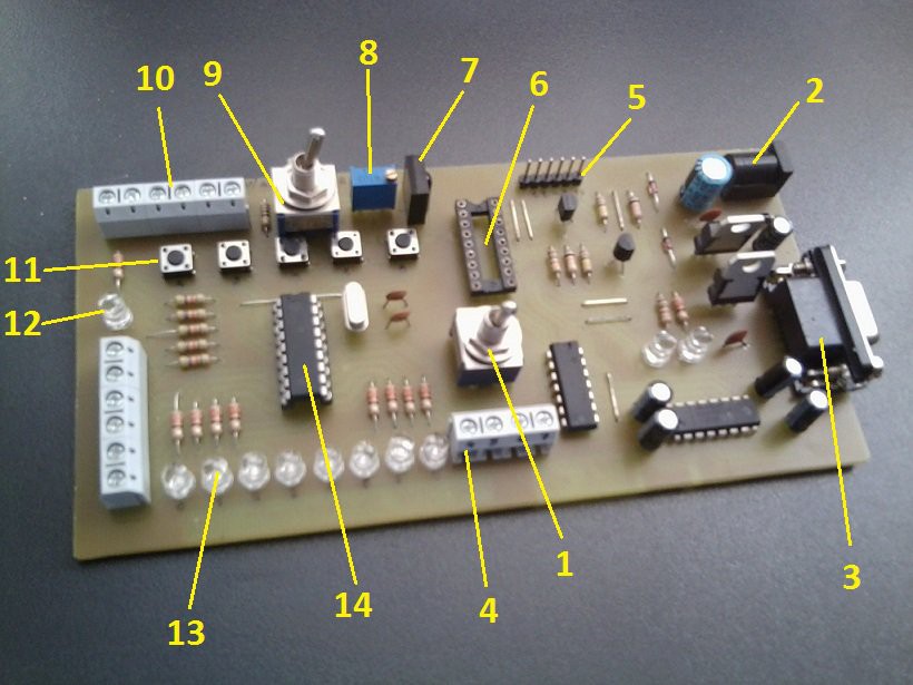
1Quick description
![]()
1. Power switch for the launchpad half
2. DC connector for the input voltage
3. RS232 connector for the JDM programmer
4. Output connectors for the PORTB pins
5. input connector for the PICkit programmer/ debugger
6. Programming socket
7. IR sensor
8. ADC input pot
9. I/O to ADC switch
10 PORTA pins busbar connector
11. PORTA switches
12. Power LED
13. PORTB LEDS
14. Launchpad socket
-
2Have fun blinking some LEDs
I also posted a couple of tutorials for the sake of old times explaining how to write a short ASM code and how to program it into a PIC16F628 MCU and blink some LEDs. Only for those who are interested:
-
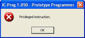
3IC-rog settings for using it as a JDM programmer
![]()
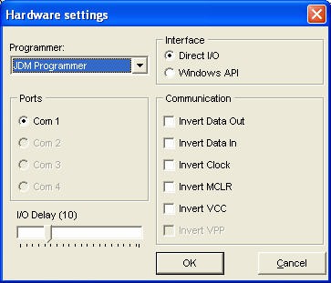
when the above message appears, go to the Hardware settings and select the following
![]()
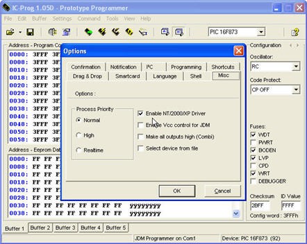
make sure to check the Enable NT/2000/XP driver tick box.
![]()
-
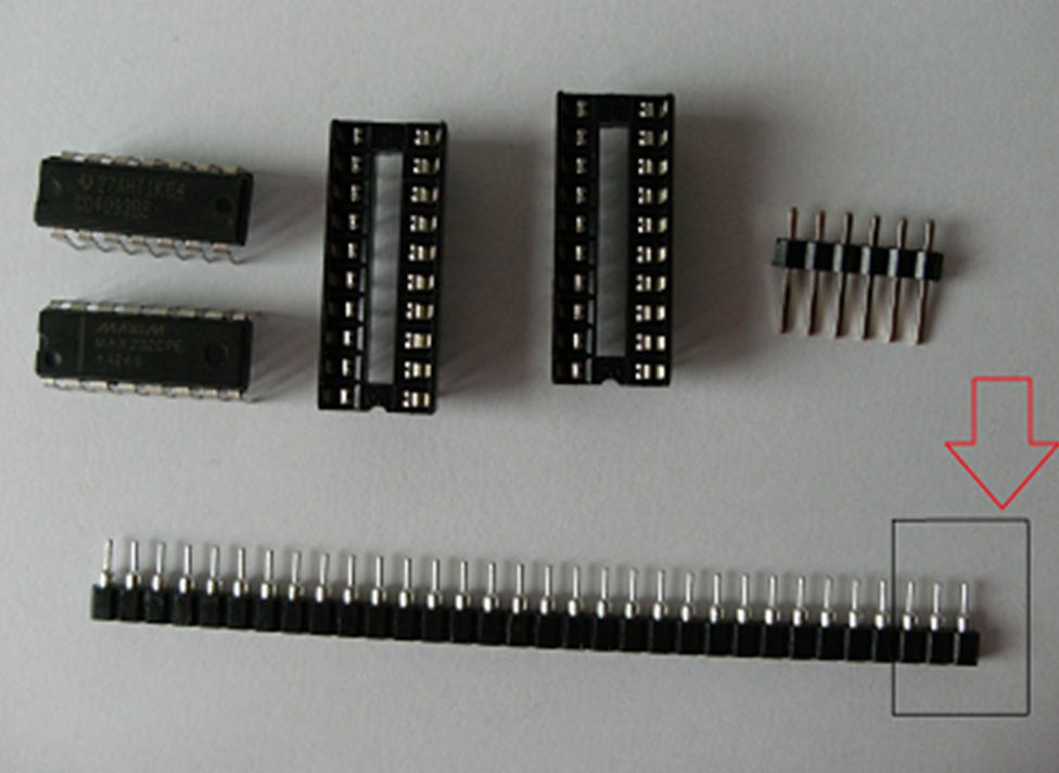
4Resonator socket
![]()
You can make a resonator socket like in the image above by trimming a line DIP socket and removing the center pin. This socket will allow you to switch between multiple resonators and configure your launchpad accordingly.
-
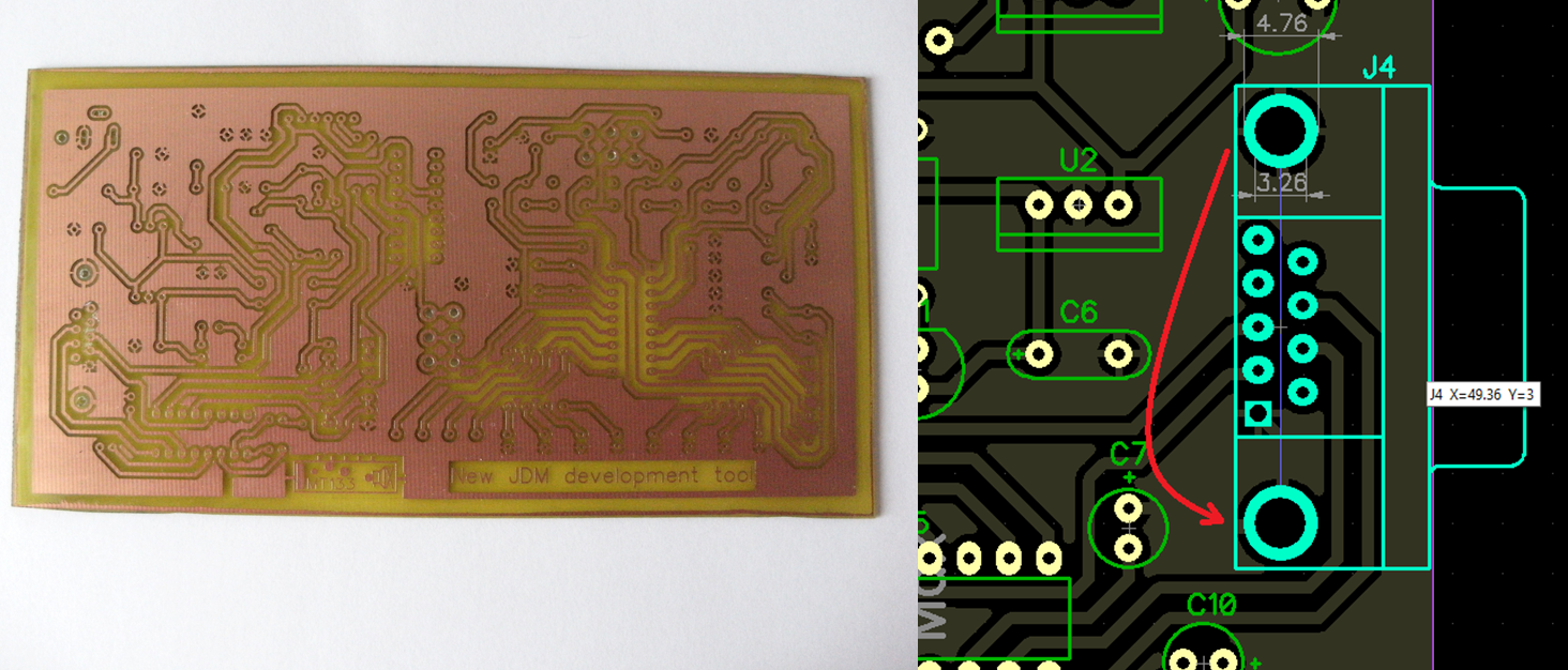
5About soldering the RS232 connector
![]()
Make sure you have strong connection between the mounting pads of your connector. If you don't have, make the above strap with a wire. This would provide the GND pin for the C7 capacitor.
Smart JDM launchpad
New JDM / PICkit development tool for interfacing just what you need
Discussions
Become a Hackaday.io Member
Create an account to leave a comment. Already have an account? Log In.