 Christoph Tack
-
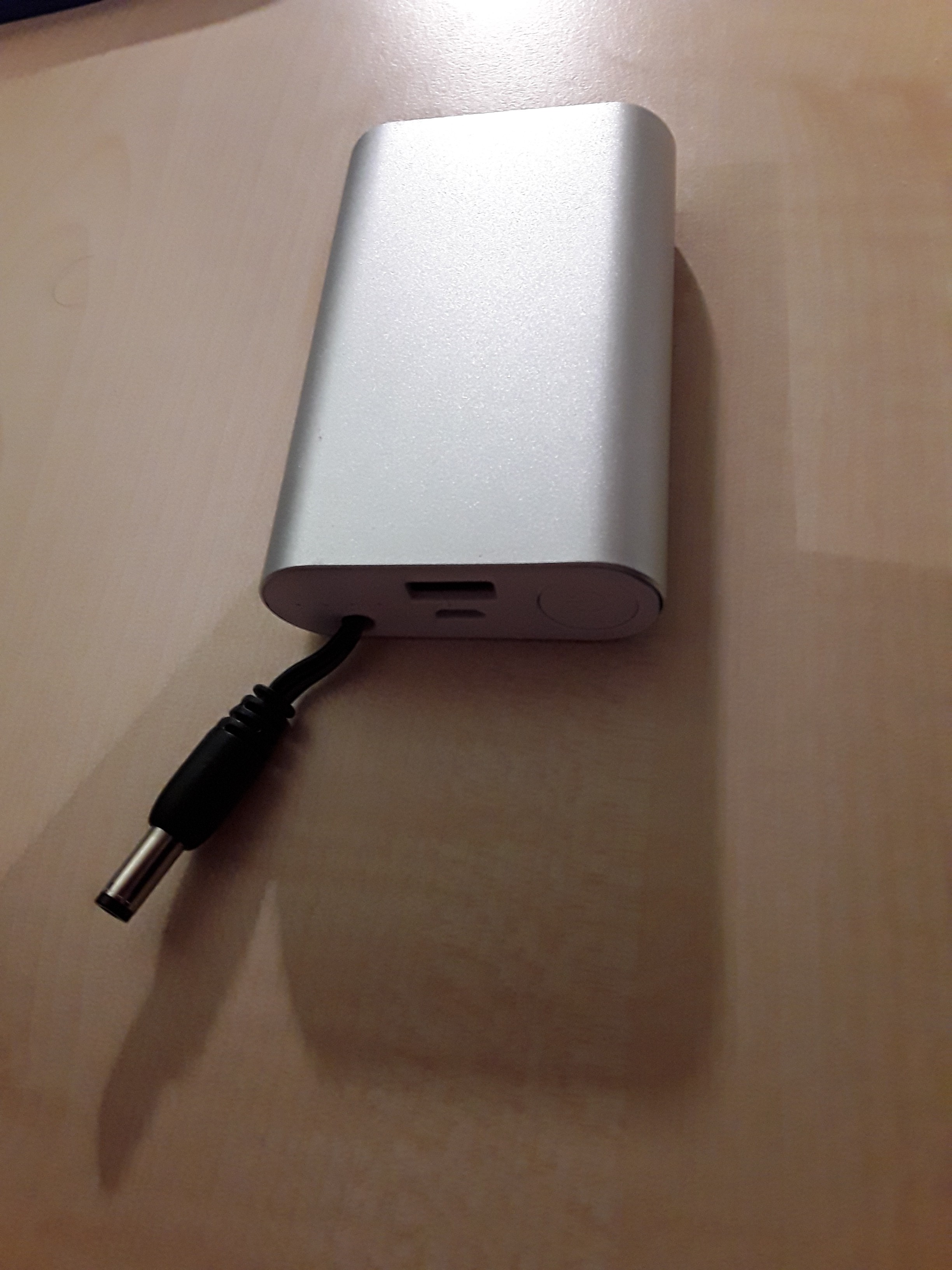
1Making the 10000mAh USB power bank
You could simply buy an USB power bank if you wanted to. However, they are overpriced most of the times and you have no idea about the quality of the cells. The cell type used here has been tested thoroughly by independent consumers.
![]()
At nkon.nl, you can order the Samsung cells with solder lips. These lips can then be soldered to the power bank case kit. It provides a more reliable contact than the provided springs. The shell of the power bank case kit is conductive. Make sure you won't create short circuits upon sliding the outer shell over the power bank.
I added a DC jack to power devices. It's more reliable than the built-in USB A connector.
Only put in cells that you just ordered or have been recovered from the same laptop battery pack. Their cell voltage should be nearly equal. Measure it.
Try out the power bank before you close it. Once closed, the power bank case kit can't be reopened without damage.
-
2Electronics
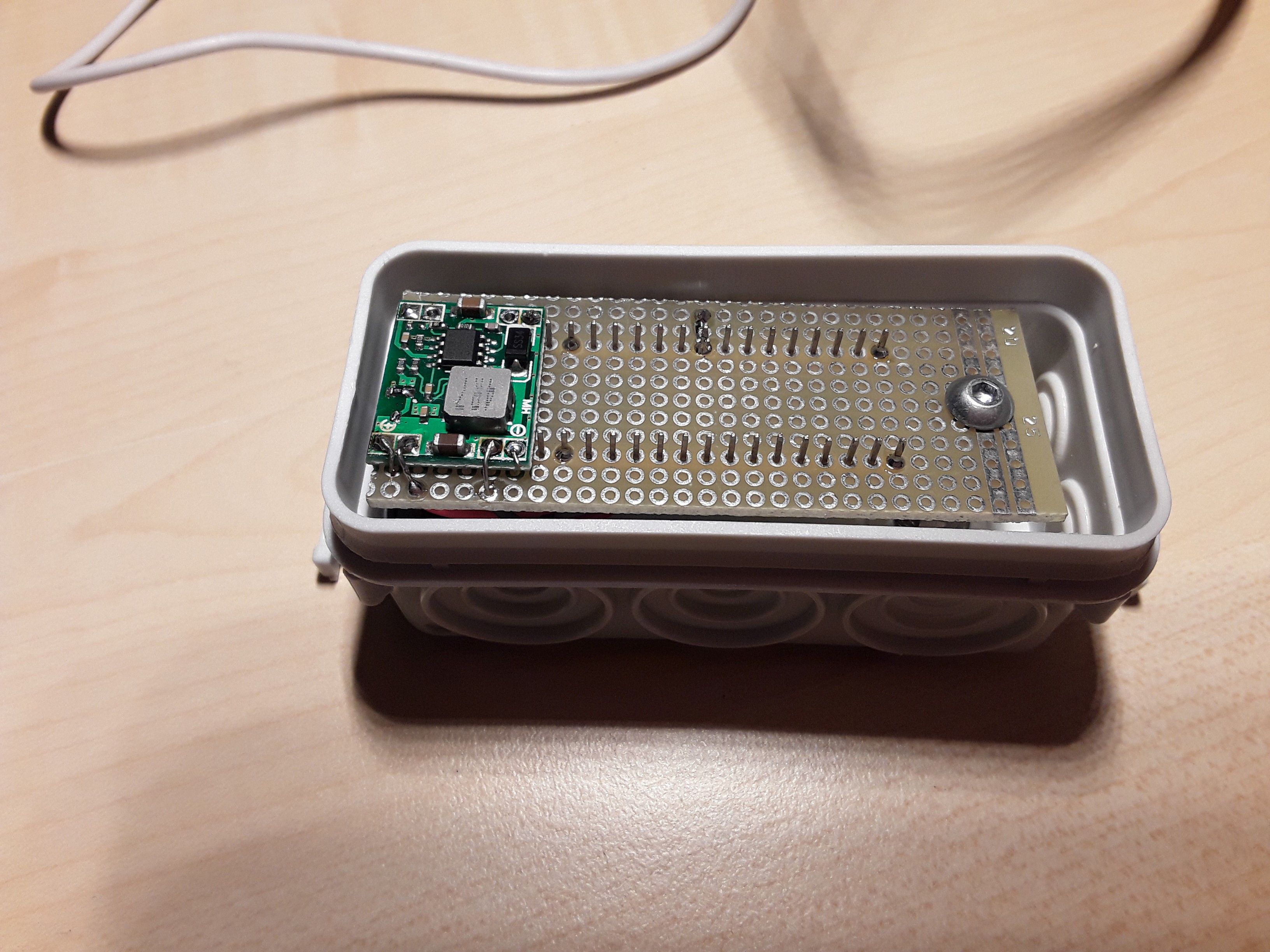
Saw the perfboard to size with an iron saw and drill a hole in it so that it can be fixed inside the controller box.
See how you can arrange the buck module and Blue Pill best on the perboard. I had to remove a few pins from the Blue Pill to make it work.
Set the voltage of the buck controller to 3V3 and connect it to the 5V pin of the Blue Pill. Solder a 220ohm resistor to pin A7 from the Blue Pill. This will be the data pin. Don't forget to connect GND...
-
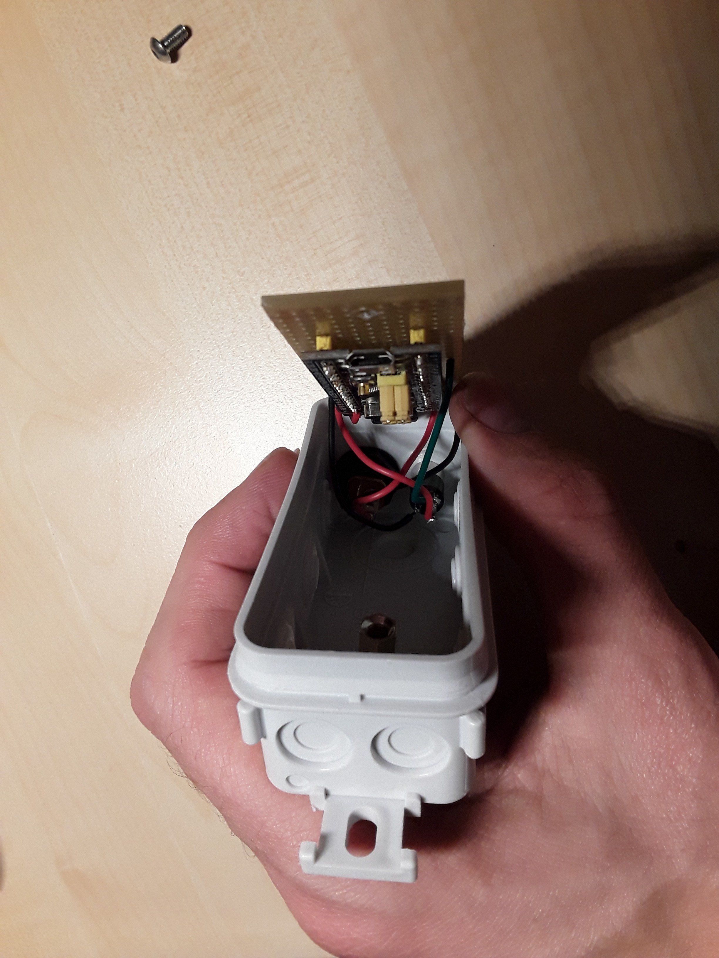
3Controller box
![]()
Make two holes in the side, one for the power jack and one for the audio jack. Make another hole in the bottom to mount the perfboard on.
Mount the M4 spacer, solder the connectors to the electronics.
Check your work by connecting it to the LED string before closing the box.
![]()
-
4Sticking tape on the bike
Cut the LED strips in six pieces:
- 2x 80cm
- 2x 60cm
- 2x 50cm
Apply double sided tape on the transparent window of the bike cover. Stick the 80cm pieces on top, the 50cm pieces at the back and the 60cm pieces on the sides.
Remark the orientation of the LED strips. The LED sequence is as follows:
- Start
- Left side piece: from steer to steering wheel
- Left back piece : from bottom to top
- Left top piece : from top to bottom
- Right top piece : from bottom to top
- Right back piece: from top to bottom
- Right side piece: from steer to steering wheel
- End
-
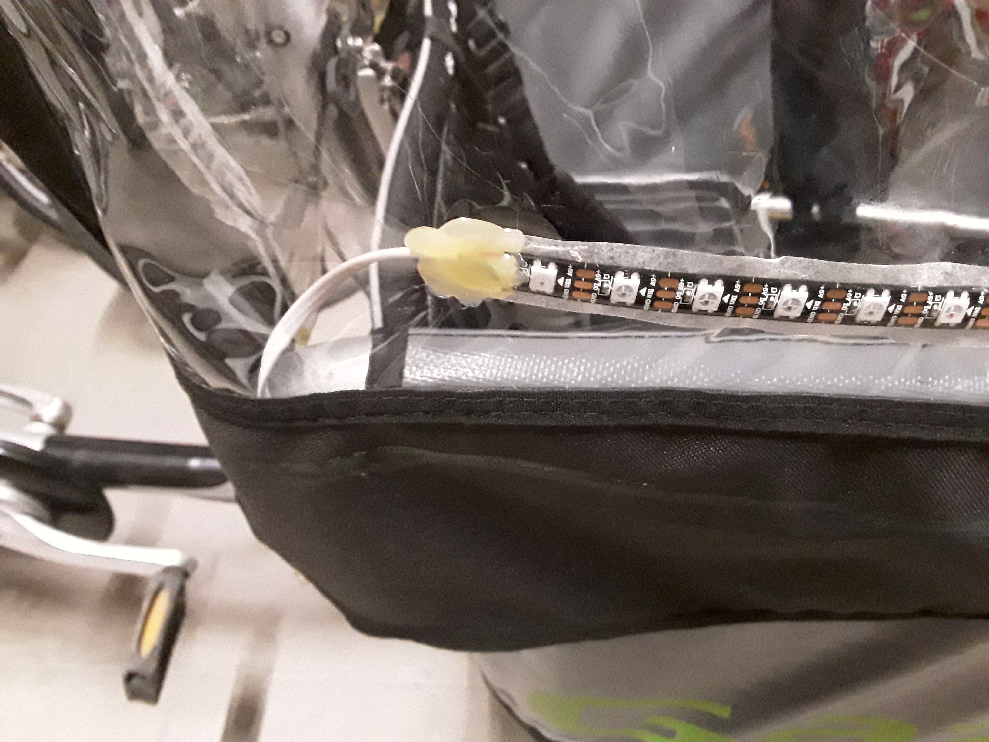
5Attaching the wires
The telephone wire has four wires, of which only three will be used. Make a hole in the transparent bike cover at the end of each piece of LED string. Put the telephone wire through from the inside. Solder it to the LED string (Red=VCC, Black=GND, Green=data).
Be careful with the soldering iron. It easily melts holes in your bike cover.
Attach an audio jack to the beginning of the LED string.
Before covering it all with hot glue, check if it all works.
Finally add the glue on the outside and inside of the bike cover. First apply glue to the bike cover, push the wire in it and cover it with some more glue. Keep it still until the glue has cooled enough to set. Otherwise you'll get holes in your glue.
![]()
-
6Adding audio connectors (optional)
The bike cover consists of three pieces. If you want to be able to swap the middle piece, you'll have to cut the interlinking telephone wire and insert the audio jack and socket.
Light my Cargo Bike
Adding addressable LED string to a cargo bike to be more visible in the dark.
Discussions
Become a Hackaday.io Member
Create an account to leave a comment. Already have an account? Log In.