-
11: make pcb
![]()
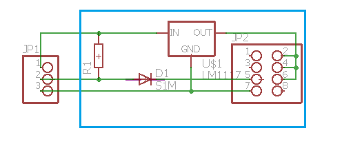
The board is very simple. It is a 3.3V regulator for the ESP. A diode from the output pin and a pull up from the diode to 5V. This is to lift the signal level before putting it in to the led strip.
Some capacitors may be a good idea. My clock is working fine without, using only the caps in the PSU and the module itself. It could also be nice with a resistor to vcc (3.3V) from gpio0 to prevent the module going into programming mode.
The blue rectangle on the schematics indicate the direction of the esp01 module. The three pin connector to the left is the connection to the led strip. 5v at top. Signal in middle and gnd at bottom
-
22: Program the ESP
Follow the instructions on the github page for the tasmota software.
There are precompiled binaries that is easy to use, but as i live in Norway and we have summer and winter time i had to adjust the parameters for the summer/winter time in the user_config file before i uploaded the software from the arduino ide.
I also put my network credentials in the config file.
There are many ways to do this, so check the instructions from Tasmota.
-
33: 3d print
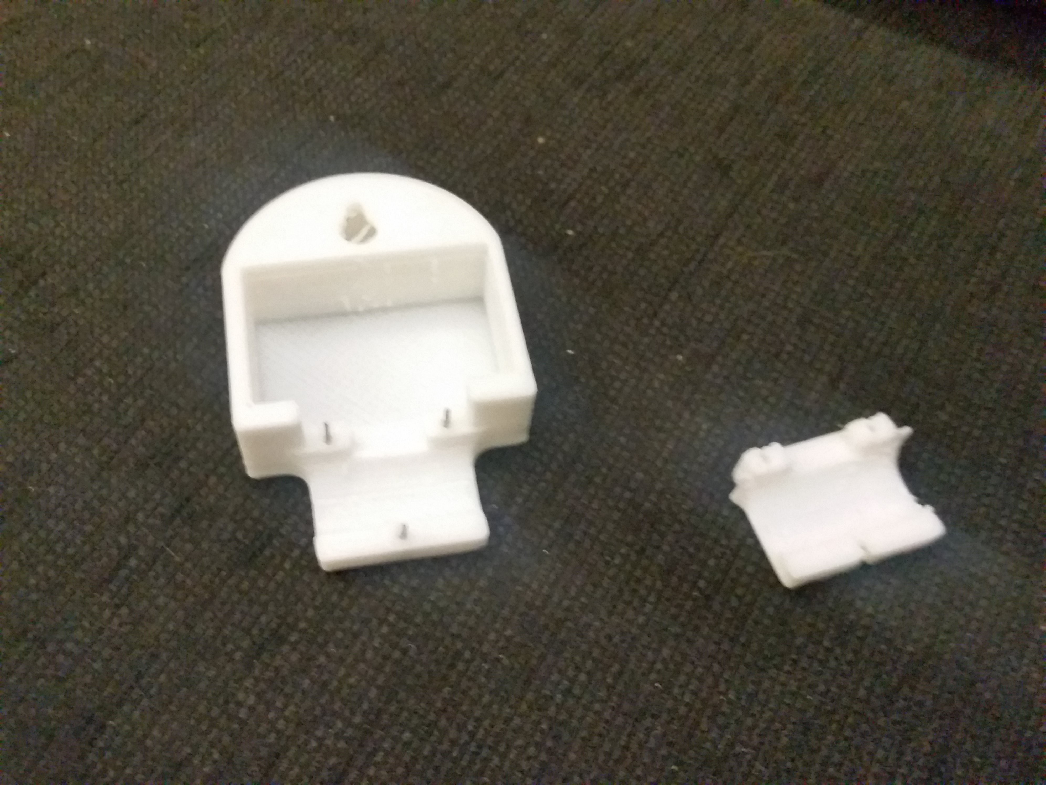
I have 2 stl files. One for the electonics enclosure / hanger, and one for the clip to fasten the enclosure to the clock face.
![]()
The clip and enclosure has 3 holes. I glued in 3 pins from a pinheader. the two that is in line is there to hold the clip in place. the third is going to go trough the clock face.
The stl files are in the files section.
-
44: make clock face
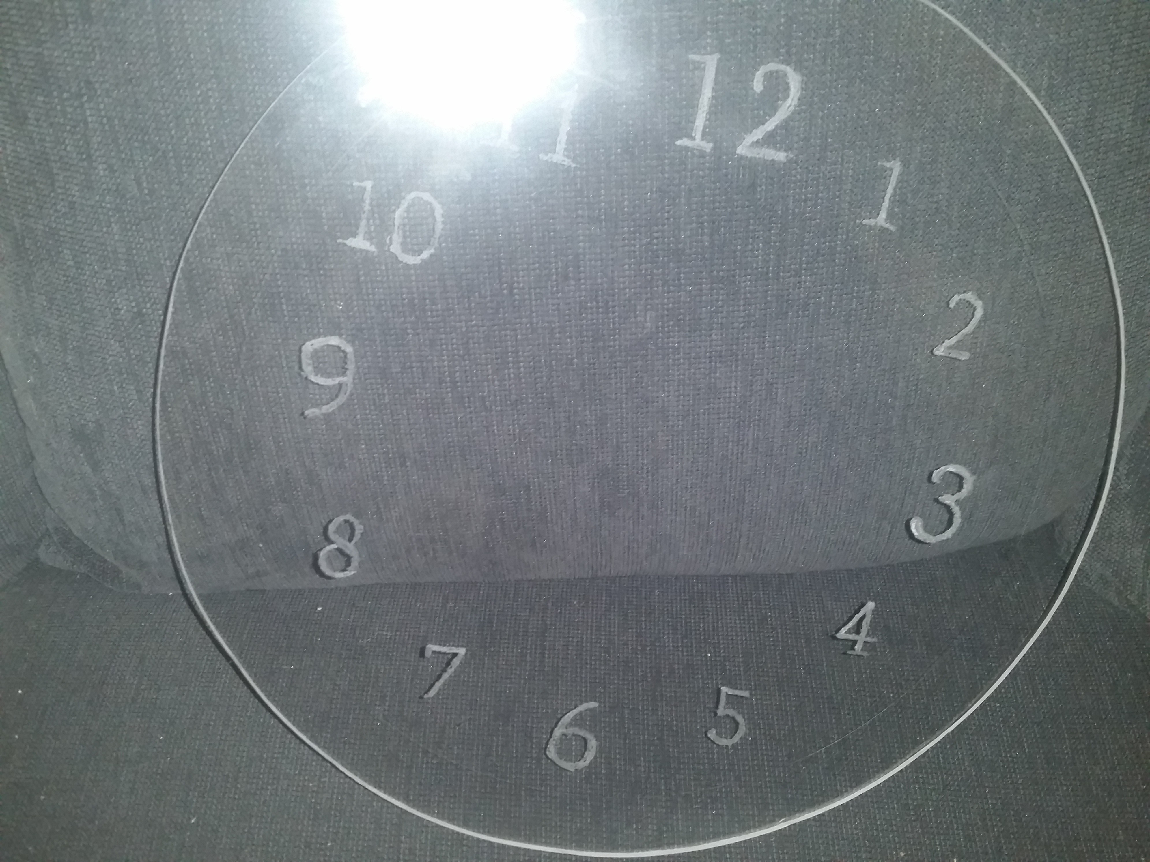
The clock face is made in plexi glass. Diameter 31.4cm (1m led strip / pi - 2 x 2mm thickness of led strip)
![]()
The numbers was written on computer font size 96 and font size 120 for 12,3 ,6 and 9. I put the print out under the plexi glass and used dremmel on the back side of the glass. Print the numbers backwards/ reflected ..
-
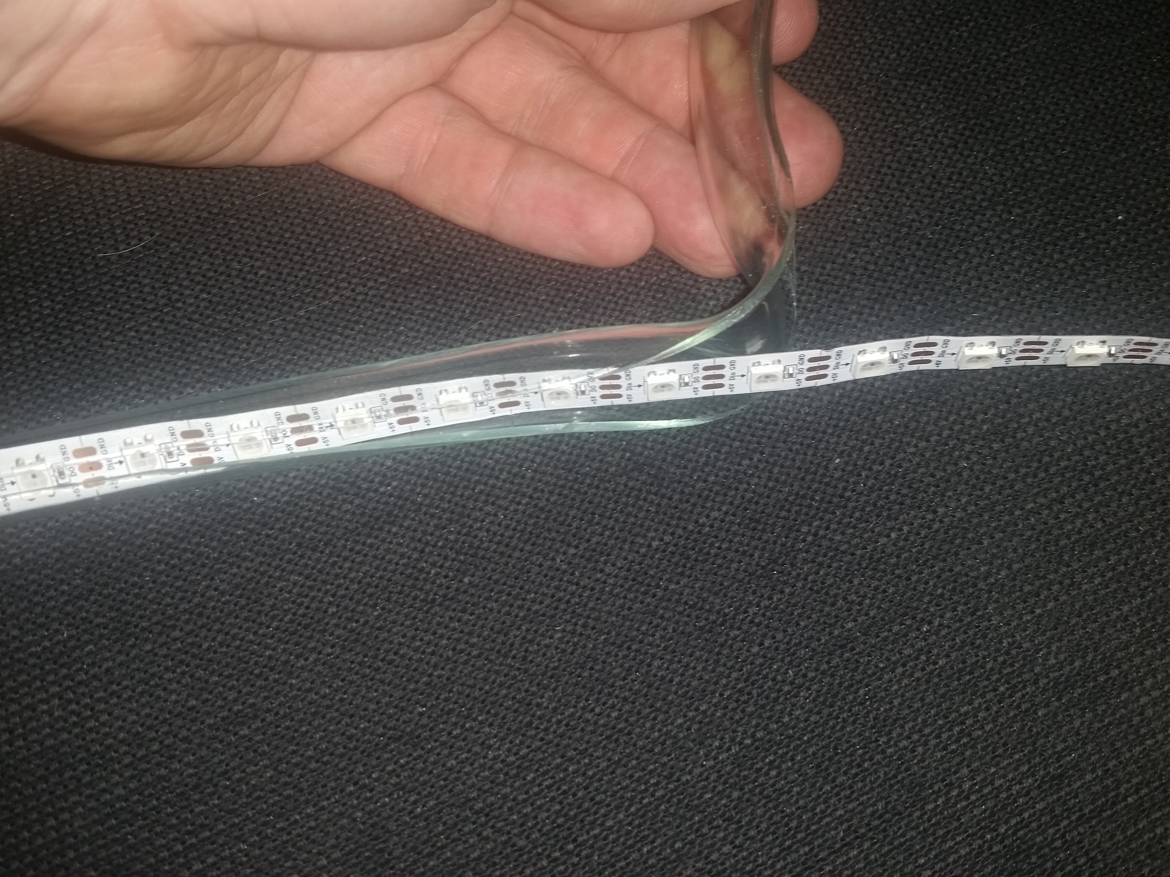
55: make "tire"
Around the clock face i have used a clear tube. split on the inside of the curve. This tube will hold the led strip in place. Note also the hole at the half length, it is for the power cable.
![]()
![]() Cutting a small hole for power supply cable.
Cutting a small hole for power supply cable. -
66: Put it all together
Put the led strip around the perimeter of the clock face. Leds facing inward. Have the ends of the strip on top. connect 5v from both ends to eatch other. The same with GND. Then conect Gnd, 5V and DI to the pcb.
![]()
on the bottom connect the power supply wire to 5V and Gnd. Double check polarity before any conection to power.
Thread the clear tube around the clockface to hold the led strip in place.
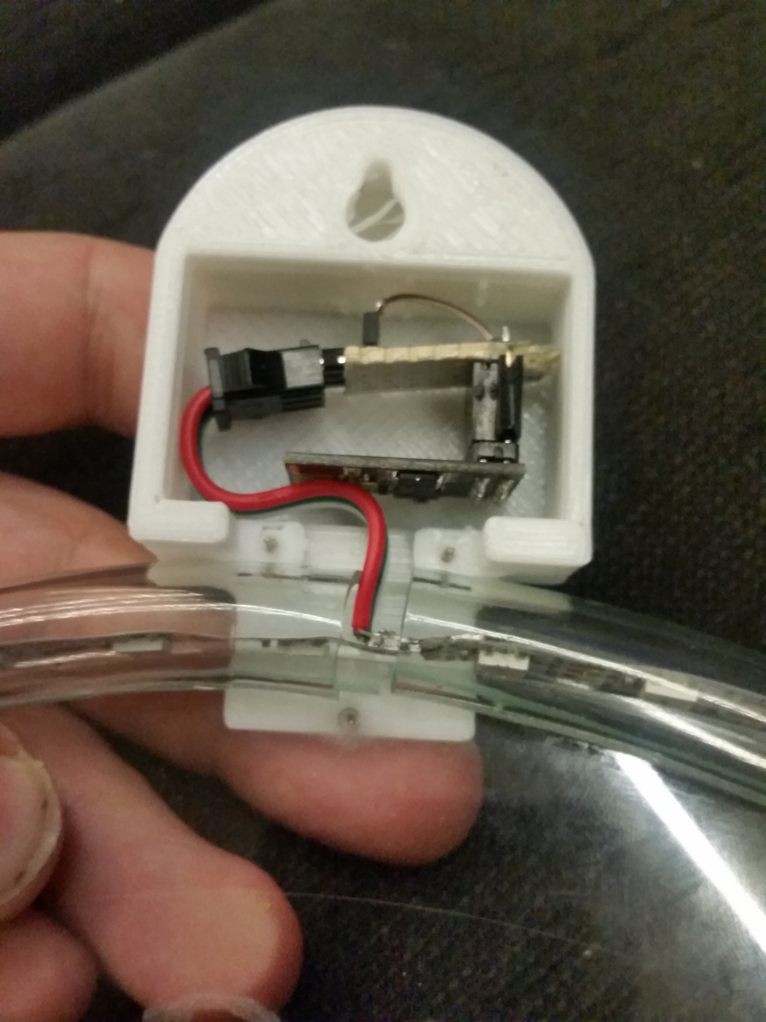
![]()
Clip on the 3D printed case on top to hide the ends of the tube and the electronics. Bending it backwards as in the picture opens it up so the led strip don't get ruined when sliding the tube over.
![]()
-
77: Power up
Power it up!
-
88: Configure tasmota software
Find the ip-adress of the esp.
- this can probably be done in your routers status pages
- or if you leave the esp in the programmer and boot it up while you are in a serial terminal it will show you its ip-adress
Use a browser and go to the ip-adress
go to configure - configure module.
select module type 18 WeMos D1 mini
select SAVE and let the module rebootgo to configure - configure module.
set GPIO2 to 07 WS2812
select SAVE and let the module rebootgo to console
run command: scheme 2 ... to select ws2812 clock moderun command: Pixels 60 ... to set number of ws2812 pixels
run command: Timezone 99 ... to select right timezone (from -12 to 12. 99 meaning with summer/wintertime from config file)
Check out the rest of the config options to conect it to MQTT, domoticz or other.
ESP and WS2812 based clock
Stylish clock project based on an ESP-01 module with arendst - tasmota software

 Cutting a small hole for power supply cable.
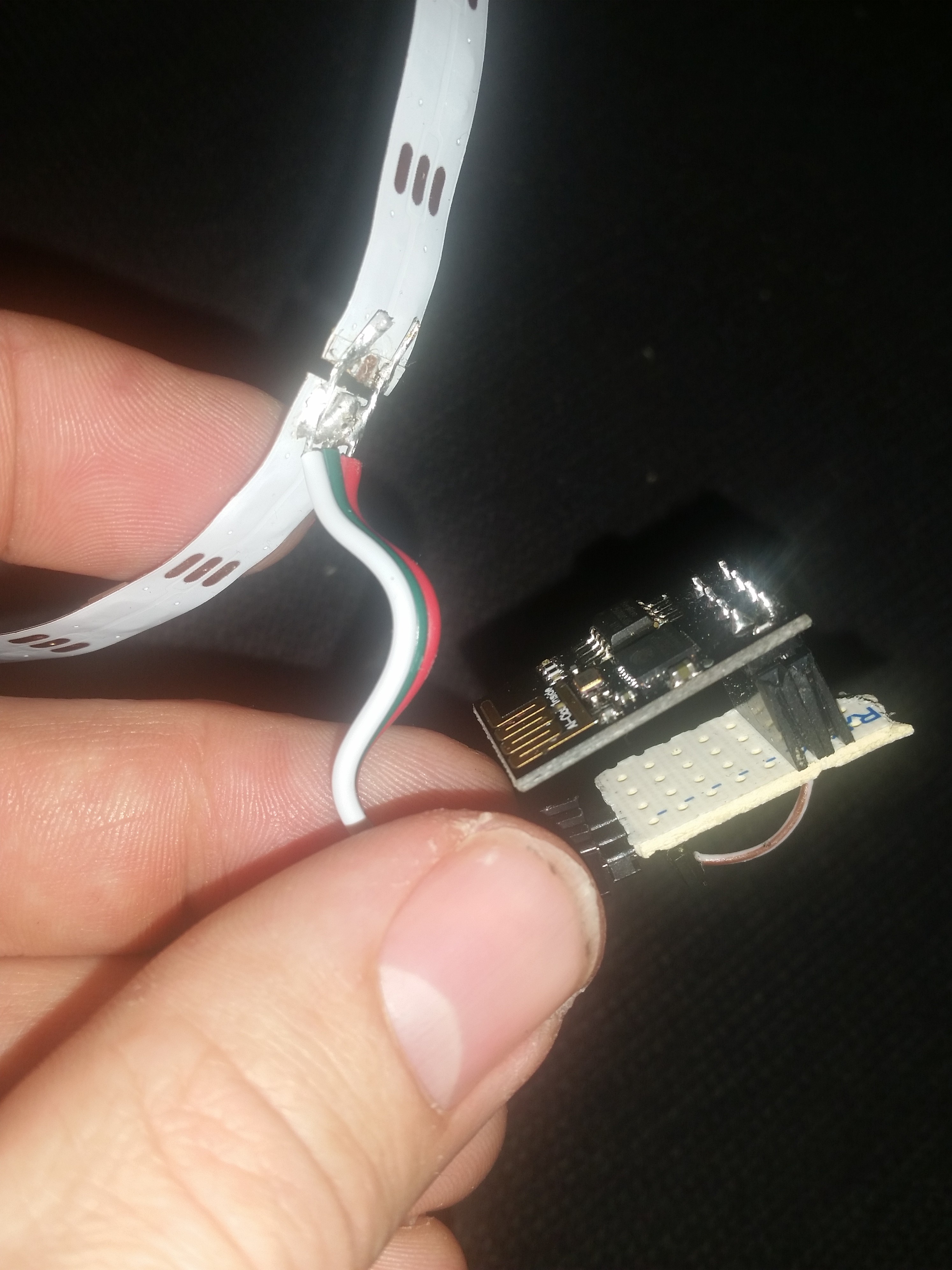
Discussions
Become a Hackaday.io Member
Create an account to leave a comment. Already have an account? Log In.