Things have been moving along a bit slow on this project of late but some progress has been made this week on the circuit design.
Primarily this is a NodeMCU board with a bunch of IO associated with it. Normally I would have just copied and pasted the IO stages of other projects and the job is done but.. I’ve taken the opportunity to jump from using Eagle (which I’ve alsways hated anyway) over to Kicad and I hope I find it more palatable than Eagle. I cut my teeth doing circuit design on Protel 98 I think the version was but with no Mac equivalent about when I made the switch from windows to MacOS (7.6 I think it was) I didn’t have many options.
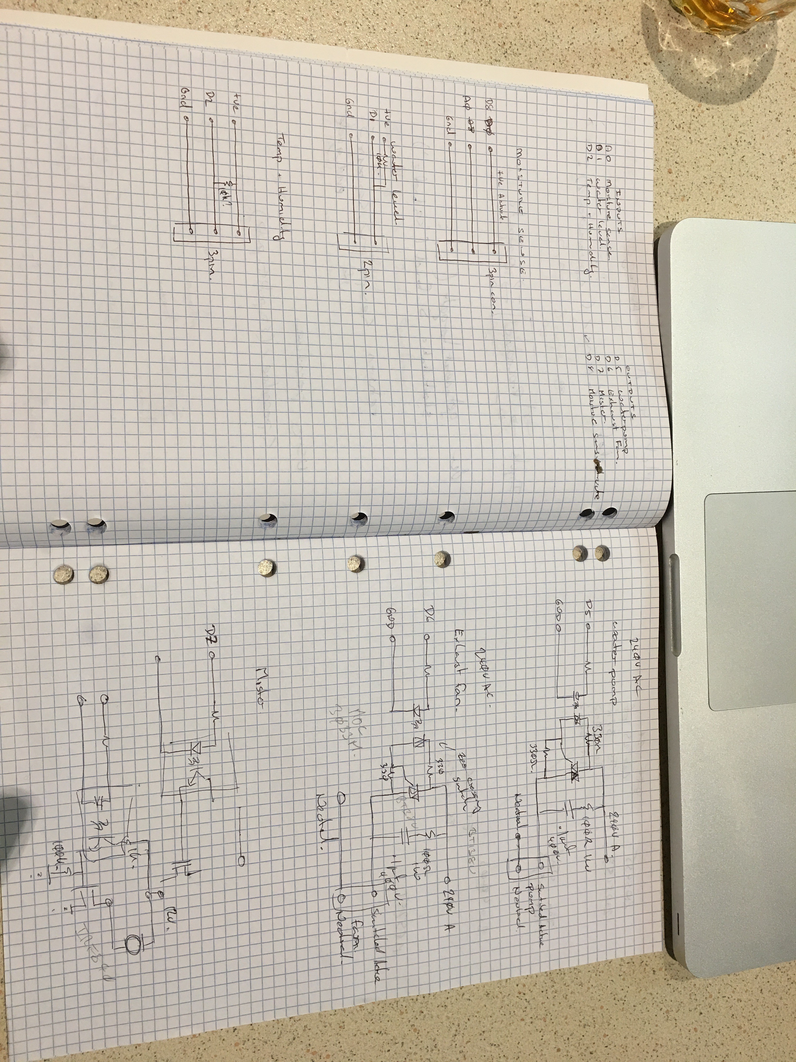
So to get the ball rolling while I come to terms with libraries and the like in Kicad I’ve reverted to sketching the IO stages on paper while I make my component selections than I’ll input it all into Kicad for the schematic capture and board creation.
Inputs are pretty straight forward sensor connects via a connector to the board and wired directly to the NodeMCU. In this case Im expecting the sensors to be fairly close to the board if not directly on it so at this stage I am not considering anything more than clamping diodes to keep induced signals to within the power rails.
Outputs are switching primarily 240V AC devices so opto isolated Triac drivers and Triacs are the order of the day.
At this stage MOC3033 opto isloated zero crossing triac drivers will be used to switch the BT138 600V 12A Triacs - serious over kill for this application but the cost difference for a lower spec triac is pretty negligible and this gives me the advantage of repoursing the circuit for other things :)
The DC switching will also be opto isolated (TLP185) coupled with an IRF840 500V 8A MOSFET as a high side switch. Again a fair bit of over kill but will lend itself to other projects requiring a higher voltage range and more power.
 Saabman
Discussions
Become a Hackaday.io Member
Create an account to leave a comment. Already have an account? Log In.