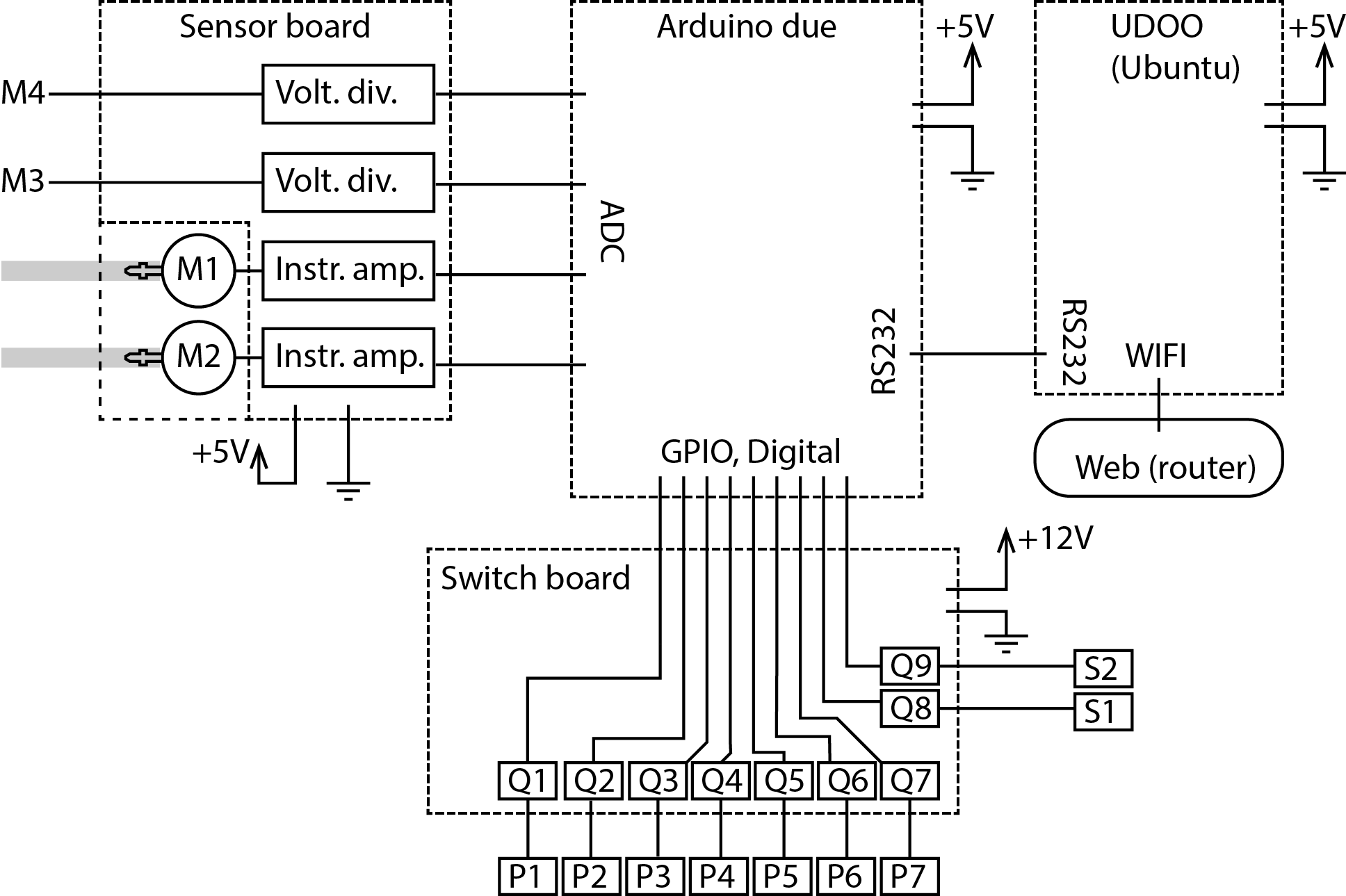
Connectivity schematics for the electronics (with device codes from the process schematic) below. "UDOO" is a tiny PC with embedded arduino due, although I'll be using a separate due board. "Volt. div." is a voltage divider circuit for matching the sensor output to the ADC voltage limits, and "Instr. amp." is an instrumentation amplifier. "Q1"--"Q9" refer to switches, most likely power MOSFETs. Dashed line shows the individual boards; I'll place the pressure sensors (i.e. water level sensors) on the board in order to have the amplification as close to the sensors as possible. I'll make the final schematic with eagle once I've chosen the components. Next-up: Software

Discussions
Become a Hackaday.io Member
Create an account to leave a comment. Already have an account? Log In.