To make the experience fit your profile, pick a username and tell us what interests you.
We found and based on your interests.
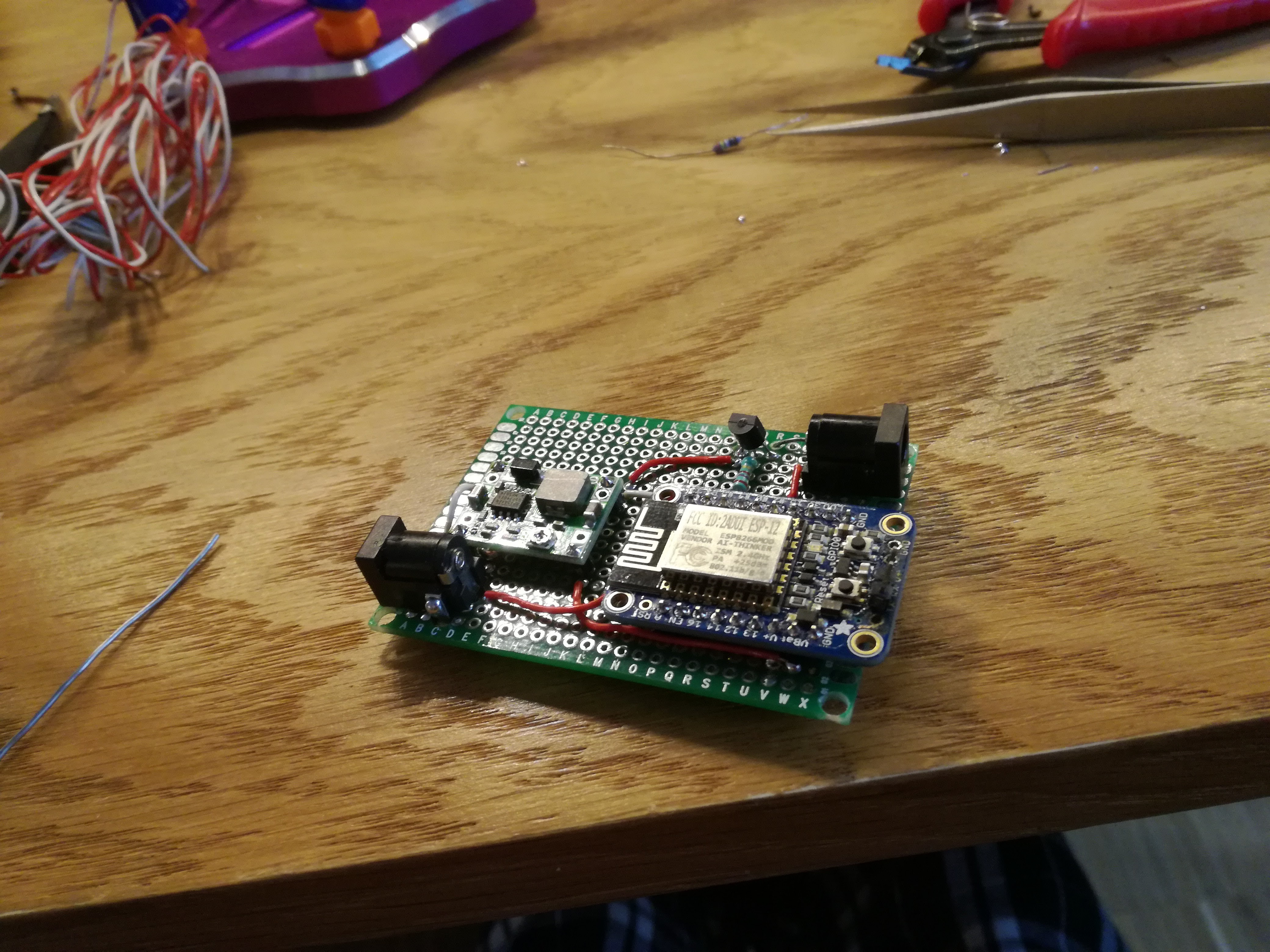
I am not really a fan of breadboards, but for a design so trviail I really didn't feel like spending time and money to produce PCB. I hooked up everything on my desk and got it running in no time. The whole thing should be enclosed anyways, so it doesn't matter if it's ugly or not.
I also did some power optimization. Instead of linear regulator I got $0.80 MP1484 step down module from e-bay. I felt kinda terrible to allow 12-5=7V drop across the poor component. With current bursts of up to 500mA, I can only imagine how short the linreg would survive. 
Complete code so far:
// Adafruit IO Digital Output Example
// Tutorial Link: https://learn.adafruit.com/adafruit-io-basics-digital-output
//
// Adafruit invests time and resources providing this open source code.
// Please support Adafruit and open source hardware by purchasing
// products from Adafruit!
//
// Written by Todd Treece for Adafruit Industries
// Copyright (c) 2016 Adafruit Industries
// Licensed under the MIT license.
//
// All text above must be included in any redistribution.

/************************** Configuration ***********************************/

// edit the config.h tab and enter your Adafruit IO credentials
// and any additional configuration needed for WiFi, cellular,
// or ethernet clients.
#include "config.h"

/************************ Example Starts Here *******************************/

// digital pin 5
#define LED_PIN 0
#define ventilator 5

// set up the 'digital' feed
AdafruitIO_Feed *digital = io.feed("xxxxx");
AdafruitIO_Feed *state = io.feed("yyyyy");

void setup() {

  // set led pin as a digital output
  pinMode(LED_PIN, OUTPUT);
  pinMode(ventilator, OUTPUT);

  // connect to io.adafruit.com
  io.connect();

  // set up a message handler for the 'digital' feed.
  // the handleMessage function (defined below)
  // will be called whenever a message is
  // received from adafruit io.
  digital->onMessage(handleMessage);
  // wait for a connection
  while (io.status() < AIO_CONNECTED) {
   digitalWrite(LED_PIN, LOW);  // toggle LED during connecting phase
   delay(500);
   digitalWrite(LED_PIN, HIGH);
   delay(500);
  }

  // we are connected
   digitalWrite(LED_PIN, LOW);
   delay(3000);
   digitalWrite(LED_PIN, HIGH);
   state->save("Active");
}

void loop() {

  // io.run(); is required for all sketches.
  // it should always be present at the top of your loop
  // function. it keeps the client connected to
  // io.adafruit.com, and processes any incoming data.
  io.run();

}

// this function is called whenever an 'digital' feed message
// is received from Adafruit IO. it was attached to
// the 'digital' feed in the setup() function above.
void handleMessage(AdafruitIO_Data *data) {

  // write the current state to the led
  digitalWrite(ventilator, data->toPinLevel());

}
Create an account to leave a comment. Already have an account? Log In.
Become a member to follow this project and never miss any updates
By using our website and services, you expressly agree to the placement of our performance, functionality, and advertising cookies. Learn More