-
Random syncing thoughts
04/23/2018 at 05:58 • 0 comments![]()
Part of me has gained quite a bit of interest in trying to implement this thing (at least read-back) with discrete logic, like TTL/7400-series.
Sync: There's no reason it has to be the same duration as a PWM-nibble. 4us seems better to me.
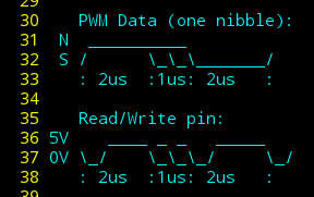
The key concept of the sync pulses is to make it easy to detect which falling-edge from the Read-Data pin corresponds to the start of the PWM cycle.
Here, for sync, the falling-edge pulses occur farther-apart than they would in a PWM-data nibble. So, 4us is plenty.
Clock-syncing: 1us is divided into 16 possible values... so 16MHz sampling, roughly.
"Roughly" because, realistically, it'd be kinda absurd to expect a floppy to spin at *exactly* 300RPM, or even exactly the same RPM each time it's accessed. And, frankly, it's entirely possible the spin-rate may vary several times per revolution!(e.g. the disk is worn in a spot that drags differently on the read-head). So it's actually rather necessary to have some amount of flexibility in the reader/writer's sampling-frequency, which means somehow adjusting that frequency to match that on-disk.
I've been neglecting that part, for simplicity, assuming that the spin-rate on the same drive/disk will be relatively constant most of the time...
So, now, two potential branches for the course of this project. A) get it working as simply as possible... That was the original goal... And, part of the intent behind that is to demonstrate possibilities to those who may otherwise be intimidated B) essentially rebuild the entire floppy-system from scratch, for the sake of learning, I guess. E.G. I've always kinda wanted to figure things like PLLs out, at a low-level... Now I'm thinking about how that'd work... to synchronize a clock with a pulse that's 64x slower (if I use 4us for syncing)... I've a vague idea of a 7bit counter, a <=> comparator, and... what for actually generating the clock? I think the norm is a voltage-controlled oscillator... But, then, it occurs to me the same could be done with an AVR and the OSCAL register, realtime varying of the AVR's clock to match a varying-frequency external source... weird concept, but kinda intriguing, potentially very useful... And... not at all in-line with the TTL-idea.
I guess this is how my brain works, or doesn't.
Anyways, TTL-implementation is more a thought-experiment, for the time being. Actually, the whole project is, so-far... Been meaning to solder up that proto, and get coding, but it never seems like the right time/setting, these days.
So, 4us for sync-pulses, 6-bit counter. Data is only valid during the 1us window between 2us and 3us after the start of the PWM cycle... that fits within our 6-bit counter, as well.
Now, here's a thing I'd briefly pondered in the past: After the Data-edge occurs, we really don't care where the next PWM-start-edge occurs. It just has to be at least 2us after the data-edge. Thus, our counter needn't go higher than 48... it'll get reset to 0 at the next PWM-start, whenever it occurs.
So, one potential benefit of this (dependent on the write-mechanism, and its alignment with the read-head), is the possibility to modify individual nibbles. Maybe a stretch, or maybe not... e.g. bumping the 'buffers' to 3us might allow for it, reliably.
Another potential benefit is increased capacity... if you're writing a lot of 0's, each nibble is only 4us, a lot of 0xf's would be 5us, each. Handy, then, for Write-Once, Read-Many drives, like a CD or movie. Not so much for read/write media.
In the case of this frame-buffer, it makes sense to keep every nibble the same length, for the sake of a steady pixel-lock (which isn't really necessary with this display).
But, anyhow, with a counter limited to 48 or 64, not requiring a specific duration for every nibble, those options are possibilities. Simplify the thing, open new doors, I guess. OTOH, with specific-width PWM cycles, clock-syncing is inherent to every nibble... which ain't a bad thing.
Oh, I should mention, the idea of sync-pulses is to only use them (several, probably) once at the beginning of a long data-stream... E.G. immediately after the index-pulse. And, if I go the route of sectors, then once before each sector.
And, again, the main reason for them is to indicate which edges are which, clock-syncing was just a side-effect.
Yeahp.
I'm sure I had more thoughts, but I've lost 'em.
----
Oh... back-to-back data... yeah, that'd be hard to keep a clock sync'd to. but not impossible. Especially with regular sector/sync headers. definitely potentially useful for WORM drives... yahknow, where there's no PWM-start pulse. e.g. a 2us duration from the last value-pulse to the next indicates 0x0, and a 3us duration indicates 0xf. Nearly double the capacity, anyhow.
-
PWM-sync OBVIOUS!
04/21/2018 at 07:39 • 0 comments"How'm I gonna know which edge corresponds to the start of a PWM cycle, and which to its duty-cycle?"
![]()
-
160+ 'sectors'?
04/21/2018 at 05:30 • 0 commentsjust an idea...
a brief intro to the problem: one of the dilemmas of trying to load an image onto each track is that the entire track/image would have to be written in one fell-swoop, in realtime. This because it'd be darn-near impossible to expect the read and write heads to be aligned so perfectly as to be able to manipulate individual bits on the disk...
This, I presume, is a huge factor in why disks are written in sectors. 512 bytes of consecutive data, prepended by a header that gives info about that sector, and that header prepended with numerous repeating bytes which indicate the beginning of a sector, allowing the controller to resync its clock with this new and likely misaligned stream of data. (Misaligned with respect to the previous sector, as each is typically written in different rotational-cycles).
Writing the whole image-frame in one fell-swoop would be challenging... The uC itself probably isn't fast enough to render in realtime, so I was planning to send images from a host computer... but the math wound up requiring a serial connection at 1Mbps. That should be doable. The problem is that that data stream can't be interrupted, e.g. if the host computer decides to task-switch to handle a mouse movement.
I'm sure it's doable, a receive-buffer would help, xon/xoff, a faster baud rate, 'renice' at a high priority, a custom downloader program, a few other things.
But, not ideal... Also because it means the only images that could be stored would have to be pre-rendered... and, again, loaded from a computer.
So, it occurs to me... Why not write the floppy in chunks... yahknow, like... sectors! Duh.
----
Here's the thing, I know all about sectors... I was trying to avoid them, for the sake of a simple demo... The uC would've basically been doing nothing more than could've been handled with a few TTL parts, in translating the stream of PWM data coming from the Floppy drive into the parallel data-bits required to drive the display-timing and draw the image. I like that idea.
... So, I've been avoiding sectors. But, the fact is, I *will* be using a uC in this project... at least for writing the images to disk, And then, for readback, because the hardware would already be set up. Also, the solution to the other day's 'duh moment' would be a bit more difficult to do with TTL.
------
But, tonight occurred to me that a stripped-down sort of 'sector' could be quite easy to implement. What if *every* line was a 'sector'... my display is 160 lines tall. So, after each Hsync, maybe the uC just writes a bunch of Hsyncs repeating. When read-back, the first latches the uC's Hsync output signal and indicates to the uC to resync the PWM-data, etc. Then the beginning of the next line of data will overwrite some of those repeating Hsyncs with a short header just long enough to assure the PWM-data is being read correctly, then the uC will switch Hsync off when appropriate, beginning the next line.
This'd be easier than regular sectors for a ton of reasons, one of which is that there's 16 possible PWM-data values in each PWM-nibble, but only 9 or 10 are allocated (8 colors, hsync, maybe vsync). Thus, the beginning of the next line/sector-data could be prepended with an 'hsync-off' nibble. Easy-peasy.
This is all further aided by the fact that the 'sectors' will always be read-back sequentially and in realtime. Older computers, of the era when floppies were invented, just couldn't handle that much processing... floppy controllers were even dumber. They couldn't process two sectors back-to-back (thus interleaving). Further still, there was no hard requirement that sectors would always be a certain lenght! So, sector-headers had to contain enough information to be located at-random. Here there's no need for all that. These 'line secctors' are all sequential and all the same length. A line-data-header, here, could probably be no more than 4 PWM-nibbles, just enough to resync the PWM-data 'clock', and maybe contain the hsync-off value.
So... the hsync pulses may vary slightly in duration, but that shouldn't matter to the LCD... And as far as a TTL-implementation, I think it'd only add a latch and a 'match' (what're those called, 4-bit comparator?). *maybe* an 8-bit counter and comparator and some glue... ok, getting uglier.
But, the resyncing bit,.. from the 'duh moment'... (that would also be necessary/reused here)... that's still an unknown in the TTL-implementation realm. Counters, comparators, latches. Maybe not so bad, but on the same scale as the entire rest of the circuit :/
.....
Anyways, a side-benefit, of course, is that now the AVR could actually use the floppy as a frame-buffer for images of its own rendering... which opens up a lot of doors. Maybe a Mandelbrot set, maybe a zoom... 160 frames, yo!
...
But... Also feature-creep... TTL-translation was kinda exciting, 'duh moment' might've ruined that :/
-
'duh' moment...
04/16/2018 at 08:37 • 2 commentsOK, but there's really no [easy] way to determine whether we're looking at the *start* of a PWM cycle, or the falling-edge of the duty-cycle, itself... because: every edge is stored as a falling-edge.
This doesn't matter for *audio*, because an inversion in the PWM output-signal results in an inversion in duty-cycle, around 50%... and *that* is nothing more than an inversion in polarity on the speaker-cone, which doesn't matter when only dealing with mono.
But for *data* (e.g. the image-frames), we definitely need to keep track of which falling-edge corresponds to the beginning of a PWM pulse, and which corresponds to the duty-cycle's edge.
I feel like I must've figured this out once before...
Best I can come up with is to align the PWM with the "Index" output (which occurs once every rotation). But, that may be iffy, as well... E.G. the Write-head and Read-head may not be perfectly aligned... in which case, writing at the start of an index-pulse may be read-back after! Oy! Then, of course, the odds of the "index" outputs on differing drives being perfectly-timed with the read/write-heads... Even less likely.
Some amount of reconstruction should be possible... e.g. let it run for several pulses, then figure out which edge occurs at the same period, then that's the PWM-start edge. But... well, anyways, it's getting a little more complicated.
An interesting artifact will occur when switching tracks... (e.g. data will be garbled while the head races to the next track, *but* the screen will most-likely continue to refresh with that garbled data since the uC will be regenerating the pixel-clock... but hsyncs will be missed, or even randomly-injected...) I've looked forward to seeing that. And with this new dilemma, it could be even more interesting (e.g. colors may be inverted for one frame, even after the read-head has stopped seeking).
Frankly, I consider these things to be one of the major driving-factors for this project... I already know the project should work as-planned, with maybe a few unexpecteds which can likely be worked-out... But these other things, probably not *useful* per-se, but hard to predict, so akin, maybe, to the draw to watching a flame. And sometimes these sortsa things wind-up being *very* useful... Moldy bread, yahknow? Moldy-milk, Moldy grapes, Moldy oats-grains-and-hops... Post-its! (oh, wait...) Once it's running, I'll probably spend more time looking into that stuff than actually making it useful (turning it into a game, etc.) If nothing else, maybe I could use it as a random-number-generator...
--------
Another idea, (I feel like I'm reinventing the standard method) is to have a "header" at the start of each track, immediately after the index-pulse. This'd contain a string of PWM-values with the same (not 50%) duty-cycle. Oh No! Wait a minute... It'd have to be *vastly-differing* duty-cycles, from one to the next. Then, use this time to look for the edges which are periodic, as described earlier.
The original plan was to use the "index" pulse *as* the Vsync pulse... Doing-so, here, wouldn't be so useful... Unless, maybe, I choose to use the trailing-edge for Vsync, and the leading-edge for beginning the header. Hmmm.
If that *doesn't* work, then we'd have a string of data that can't be used immediately after the vsync, which'd leave garbled pixels on the first row of the screen. (Which could be interesting, anyhow).
But, it could be that we're back to having a specific nibble-value to indicate Vsync. Not so bad, really. Better, probably, what with the alignment concerns.
And, again, I'm planning on storing 4-bits per PWM-value, that's 16 different duty-cycles within a 1us time-frame, which corresponds to our 16MHz processing-speed. (Or, plausibly, 16 values in 2us, allowing for some lee-way, in case the disk decides to spin at a slightly different rate from time-to-time; due to temperature, maybe, etc. Or different drives...). But, with these processing-speeds, it might be difficult to shove a color-palette in there, so I'd only been planning to use 8 of the values for color-data, and one for hsync... so there's plenty of headroom for other things (vsync).
-
Audio preparations
04/16/2018 at 00:55 • 0 commentsBefore I actually start writing audio (and images!) to disk, I need to make sure my write/read technique/circuitry is "sound"...
I've implemented the test-circuitry via comparators, just for the heck of it. And to (later) demonstrate how easy it is to make use of floppy-data... no microcontroller necessary! But, we're still a ways off from that.
First, the audio is converted to PWM.
Then both PWM edges are converted to falling-edge pulses.
This, then, could be fed directly into a floppy drive's "write data" input, storing the PWM on-disk.
When read-back from the disk, the floppy drive will give these same falling-edge pulses to indicate each edge of the recorded PWM.
That, then, gets fed into my single-comparator T-Flip-Flop, to convert those falling-edges back into PWM, then directly drives a speaker.
-
WIP: MFM (normal diskette) data-storage
04/13/2018 at 04:04 • 0 commentsMost floppy drives use a method called Modified Frequency Modulation (MFM) to store binary data-bits on the magnetic media.
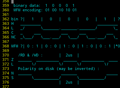
![]()
This method encodes each data-bit into two MFM 'bits'. E.G. the data-bit '1' is always encoded in MFM as "01", the data-bit '0' is either stored as MFM "00" or "10", depending on whether this follows a '0' or a '1' in the previous bit.
This seemingly over-complicated scheme serves several purposes. First and foremost, it assures somewhat regularly-spaced transitions/alternating between North and South polarity on the media, regardless of the binary data stored. Thus, the floppy disk controller is able to keep its serial-data clock synchronized with the data-bits on-disk. Essentially, MFM encodes both the data-bit *and* the serial clock into each MFM bit-pair. This alternating polarity is also essential for the inductive read-head/pickup, which can only detect *changes* in magnetism.
Thus, MFM assures that even 1KB of consecutive 0x00's (e.g. after a format) will be stored on-disk as alternating between North and South, once for every 0-valued data-bit.
------
But, note, again, that data-bit '0' has two separate encodings "00" and "10". If MFM "0110" were written to disk (binary data "10"), we'd have a problem... and this is where things get a bit more detailed, and we need to take a step back and analyze what's actually being stored on the disk.
Each MFM bit represents a potential for transition in magnetic flux. Wow that's badly-worded. Let's try again.
Most any position on the disk surface can either be North-polarized or South-polarized. MFM assures that North and South alternate somewhat regularly. Great!
BUT, placing these opposing polarities too close together can cause problems. Maybe the read-head is too large, picking up two (or three?) polarities at the same time, unable to discern which it's reading. Maybe there's some inherent granularity* in the media? There could be many factors, but as I understand, it boils down to these "magnets," each one MFM-bit wide, attracting and repelling each other.
Here's how I understand it: If you place two magnets on a table, so their North polarities face each other, then those two magnets will repel each other, up to a certain distance, at which point friction prevents further repulsion.
Placing a weaker magnet's South pole between the two would probably reduce the effect, but not eliminate it. The two stronger magnets still repel, and placing a compass above the weaker magnet's south pole will still show a net North polarity.
(*Note that 'precompensation' is another topic entirely, but if granularity was a concern, precompensation wouldn't be possible)
Thus, there is a minimum space which can reliably contain two flux-transitions (three polarities alternating, NSN or SNS). That minimum space is two MFM-bits long, on the innermost track, where the bits are most-densely packed.
![]()
(binary values: High and Low. MFM values: Change and No-Change. Read/Write values: Hi-Z/floating and Low. Polarity values: North and South)
Anyhow, an MFM '1' bit does not correspond to a polarity on the disk, it corresponds to a *change* in polarity on the disk. A "change in flux".
And two changes in flux can only occur at greater than some minimum distance (2us on the smallest/inner track on a spinning disk). Thus, MFM encoding does not allow for a "11" pattern. The first data-bit '0' after a data-bit '1' is, therefore, encoded as "00" rather than "10", giving data="10" mfm="0100", rather than mfm="0110"; no consecutive '1's in the MFM encoding.
All That To Say: diskettes guarantee proper data-retention when each singular magetic polarity is at least 2us long, but also alternates regularly. And, MFM assures that.
-----
So, the shortest single-polarity magnetisation is 2us, two MFM bits long, e.g. between MFM="101" where the new polarity starts immediately after the first '1' and ends immediately before the second... "10" representing two bit-durations of the same magnetization.
The longest single-polarity magnetisation is 4us, four MFM bits long. (Not shown in the diagram). in the pattern MFM="010001" from the data value "101"... MFM="1000" representing four bit-durations of the same magnetization.
These two limiting-cases, obviously by-design, satisfy both the serial-clocking needs as well as the inductive pickup's needs. The latter being most important for my new PWM-data-storage method.
-
PWMing 2
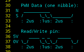
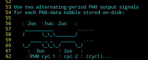
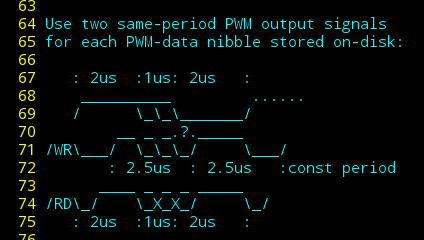
04/12/2018 at 01:29 • 1 commentAgain, we cannot send our PWM *data* directly to the floppy-drive's /Write-data pin. Instead we need to send two falling-edge pulses for each PWM-nibble. Confusingly, I plan to use a PWM-output from the microcontroller to create those *two* precisely-timed falling-edges. Thus requiring *two* uC-PWM cycles to write *one* PWM-nibble to disk.
![]()
In order to write the PWM-data, I've come up with a couple possibilities:
![]()
![]()
In both cases, the negative-going /WR pulses will vary in duration depending on the value of the PWM-nibble to be written. This shouldn't matter, as the flux-transition is triggered by the falling-edge.
The second case is a little less-intuitive, as the PWM-output cycle starts midway through the PWM-data signal.
Importantly: the PWM-signal will have a constant period, possibly saving several instruction-cycles, which may be near the limit.
These cases both assume a PWM-output that starts high and goes low after a set duration... AVRs allow for the opposite, or it could easily be done with an inverter, but I've yet to analyze whether that could be helpful (e.g. in aligning a *data* start with a *signal* start?). My intuition is that doing-so would require both PWM-output cycles to vary in period, e.g. duration1=value, duration2=2us-value, eating into our valuable instruction-cycles.
-
PWMing
11/26/2017 at 09:07 • 0 commentsThe read/write data pins on a floppy drive do not correspond to flux-value (e.g. 1 for North, 0 for South). Instead these signals supply a falling-edge at each flux transition... and the duration of the low pulse is somewhat arbitrary. Thus, I don't think it's possible to know the polarity on the disk. Though that doesn't matter. What does matter is that we can't just drive the /WD pin with our PWM signal, as will be stored on the media...
![]()
Floppy-bird
Use a floppy-disk as a multi-frame-buffer, store audio-samples, and increase capacity to boot!
 Eric Hertz
