The electronic dice know have a new name: Pixels. I always knew "the electronic dice" wasn't a great product name, but also didn't want to rush into finding a new name for them. I'm happy with Pixels, it hits a bunch of notes I really like: It sounds like Pixies and evokes video games. Pixels have a new website and twitter account; feel free to check them out ;)
I posted a few videos already, and the dice have really picked up a lot of attention, it's been amazing! Of course it also means that the pressure is on to get this darn things manufactured! So were are things? In short: more revisions, more updates and more research.
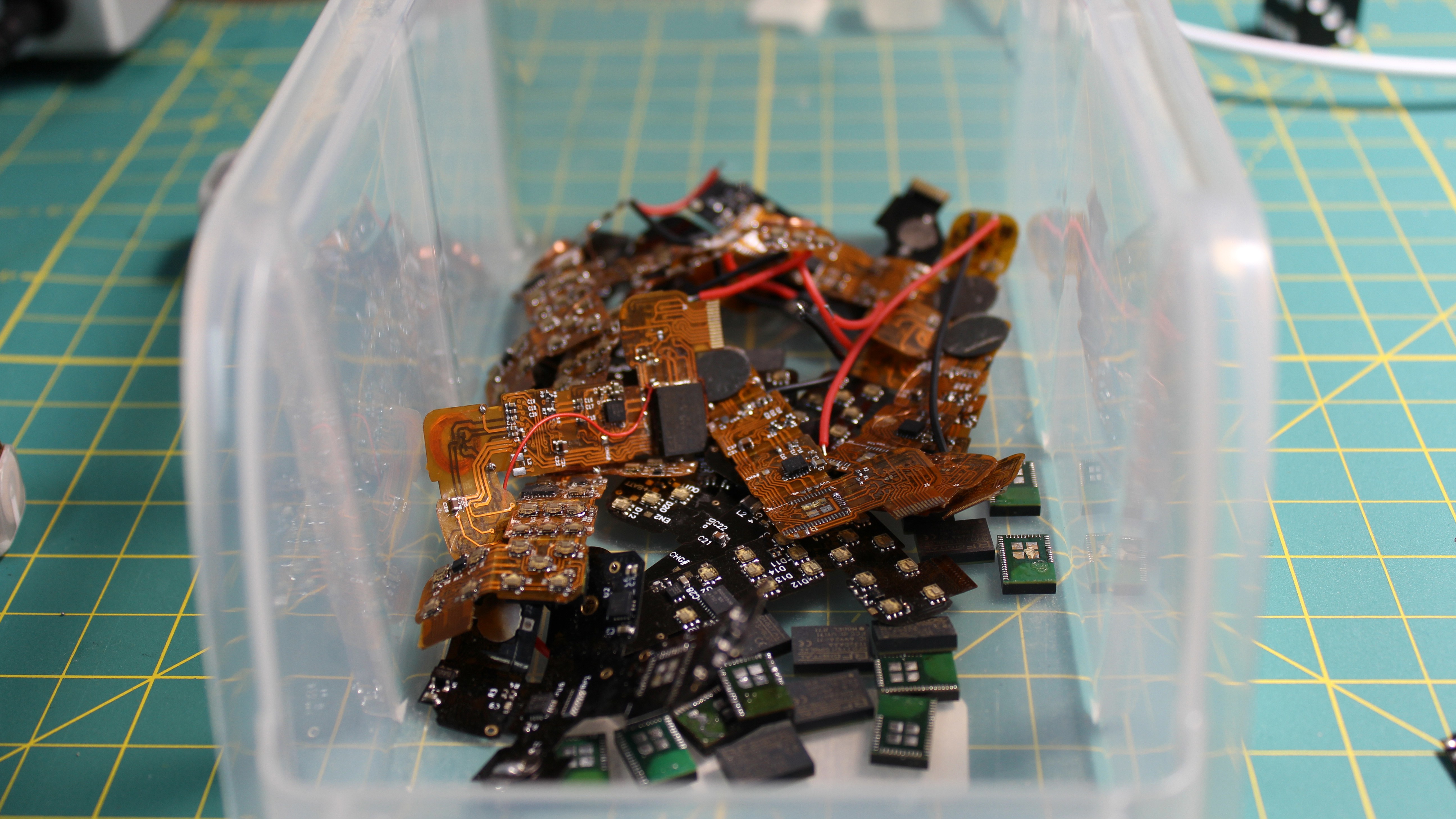
New boards
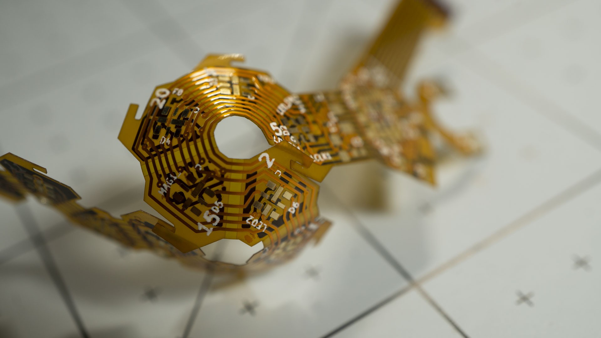
I think I've lost track of the number of board revisions, but new D20 boards just arrived as I write this. I ordered them in all the colors that PCBWay offered, as I want to see how the color of the board affects the final look of transparent dice.
---------- more ----------
The BOM is pretty much the same as previously, the main changes are minor functionality-wise, but important for manufacturing and end use. Let me go through them!
Proper outline
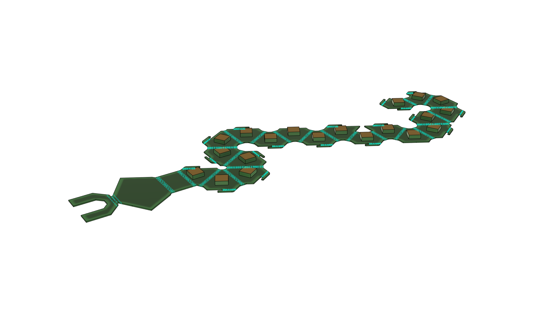
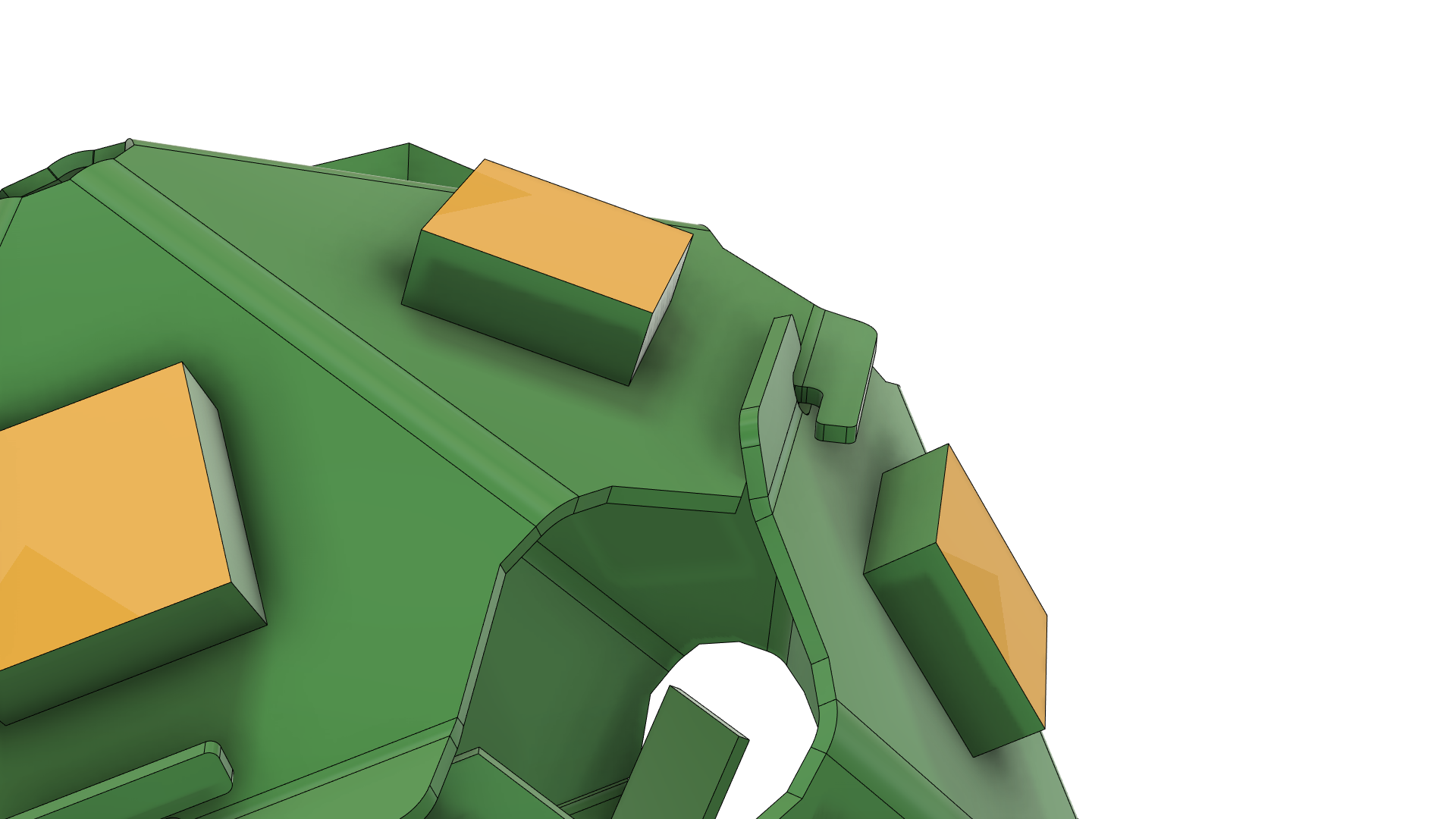
The previous version of the fold-able board didn't perfectly line up once folded. It was pretty close, but not exactly right. So this time I took the time to really model it in Fusion 360. The "Sheet Metal" tool is really great for this. I created a custom material with a 0.2mm thickness (the PCB thickness) and 0.0 K factor (K factor is a representation of how much a given material stretches when you try to bend it) and designed the folding pattern one face at a time, making sure that everything fit together every step of the way.
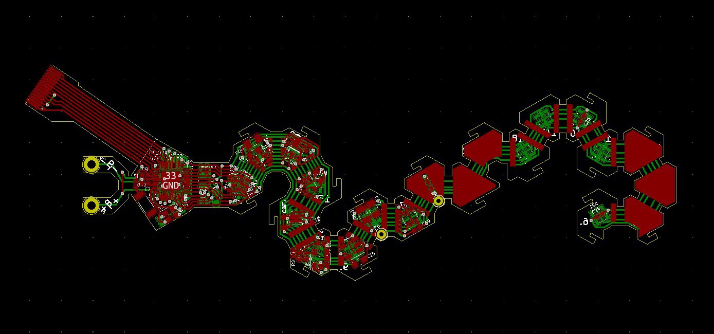
Once I had the outline properly figured out, I exported it to Kicad to use as a board outline and started re-routing the board. Once again, I added small areas of metal and solder paste to stiffen the board on each side of a bend. This has worked really well in the past to make the board naturally bend into shape without needing to be preformed.
Of course the new outline features the interlocking notches I mentioned in the previous update. Fingers crossed that they function exactly as intended and reduce the folding/assembly time drastically.
Lastly, the new outline features specific cut-outs on certain faces. This is again targeted at manufacturing. Those cutouts will match registration pins inside the molds, so that a folded circuit board can only be inserted in the molds in a specific way. This is important because otherwise the numbers on the faces may not match what the microcontroller thinks they are. The presence of the coil was already providing some registration, but it still allowed a certain rotational symmetry, meaning that it was possible for the 1 and 20 to be correct but not the other faces; a huge pain in the rear for 'calibration'.
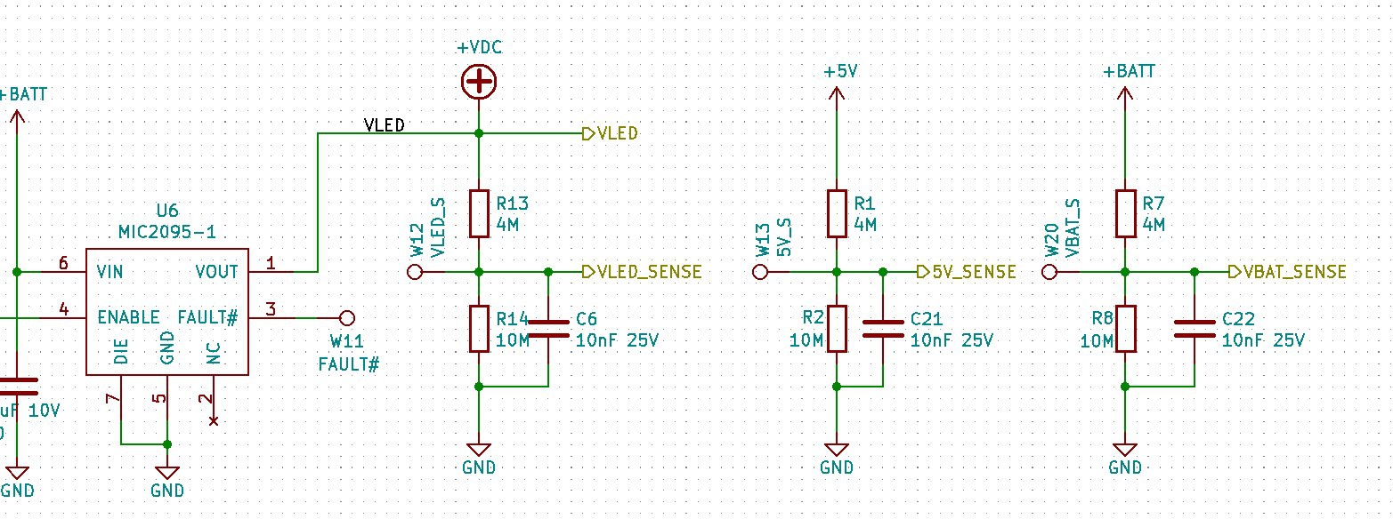
More voltage monitoring
I updated the schematic a tiny bit to use a couple more A2D pins to monitor the charging and LED voltages. This won't be super useful during use but will make testing boards during manufacturing that much better. The board will be able to quickly check if there is something wrong with the LEDs and/or charging circuitry, hopefully leading to a faster test on the assembly line.
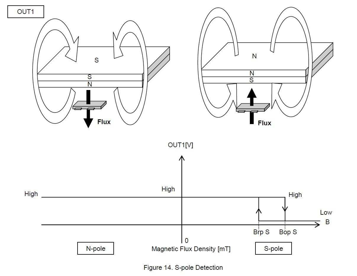
Dual monopolar Hall-effect sensor
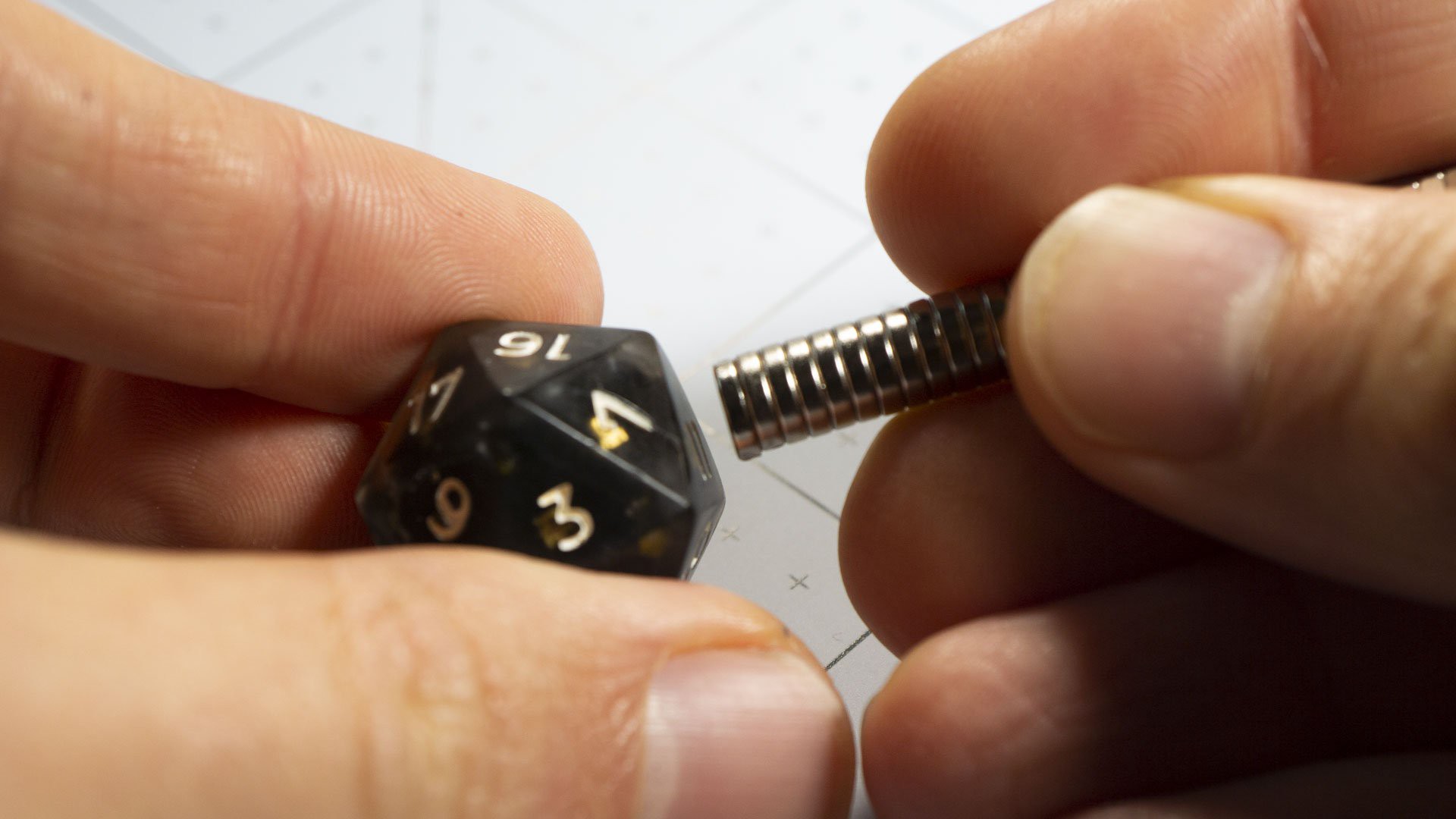
You read that right, it means the sensor has two elements, each only sensitive to a single pole north for one, south for the other. This is in contrast to an omnipolar sensor, which would have a single element, sensitive to either pole. Previously I was only using the north pole output, and had it connected to the voltage regulator enable pin, so that I could easily power-cycle the microcontroller (a crititcal feature during development). I was also planning on using that magnet to power down the board during transport - each charging case would have a small magnet in it - so that the dice doesn't drain its battery for no reason while being shaken, and that is working great.
However, I have started designing the 'To Go' case. This is a case that can charge 8 dice at a time, and has a battery of its own so that it can recharge the dice without itself needing to be plugged in. That's great, but being on battery itself means that this To Go case needs to be smart and only charge the dice when necessary, stopping when the dice are full. Otherwise it would keep driving the charging coils forever and drain its own battery. This meant that some form of communication was necessary between the case and the dice. The Qi standard has a fairly complicated way of doing this by modulating the load capacitance, and I didn't want to go down that route. In fact in the previous log I explain a bit how I started using Qi but then moved away from it.
Anyway, I eventually decided to just have the case talk to the dice using the existing Bluetooth :) This meant that I couldn't have the dice simply turn off while they were charging in the case. So I hooked up the south-pole output of the hall-effect sensor to an interrupt pin on the micro. This way, the charging case can have magnets embedded in it such that the south pole triggers the hall-effect sensor and essentially "tells" the dice that it is inside the case and that it can go into an extremely-low power mode, waking up as necessary to communicate, while still being able to use the north pole of a magnet to reset the micro-controller!
And finally, the last change was to move the hall-effect sensor to the 20-face of of the dice. Since the charging coil is on the 1 face, it means that when a die is placed in its charger (with face 1 down) the sensor is in the right spot to be triggered by a magnet inside the top cover of the charger, regardless of how rotated the die is inside the charger. This is one of those completely-obivous things in hindsight, but that you don't really appreciate until you've started actually handling and using your product.
Material testing
I think I've mentioned previously how I wanted to try different combinations of material for the dice, and this is also going on as I write. I had many many questions:
What type of clear resin would give the best results?
Is semi-clear better?
Can the interplay of clear and opaque resin create cool effects?
Are additives (mica powder, titanium dioxide, etc...) enough to create an opaque resin, or should I use a different resin to begin with?
Would adding glitter flakes improve the diffusion maybe?
What about non-neutral colors? Can a midnight-blue die look cool?
etc...
I needed to run a lot of experiments. The thing is: I didn't really want to sacrifice a pcb for every single try, I don't have that many...
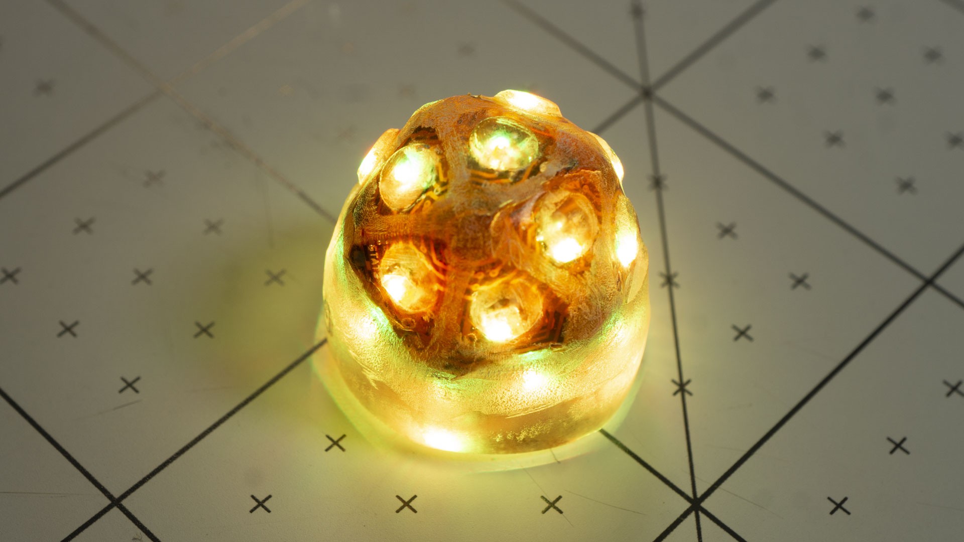
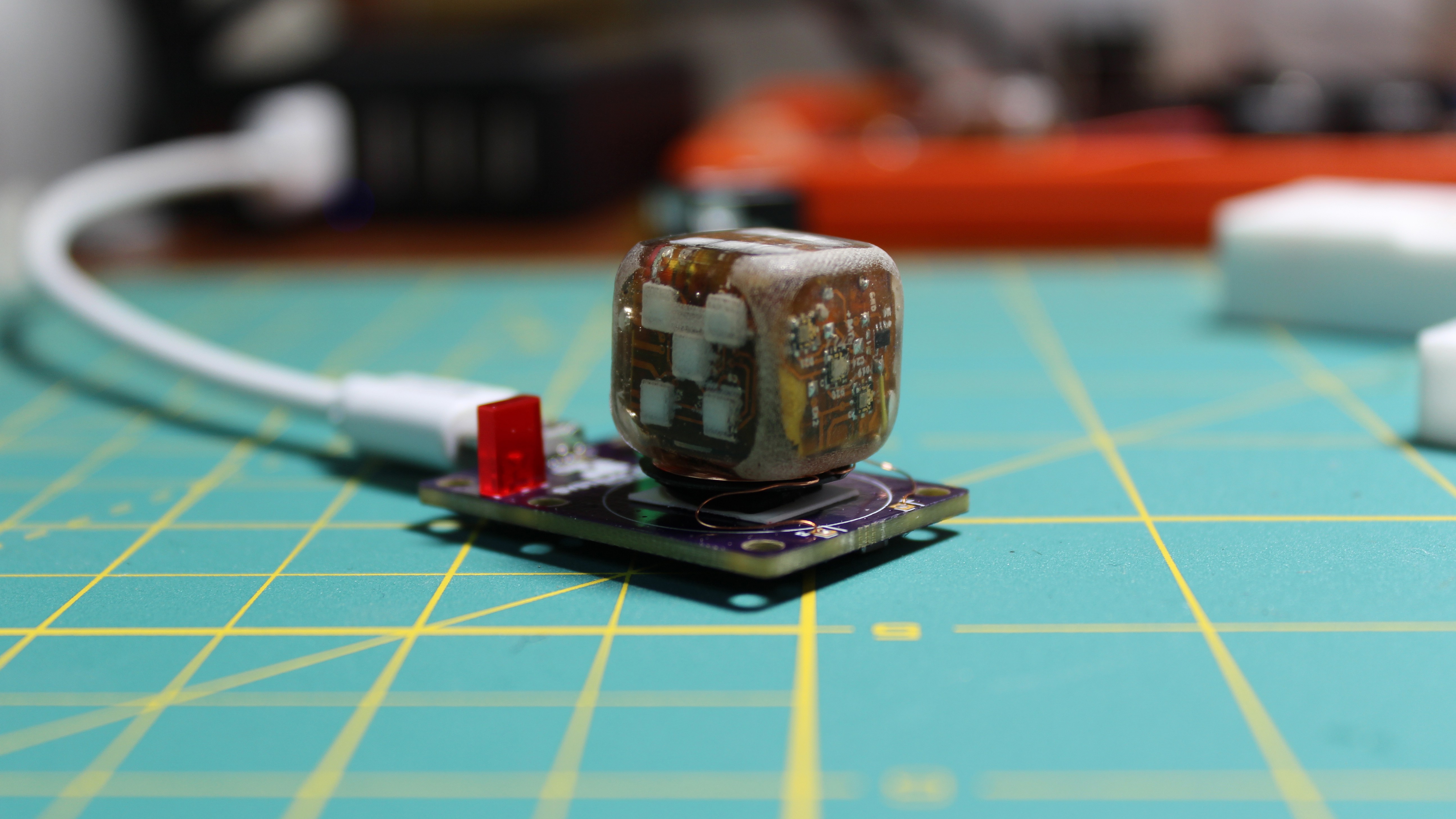
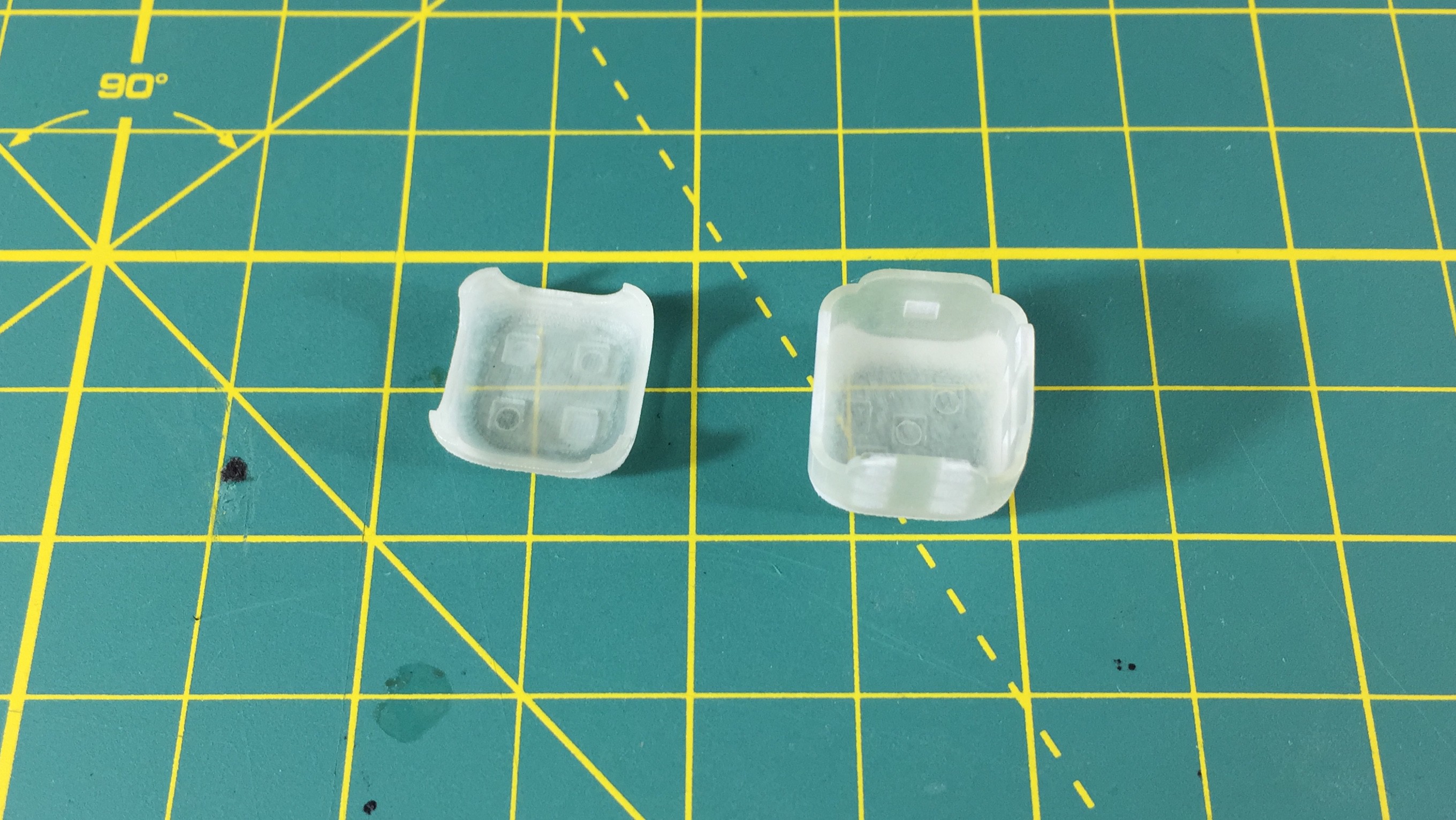
So instead I made a little "Core"; essentially I poured resin around a folded pcb so that it would be protected, but kept it as thin as I could. Then I created molds for hollow half dice, like little caps I could snap on top of the core to see how the light would shine through! These half-dice caps are still cast in two steps (see previous updates), giving me a chance to try clear/opaque resin combinations, as well as different designs, without wasting pcbs.
I have only made a few castings so far, but I have already learned a number of very interesting things:
The first is that liquid additives (for instance the Pinata alcohol-based ones) tend to mix more uniformly than powder-based. Take this with an asterisk though, because it may entirely be my fault, not so much the additive's.
The second is that making a really thin layer (1mm) of transparent resin opaque takes a lot more additive than you think. In fact I got much better results starting with a different kind of resin altogether. Using additives caused the light to 'bleed' through thinner parts of the casting in unpleasant ways.
Then glitter / mica powders don't really interact much with the LED light. I bet there are really interesting reasons why (involving the single wavelength spectrum of LEDs and the microstructure of glitter kind of thing...) but the bottom line is that those really are only useful for improving the look of the dice when NOT lit up. Also, another one of those obvious-in-hindsight things: if you mix glitter in your opaque resin to try and have a glittery surface finish, you need to mix A LOT of glitter in, because most of it will be wasted under the surface. What I have seen dice makers do instead is brush the glitter on the inside of the mold before casting in resin. I haven't tried yet...
But the most important thing I learned what the difference between Urethane-based resin and Epoxy-based resin. It's not always clear which one you're using, but it matters. The end product looks and feel the same, in clear or opaque. Urethane resins are often thinner than Epoxy resins, but that it not by nature: it's just that a lot of Epoxy resins are "Art" resins or counter-top resin and are therefore formulated to be thicker and have longer pot-life (to give you more time to work with it). But you can actually make thick Urethane resin or thin Epoxy resin. Smooth-on, for instance, sells all variations of both. No the main difference, besides the smell, is that Urethane resin gets softer with heat. Epoxy resins doesn't.
I realized this when I tried to recharge my little led core with a Urethane resin cap on: the cap got all soft on me! The core had warmed up to maybe 50 degrees C from the charging and the cap was completely squishable. This is not something I really want for the final dice. Note though that it hardened right back after cooling down, and it didn't seem deformed at all, but still...
So far I have had some success with material combinations. For opaque dice, I've found that an inner layer of just slightly tinted black transparent epoxy and an outer layer of neutral opaque epoxy looks really good! Surprisingly, a totally black outer layer doesn't look as good, and I can't figure out why... It's fascinating and I can't wait to try more stuff!
I have a few more types of resin on order for even more experiments. I am really excited to try the aluminium-filled one; first to see if it is significantly denser than the regular stuff, and then to see if it's possible to get a polished finish on it... would love to be able to create burning-metal dice :)
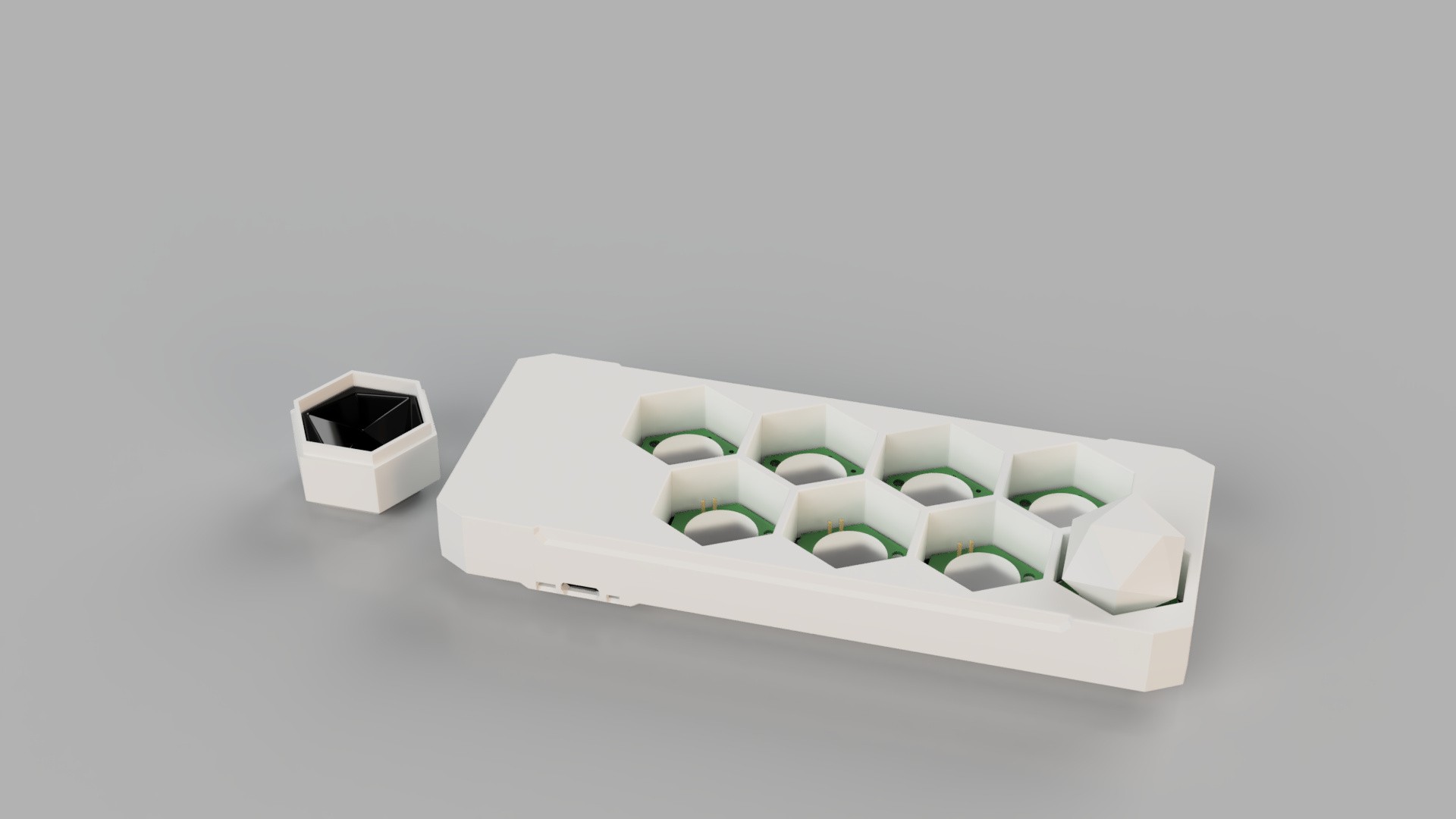
Chargers
I have also spent some time designing chargers for the dice, and that in itself is another interesting story!
I need to distribute a charger for each die that I sell, obviously. This means that the cost of manufacturing the charger is, for all intents and purposes, part of the cost of a die. That cost must be as low as possible. The coils are so small that in order to couple properly, they need to be really well aligned between the charger and the die. This means, in essence, that each die requires a custom charger, or more specifically, a custom cup that it will sit in to get recharged.
On the other hand, most people will buy more than one die (hopefully many more) and having to juggle 6 or 8 individual chargers does not sound like fun. So I want to offer a multi-die charger, the To-Go charger I mentioned earlier. But of course, players may not necessarily all want to purchase the exact same set. Maybe one player wants to get eight D10, or six D6, etc... In short I can't make a one-size fits-all multi-dice charger. And of course, if you buy the To-Go charger, then you've overpaid for the dice and now have a bunch of individual chargers you don't need anymore. A huge waste!
It would also be a SKU nightmare! "Do you want to get the 'midnight black set with 2 D6s' or the 'clear set with 8 D10'?", "Don't forget to add a single-die charger if you didn't get the To-Go case!" etc...
So I came up with something that I *think* will work; it's a bit of a gamble though.
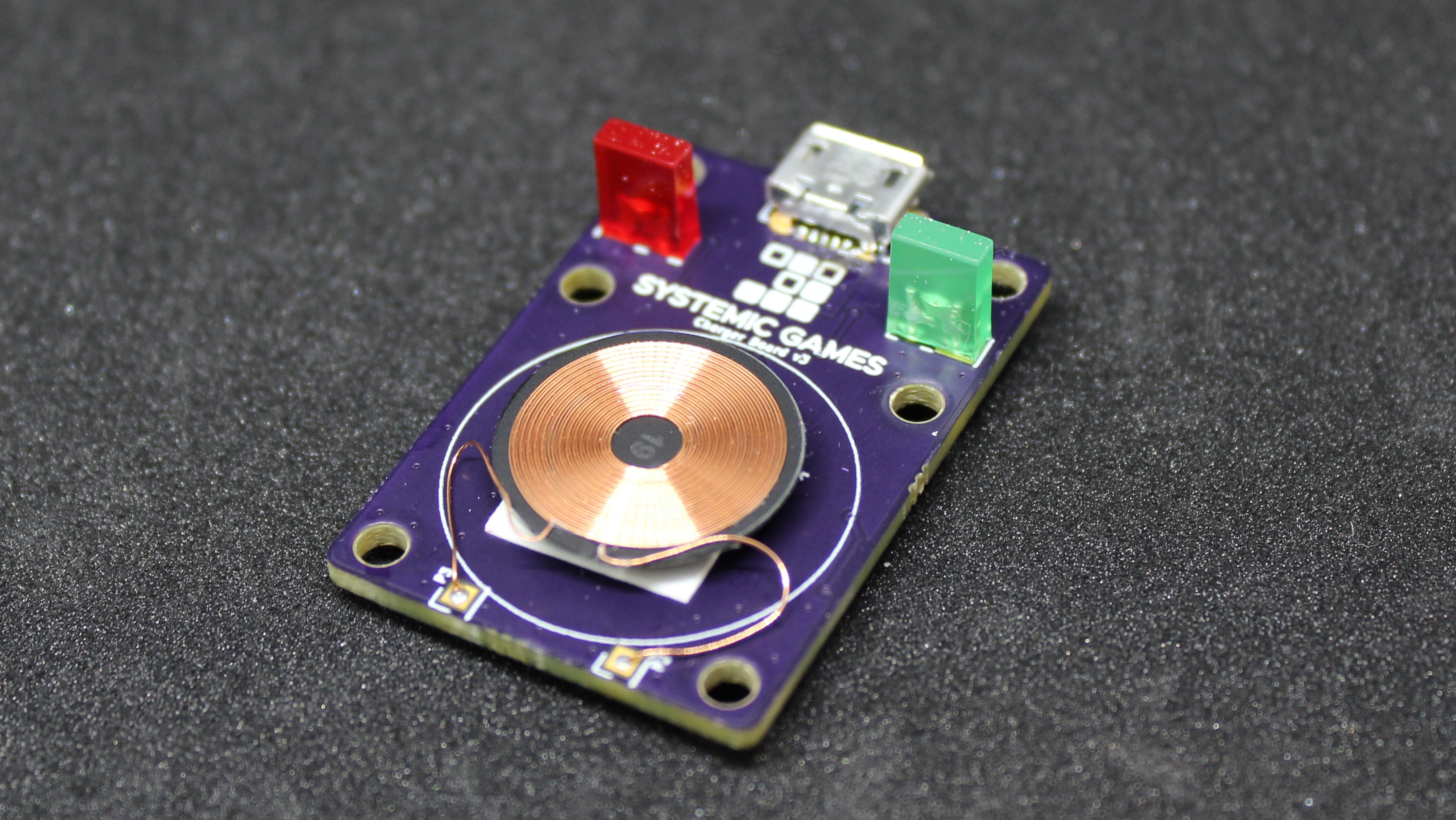
First off, each die you buy will come with a charging case. There is no way around it. You can't buy a die without a charger. The case, off course is important anyway because it allow you to "turn the die off" while you're transporting it. The charging circuitry is still based on the XKT-412 and XKT-335, super dumb but super cheap. When you need to charge the die you can plug it in to a usb plug and you're good to go. I'll only include a micro USB cable, no wall-wart. A lot of cheap electronic devices do this and nobody seems to mind.
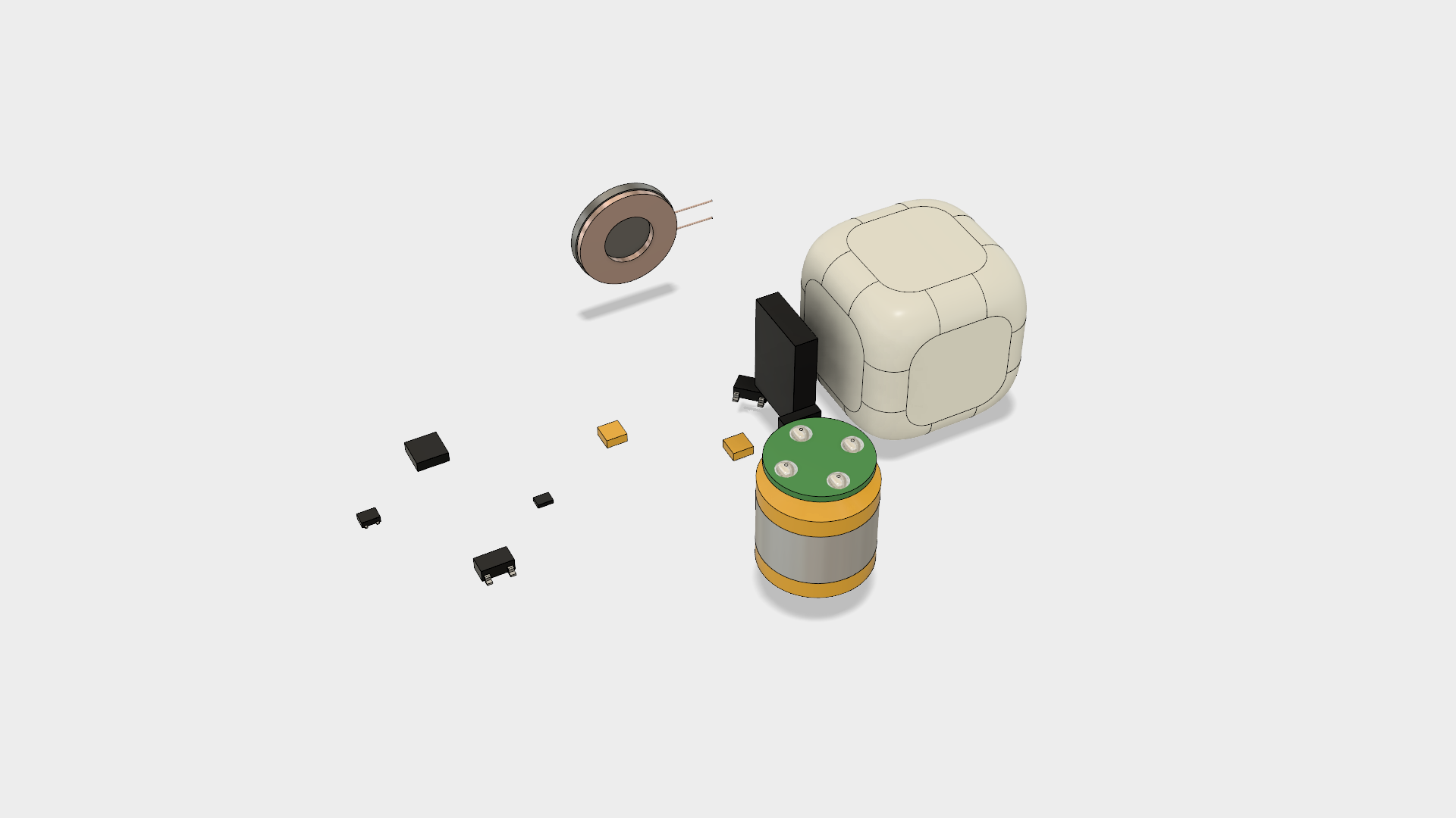
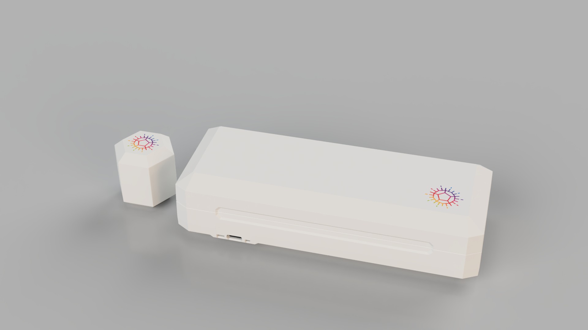
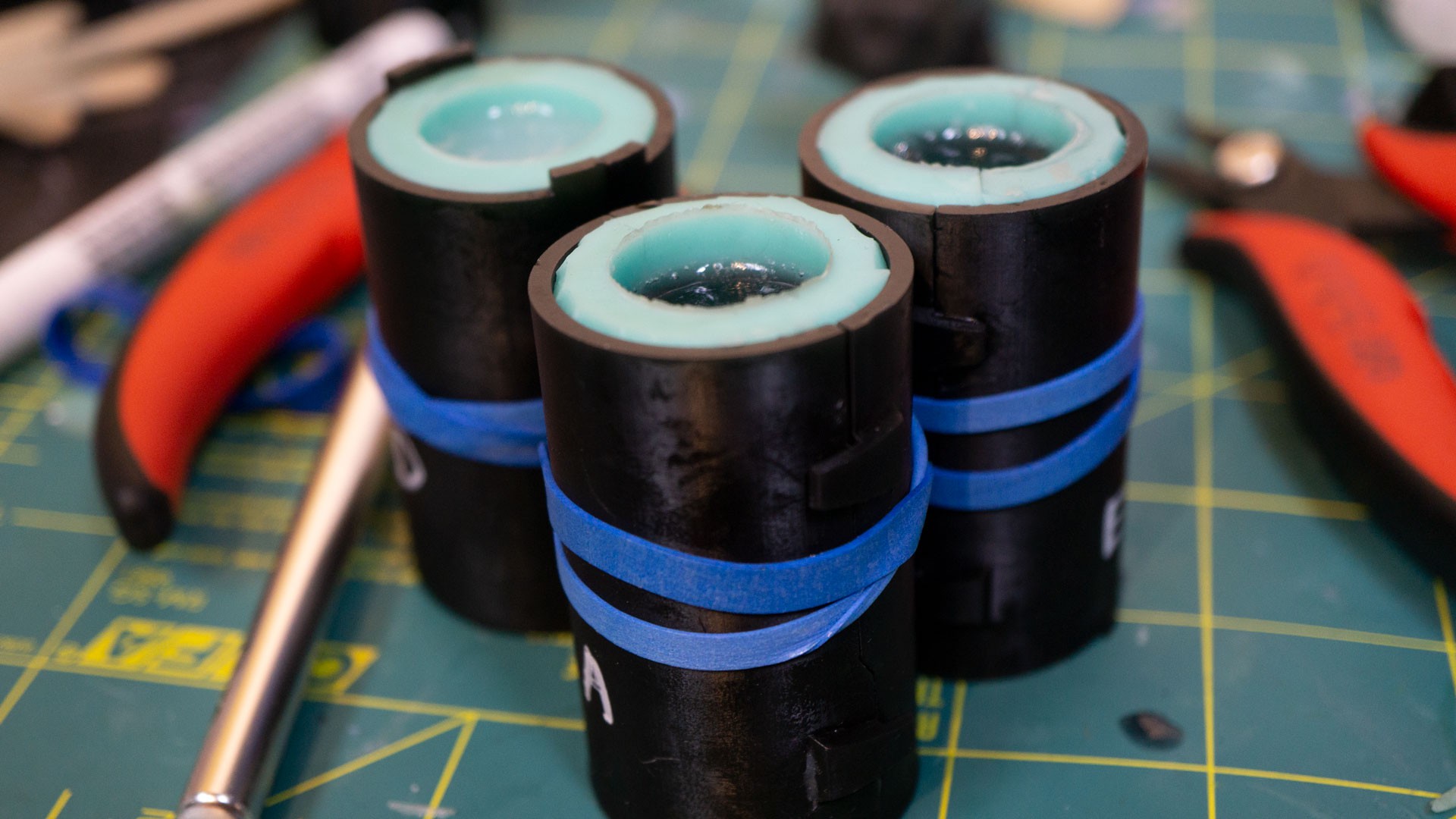
However, this simple charger will be built in a way that it can easily be taken appart, and that's the gamble! There are only 4 parts to it:
The top lid
The bottom base
The Coil PCB
A vacuformed insert
Only the insert is specific to the die that the charger is sold with, the rest of the components are common to all chargers. This is already a benefit in terms of manufacturing costs. The insert will have to be vacuformed for the simple reason that it needs to be really thin (0.5mm) and that seems too thin for injection molding.
To-Go chargers will come without inserts and receptacles to plug in the coil PCBs directly. So in order to make your To-Go case functional, you'll have to plug in the Coil PCBs and add the inserts yourself. This will give you the greatest flexibility in how you want to organize your dice, while reducing both the cost and combinatorial complexity of offering a million different versions of the chargers.
I could make it that you only need to add the inserts yourself (i.e. the To-Go charger already has Coils for each die) but the Coils ARE the most expensive component of the charger, so... it may be worth it. I don't know, I may still change my mind. :)
In any case that the jest of it. I am hopeful that rather than put people off ("Oh no I have to assemble this thing myself...") it will make it feel more personal, customized. We'll have to wait and see...
I put together a short video of how I assemble a die, for anyone who's interested!
Here are the steps shown in the video, and some notes to go along:
---------- more ----------
1. Receive boards (and components) from PCB factory
Soldering components on double side flexible PCBs is a real pain! For the previous version of the dice, I did it all myself, and it was dreadful. This time around though, I had the PCB factory (PCBWay in this case) do it for me. I'm pretty sure that they also did it by hand, but they are obviously much more skilled than I am. :)
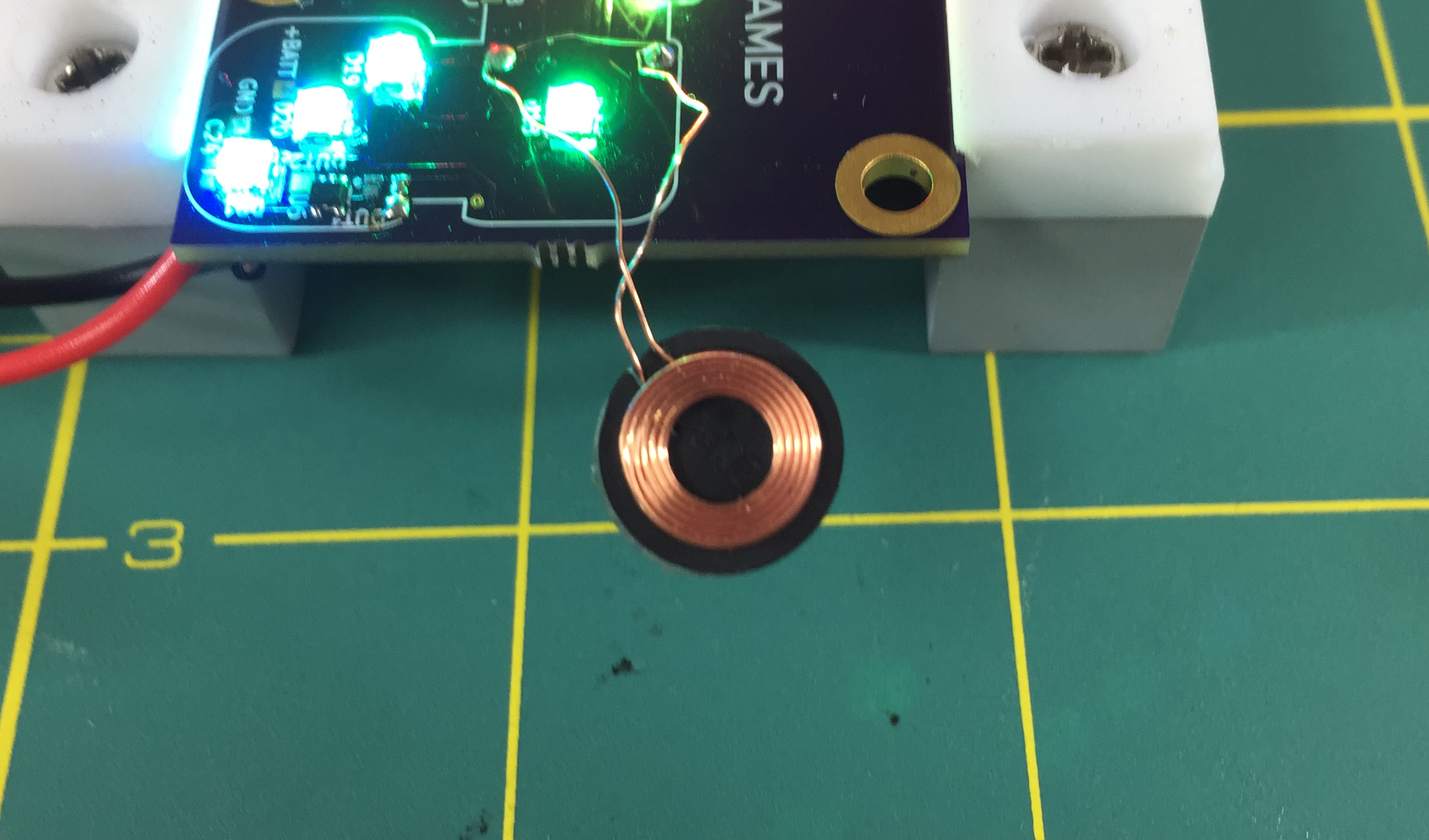
2. Solder Charging coil
A step I didn't show in the video is that I also needed to prepare the coil leads and remove most of the enamel before soldering. My hope is that for large quantities, I'll be able to order coils with the lead lengths that I need and not have to strip or maybe even cut off the extras.
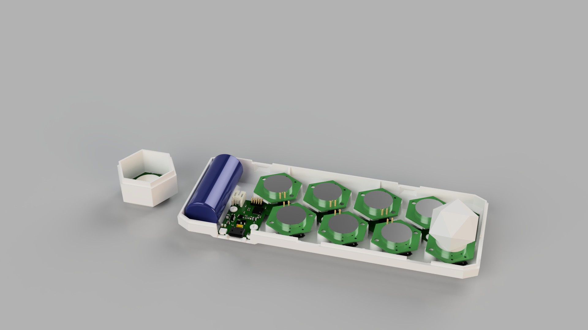
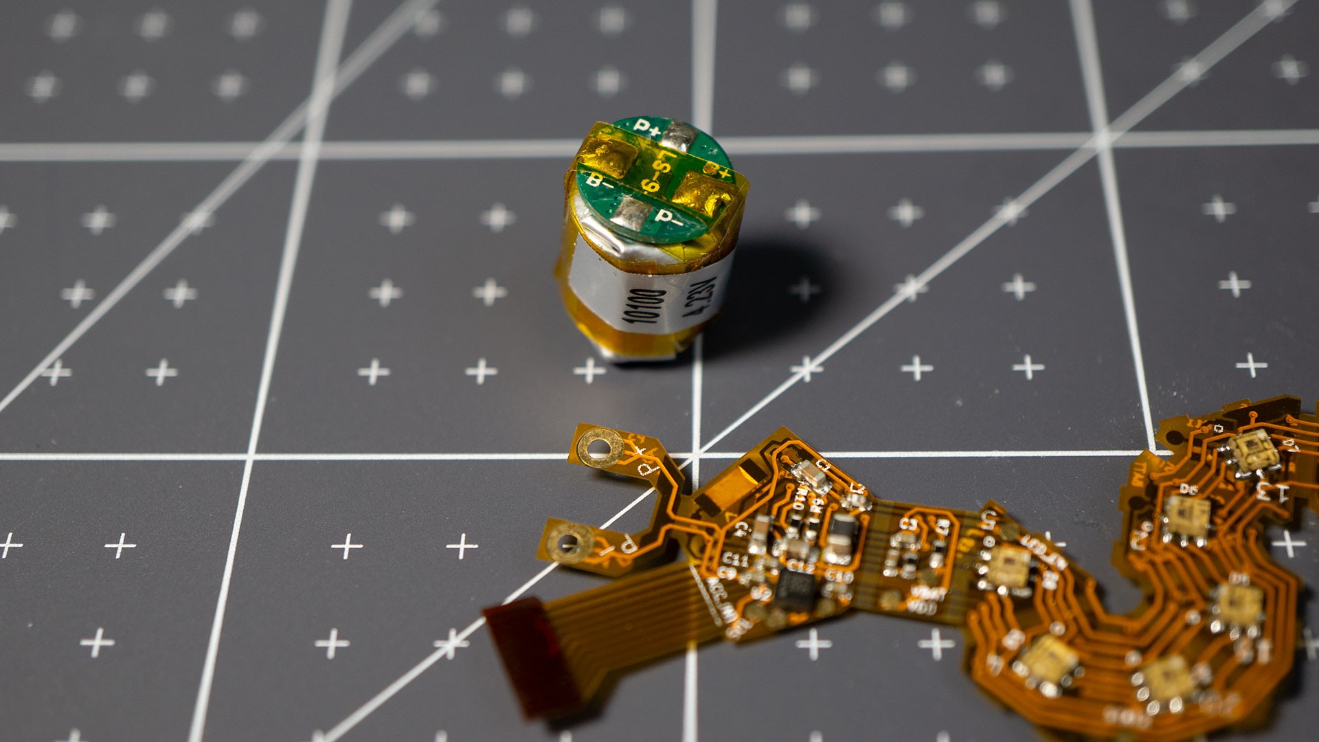
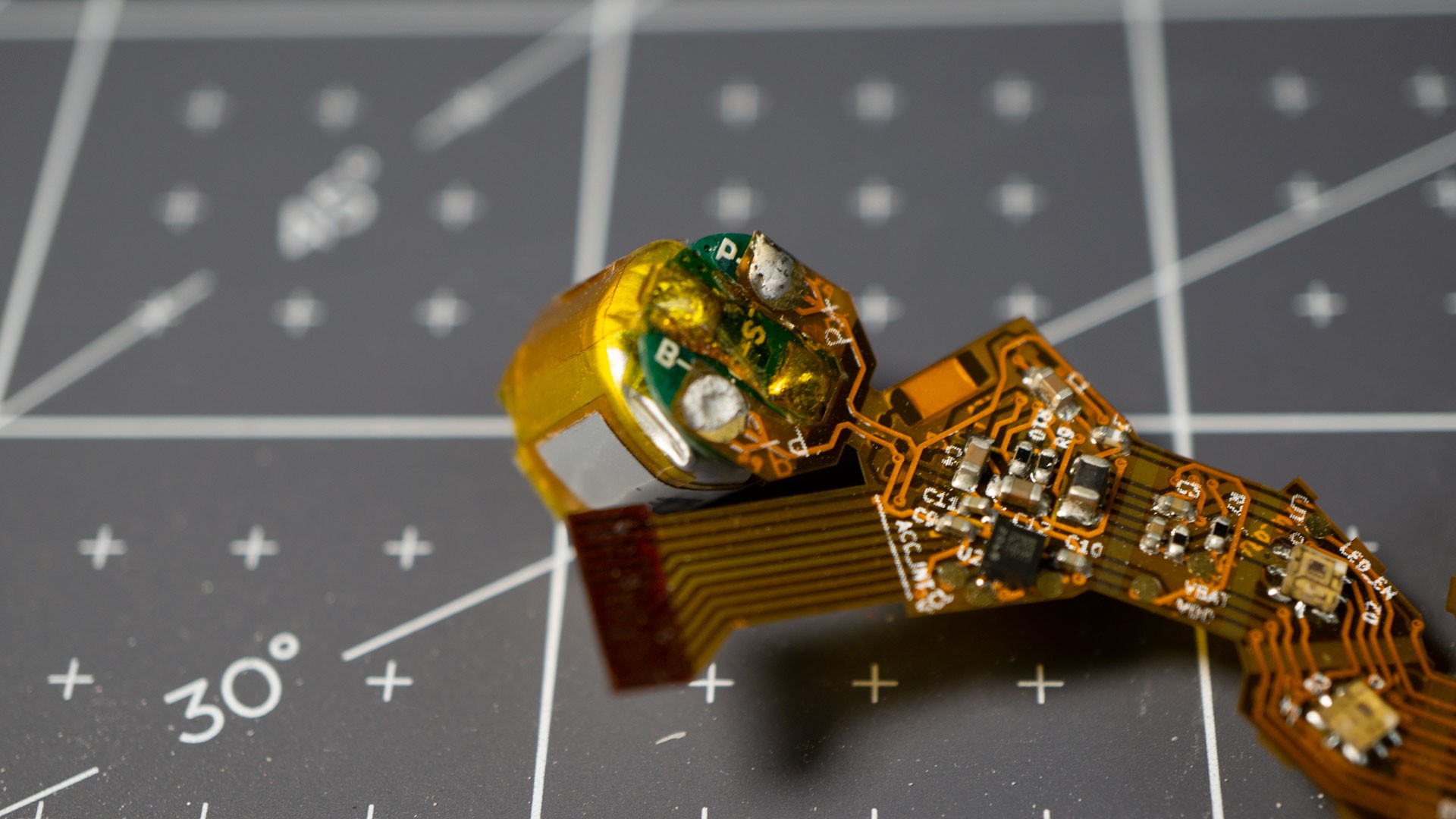
3. Solder Battery
I'm pretty proud of this one: up until recently, I had wires connecting the battery to the PCB, because, well, that's what you do, right? Only I finally realized that I could shape the flex PCB just right so that I could solder the battery directly to the flex circuit, saving a ton of time, and a little bit of material (the wires).
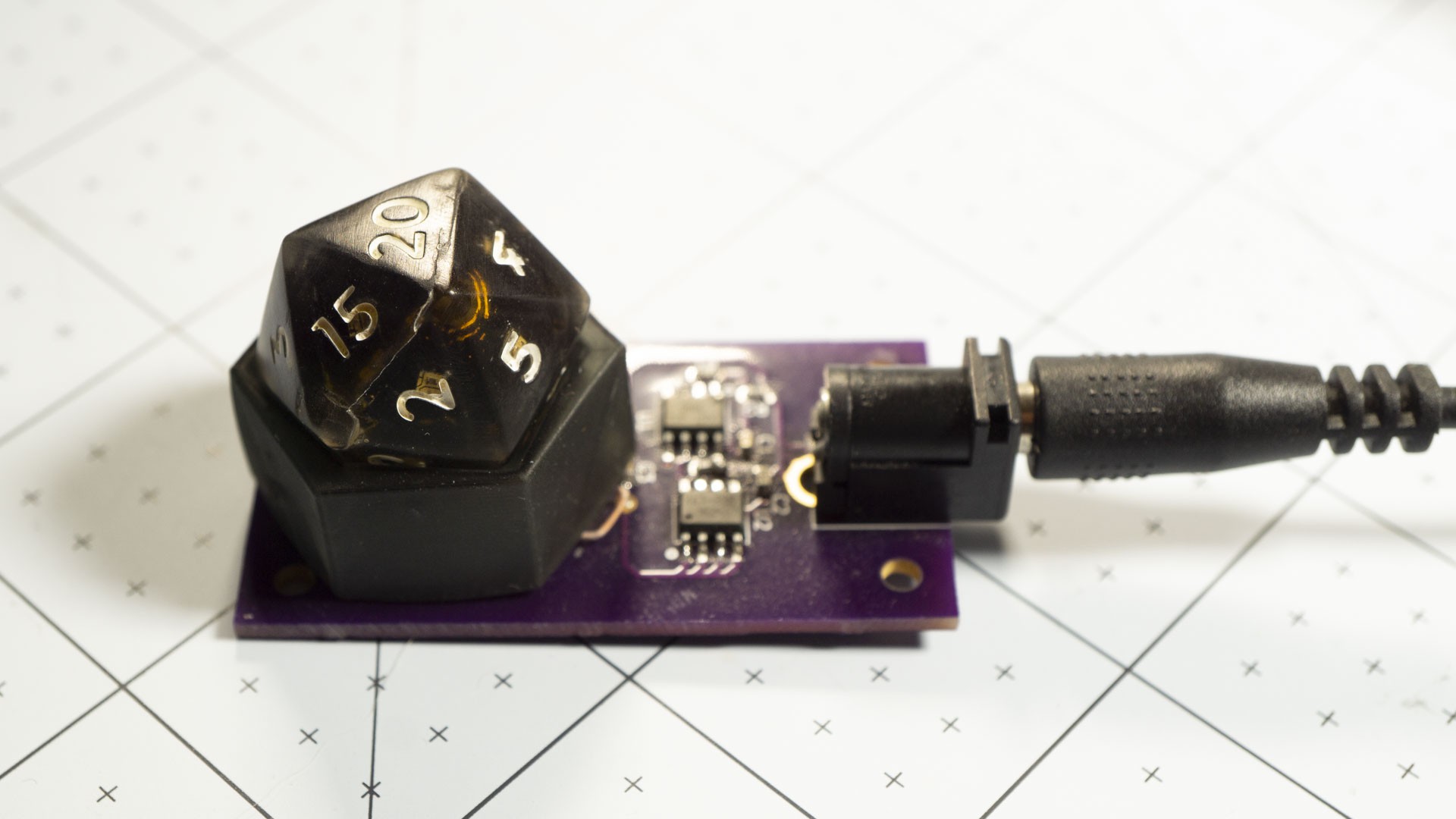
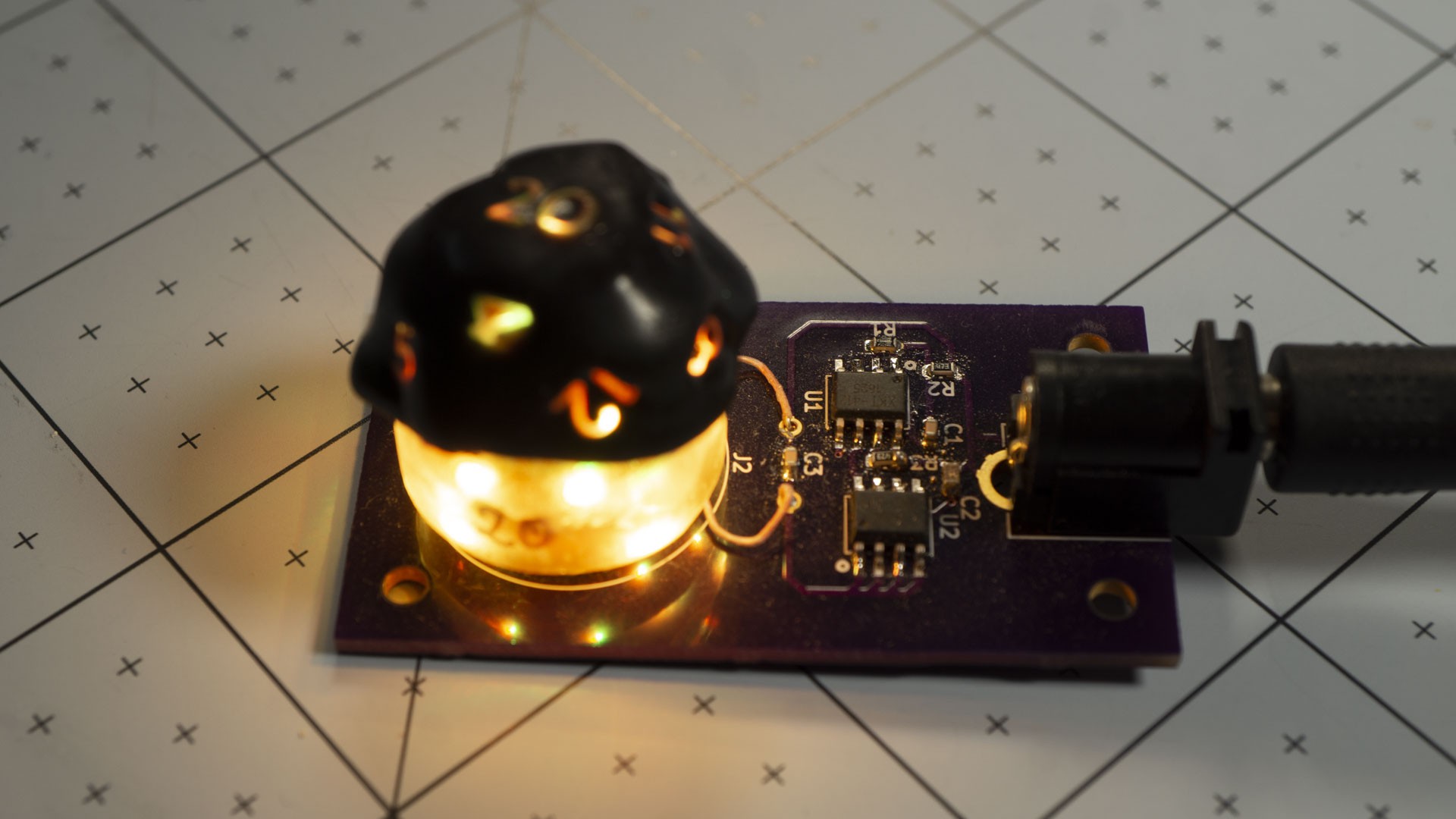
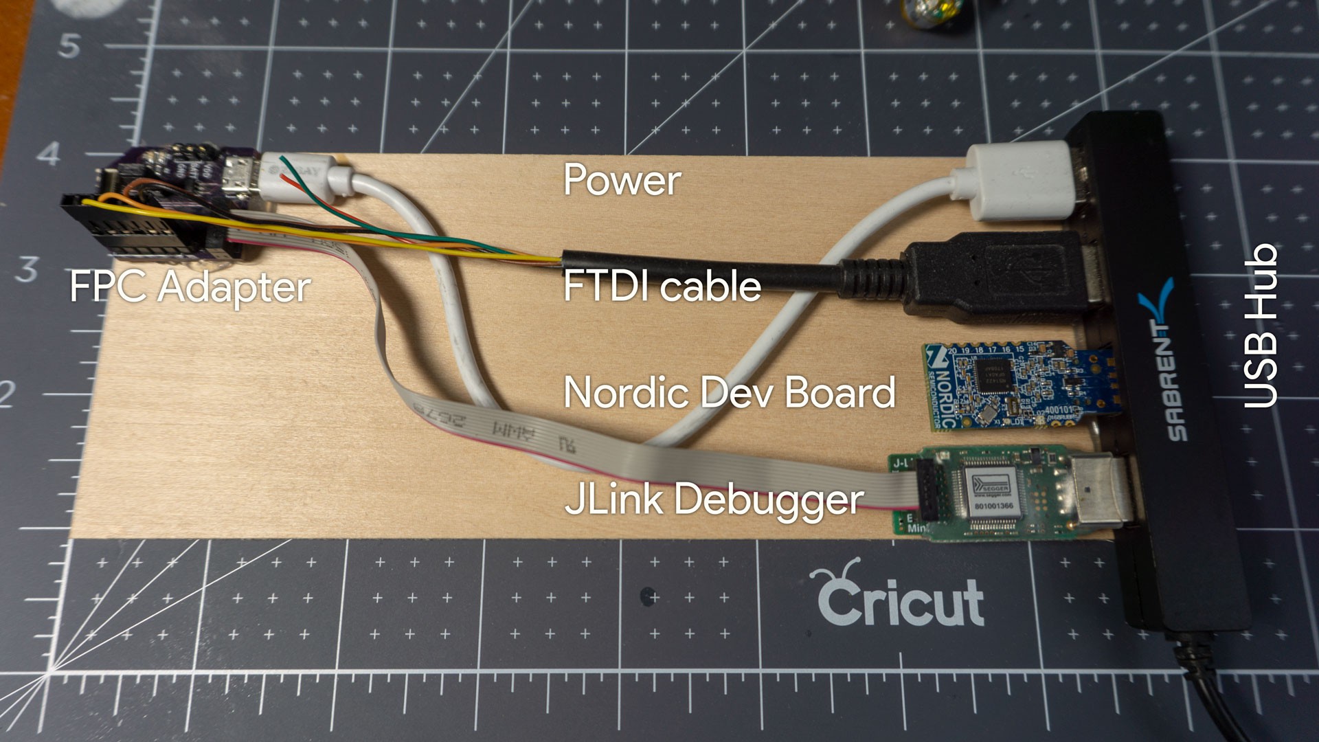
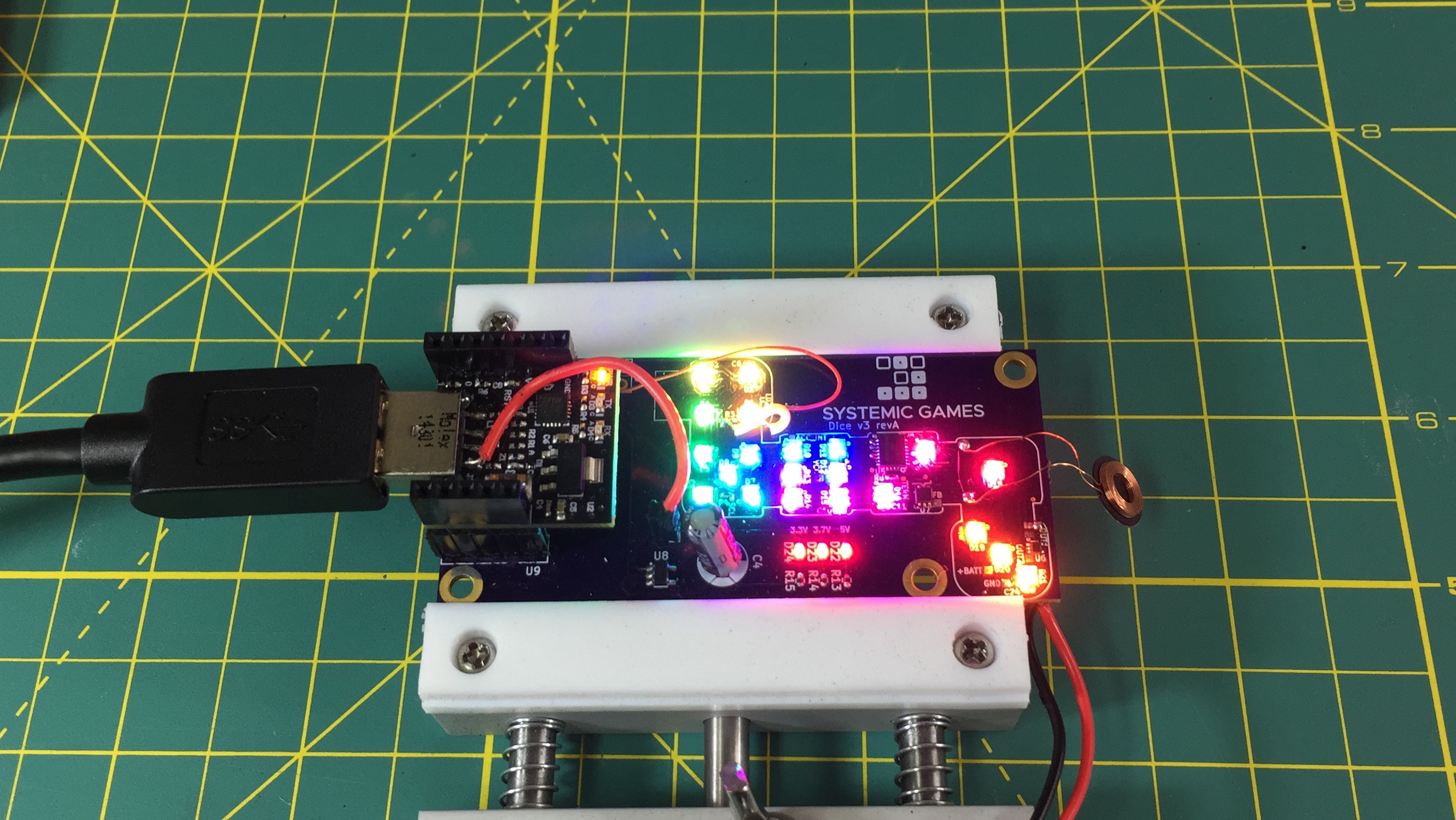
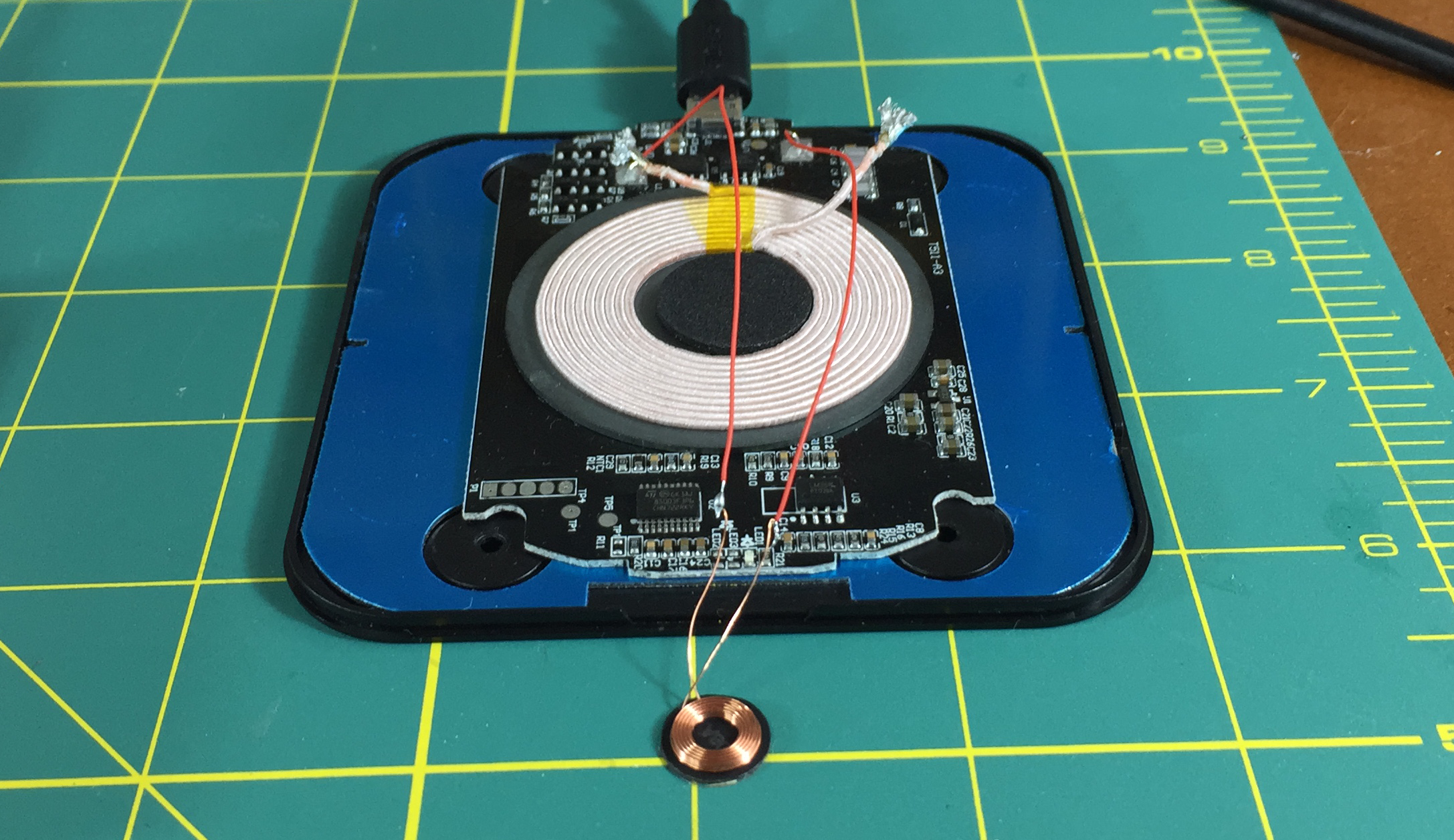
4. Program and Test
Plug the board in, program the bootloader, run some tests, make sure the LEDs light up, etc...
I imagine that in a production setting, this will be a lot more involved. I think I will end up using a standalone Raspberry Pi that can take care of everything at the press of a button, no HMD needed. It'll be fun to build!
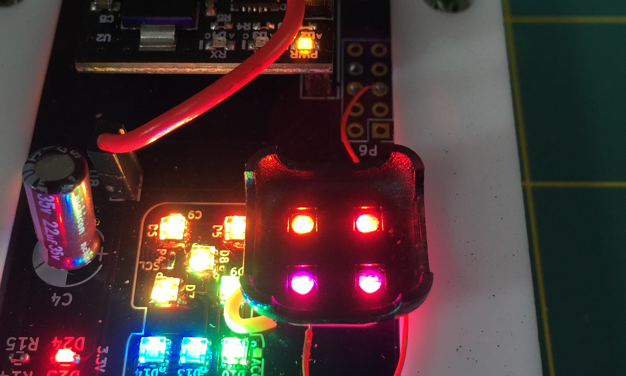
Right now, this is my setup:
5. Paint / Clear coat
While I am experimenting with colors and materials, I use this step to change the color of the PCB (to white in the video). Once I have settled on what color(s) to use, I'll just get the PCBs made with *those* color solder masks. However, the coat of paint actually serve a secondary purpose, and that is to cover the exposed metal contacts (for instance on the battery) ahead of the next step, the folding. Initially I placed a strip of Kapton tape over the battery, but I think a couple layers of clear coats will be just enough. The intent is to prevent shorts during the folding, the coating doesn't need to be resistant. Once the resin gets poured everything will stay in place!
6. Fold and Glue
This is right now the longest step and the one I am trying to improve. Mainly the issue is that I have to wait for the glue to dry :) over and over.
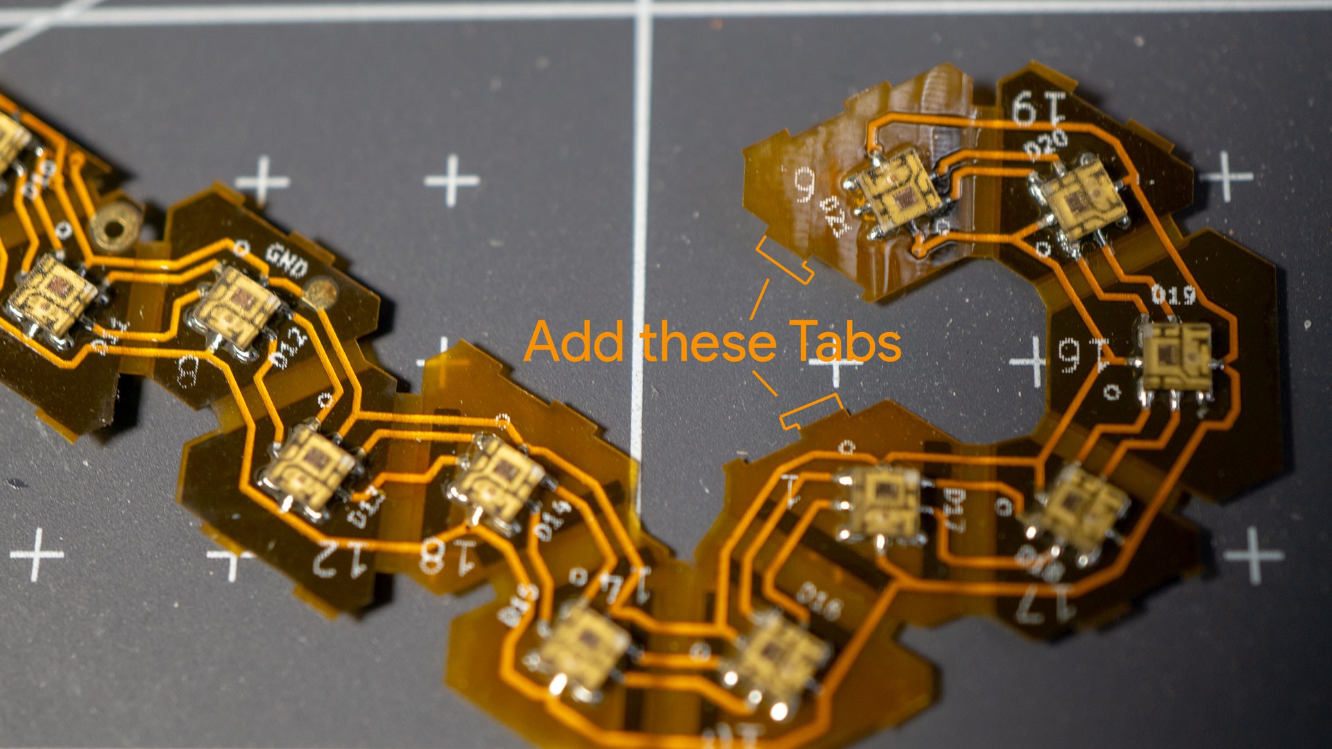
I had tried adding little 'solder tabs' to the edges, thinking I could use get the edges to stick together with a little touch of heat, but the solder wouldn't bridge. Eventually the tabs came off the flex substrate, probably from the repeated heating of me trying to get the solder to wick.
I am thinking of redesigning the PCBs to have some sort of hooks on the edges, so that they can latch together as I fold them:
I already have registration tabs, but with the hooks, I'd only need to add a bit of glue once the whole thing is folded. They would hold together long enough to fold the whole thing up.
We'll have to see, I have a few more things I need to tweak on the PCB design before the next revision anyway...
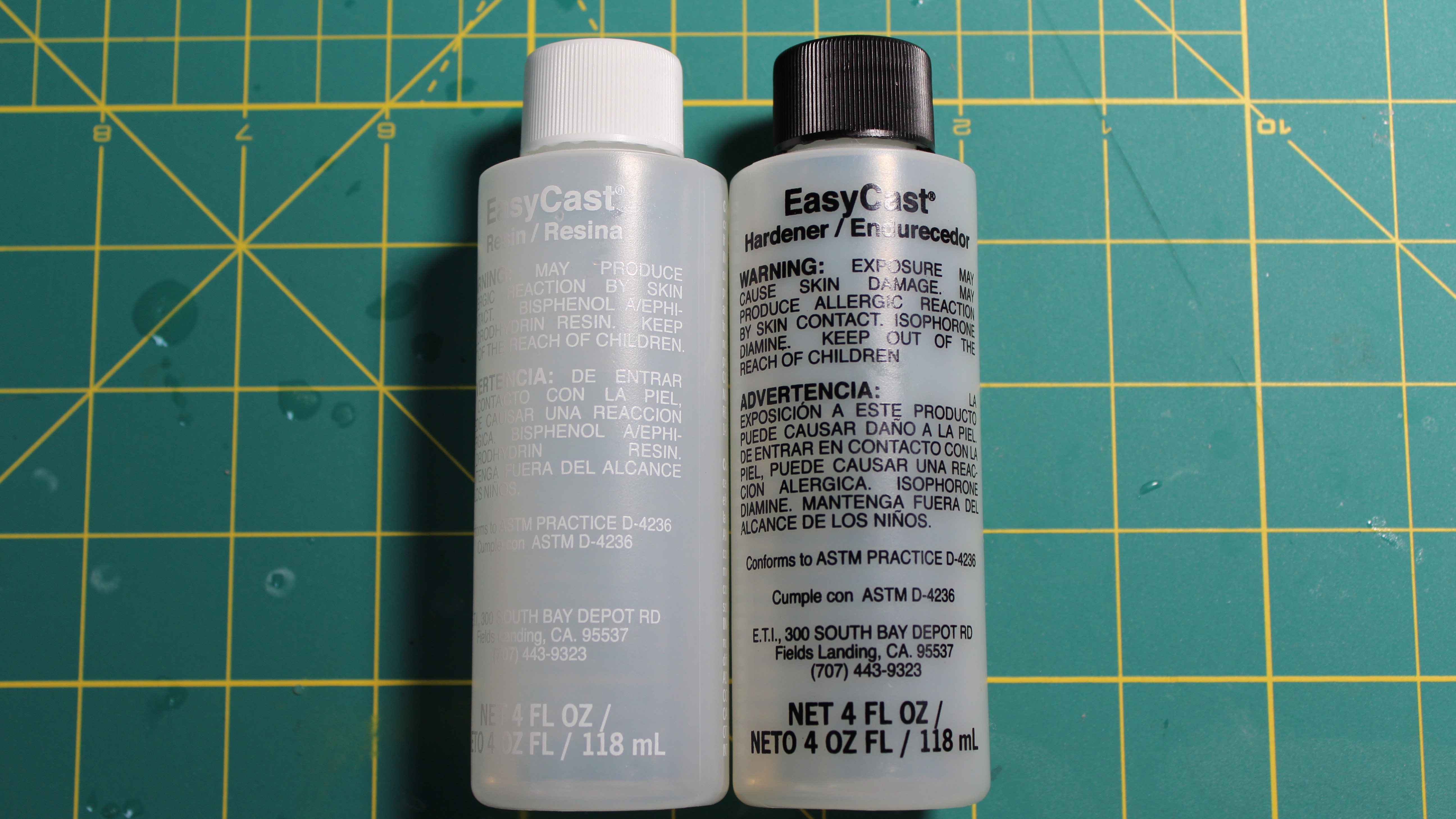
7. Prepare Molds and Resin
For the resin, I am using Total Boat, although I have used ArtResin as well. The main property I am looking for is a resin that cures very slowly and hard so that I can try and get the clearest resin as possible.
One of the big thing I am still trying to figure out with the resin is how to add texture without rendering the resin completely opaque to the LED light. I think the two-step process can actually help a lot here, for instance by having a clear first layer and then a more opaque (i.e. diffusing) second layer. Also white resin obviously diffuses better than black, but I really want to have some black dice :)
Anyway, ideas welcome!
8. Place PCB inside mold
The most difficult part right here is to align the PCB correctly. I think I need to add a registration 'pin' to the mold, so that the folded PCB can nestle perfectly in the right spot.
Unfortunately, I'm not quite ready to make more PCBs to have the matching registrations, so for now I just need to take my time, but I think that's something I'll be able to solve for production. Again, the less chances to mess up and the quicker I can make each step, the less it'll cost me! ;)
9. Pour resin
I really need to try and see if I can modify the molds so as to not need the vacuum chamber. Right now the clearances are so tight that the resin doesn't always flow everywhere unless I do that. It does get better with the pressure pot curing, but sometimes it still leaves small bubbles.
10. Cure under pressure
This is the main way to get a good finish! You can see I use a small compressor and a modified paint pressure pot. There are tons of tutorials online if you're interested in building your own too.
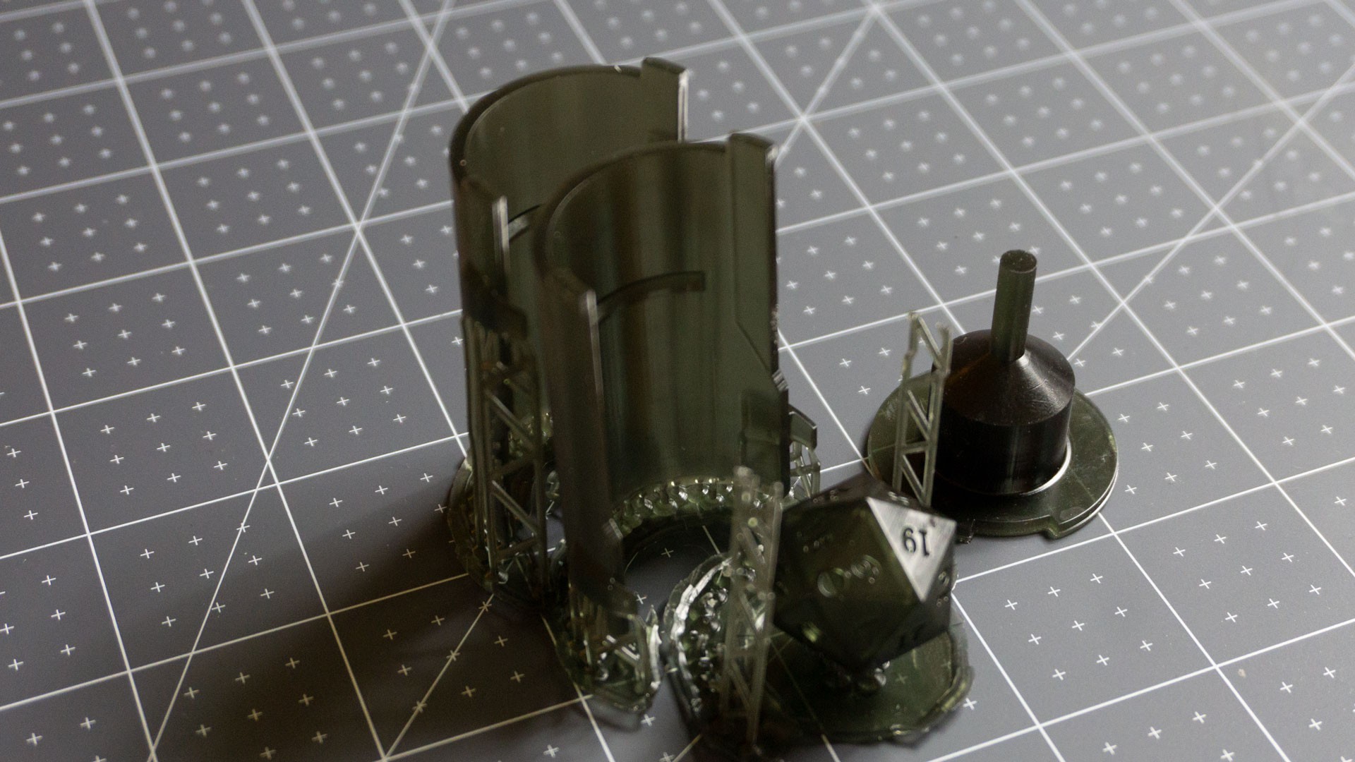
11/12. Demold and Clean up
The first demold and clean up doesn't need to be too precise, as I'll be casting the whole thing again. By the way, the reason I cast the dice in two steps is so that the electronics can be properly centered!
13. Place PCB in final mold
For this second casting, I did create registration pins, this really helps line things up quickly. Of course this is something I was able to do without modifying the PCBs, I just had to make new molds.
14. Pour / cure / demold redux
The second pour is pretty much the same as the first one, although in this case, we really want to leave the resin to cure under pressure for as long as possible, in order to get as good a surface finish as we can.
15. Clean up
You see me use an exacto blade to cut the sprue off here for a good reason. I want to make sure and create a proper tip where the prue was, rather than a very rounded corner. You may also notice that the mold cut lines are along the edges of the die, rather than in the middle of the faces. I'm hopeful that production versions of the molds will also be able to do this to reduce the amount of cleanup and sanding necessary.
16. Sand and Polish
This step can take a long time if the casting and initial molds weren't up to par. I also would like to investigate alternative ways to cut the sprue cleanly, leaving really sharp and smooth surfaces. I don't know if that will be possible, but if it was, then sanding wouldn't be needed at all.
17. Paint Numbers
The final step is, of course, to paint the numbers. I used a simple acrylic paint and, as you can see, just rubbed off the excess paint. I think professional dice manufacturers use a tumbling machine to both remove the excess paint and round off the edges. I tried using a small rock tumbling machine myself, but it didn't quite work. I'm sure I'll be able to sort it out with the factory once I get to that point.
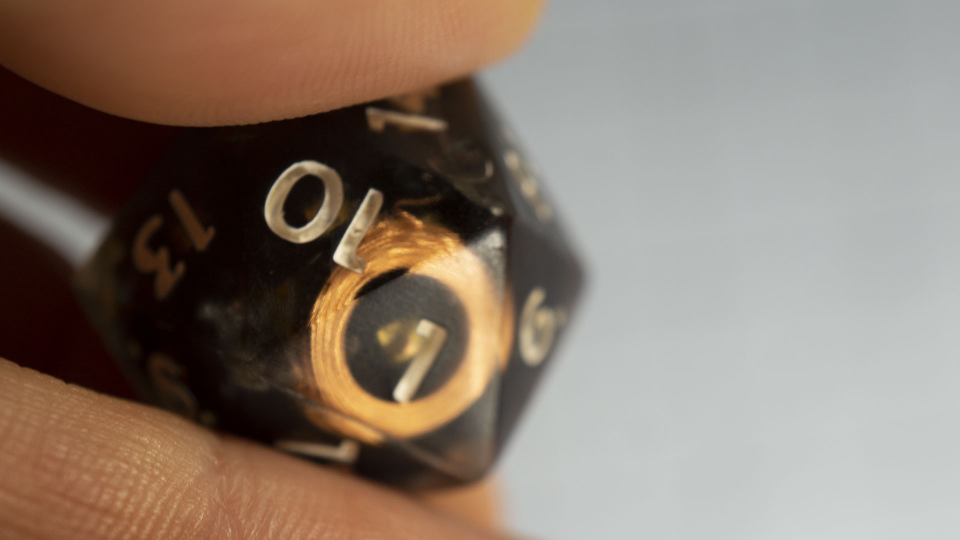
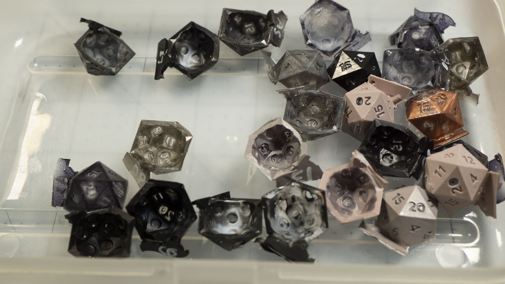
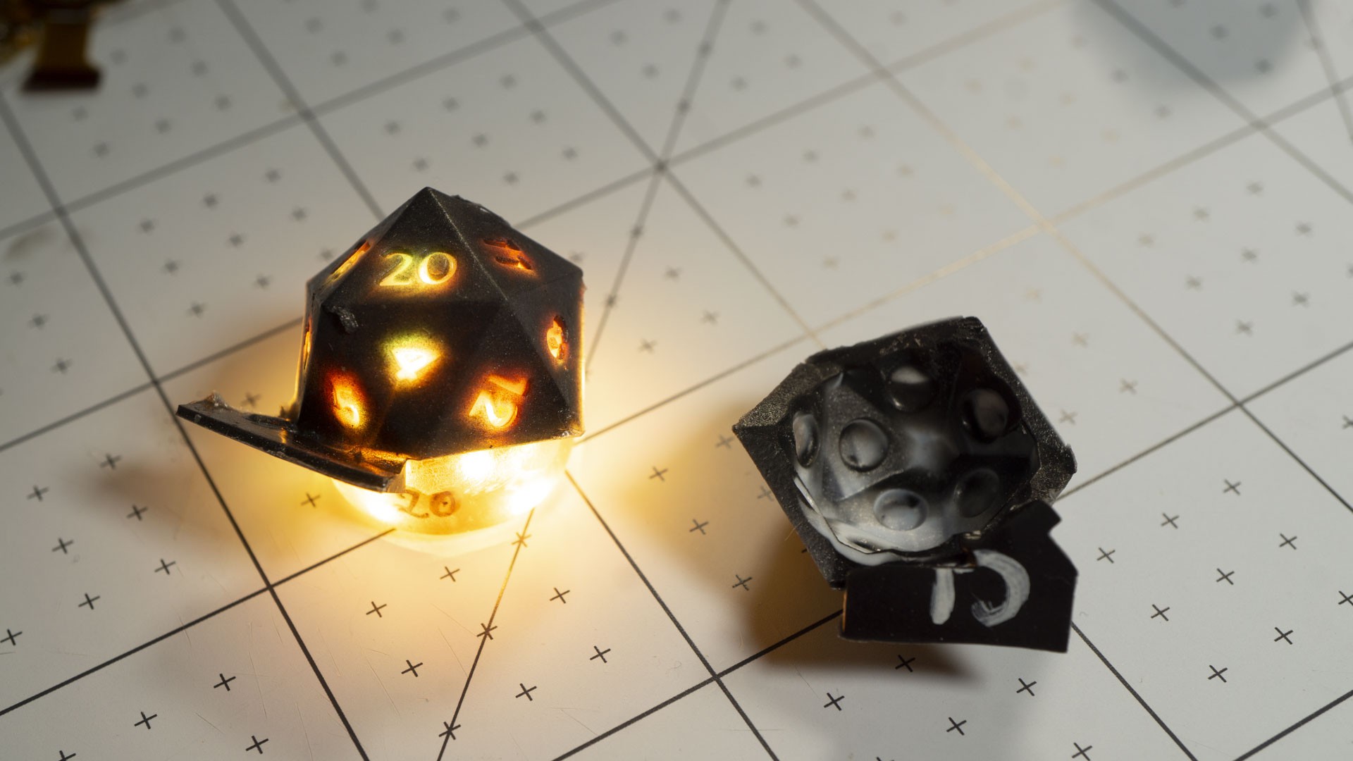
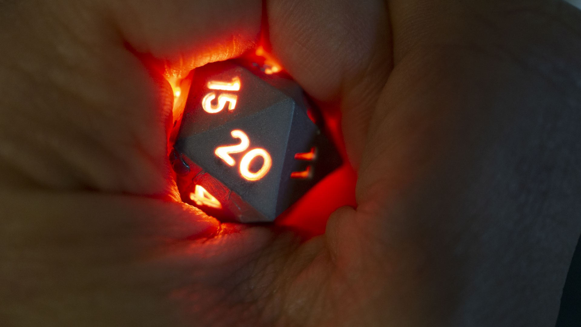
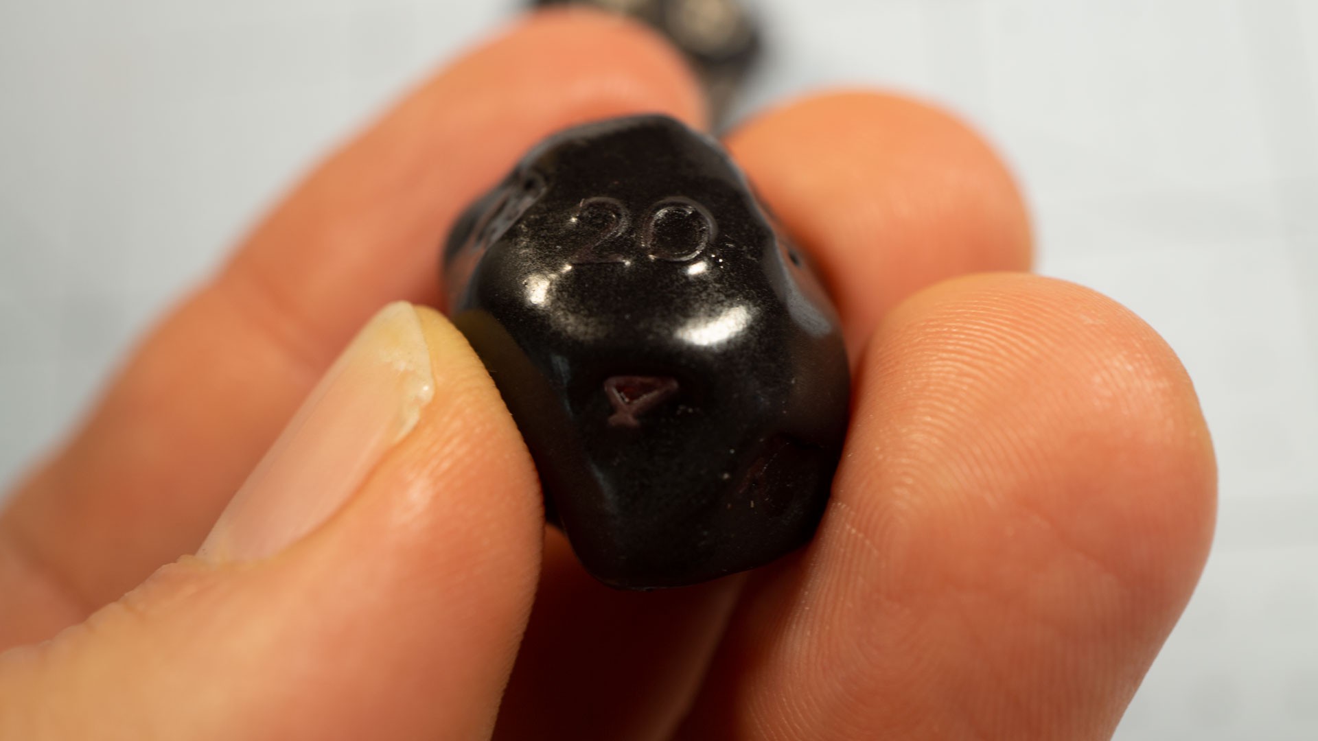
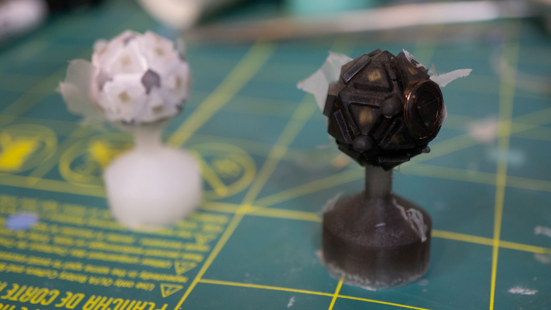
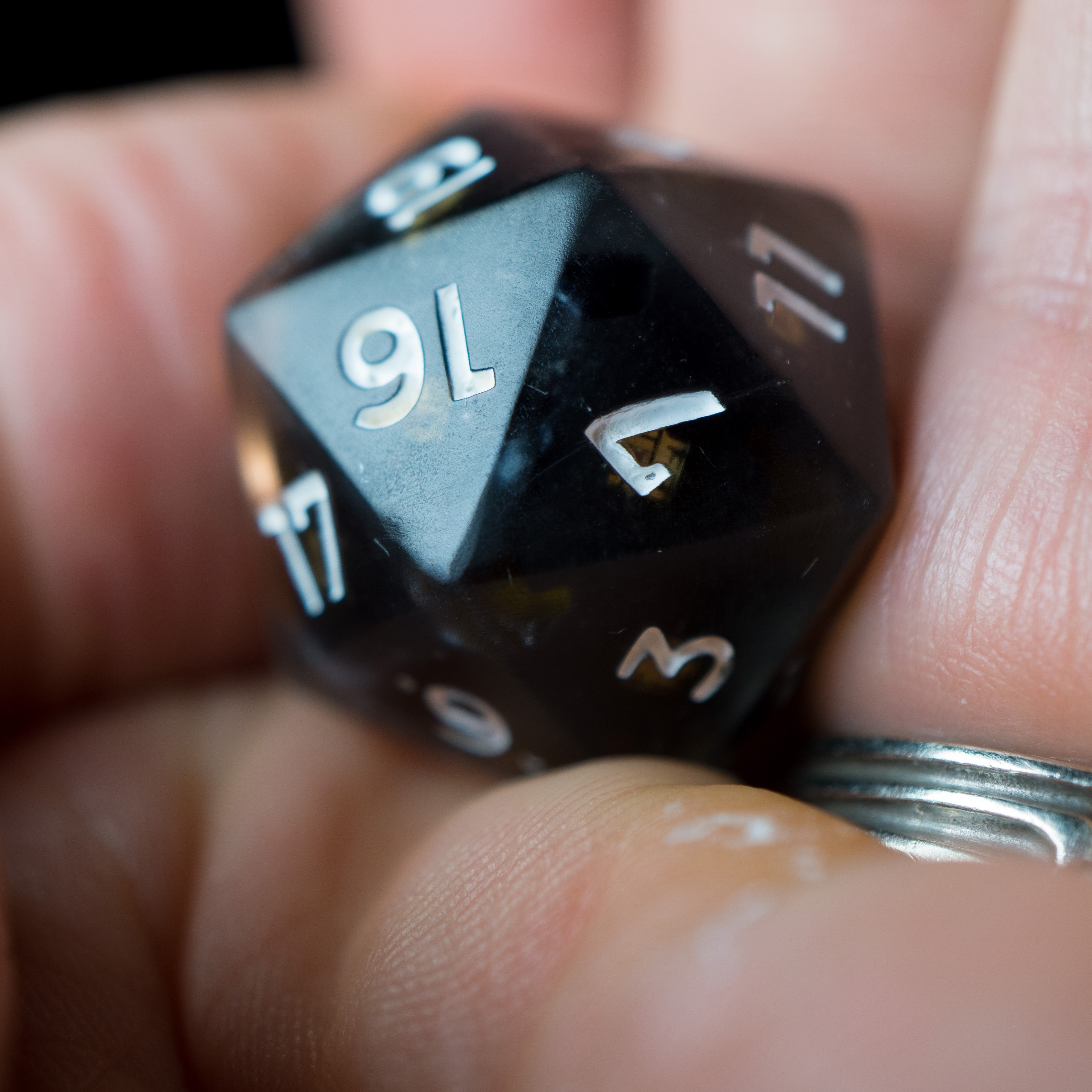
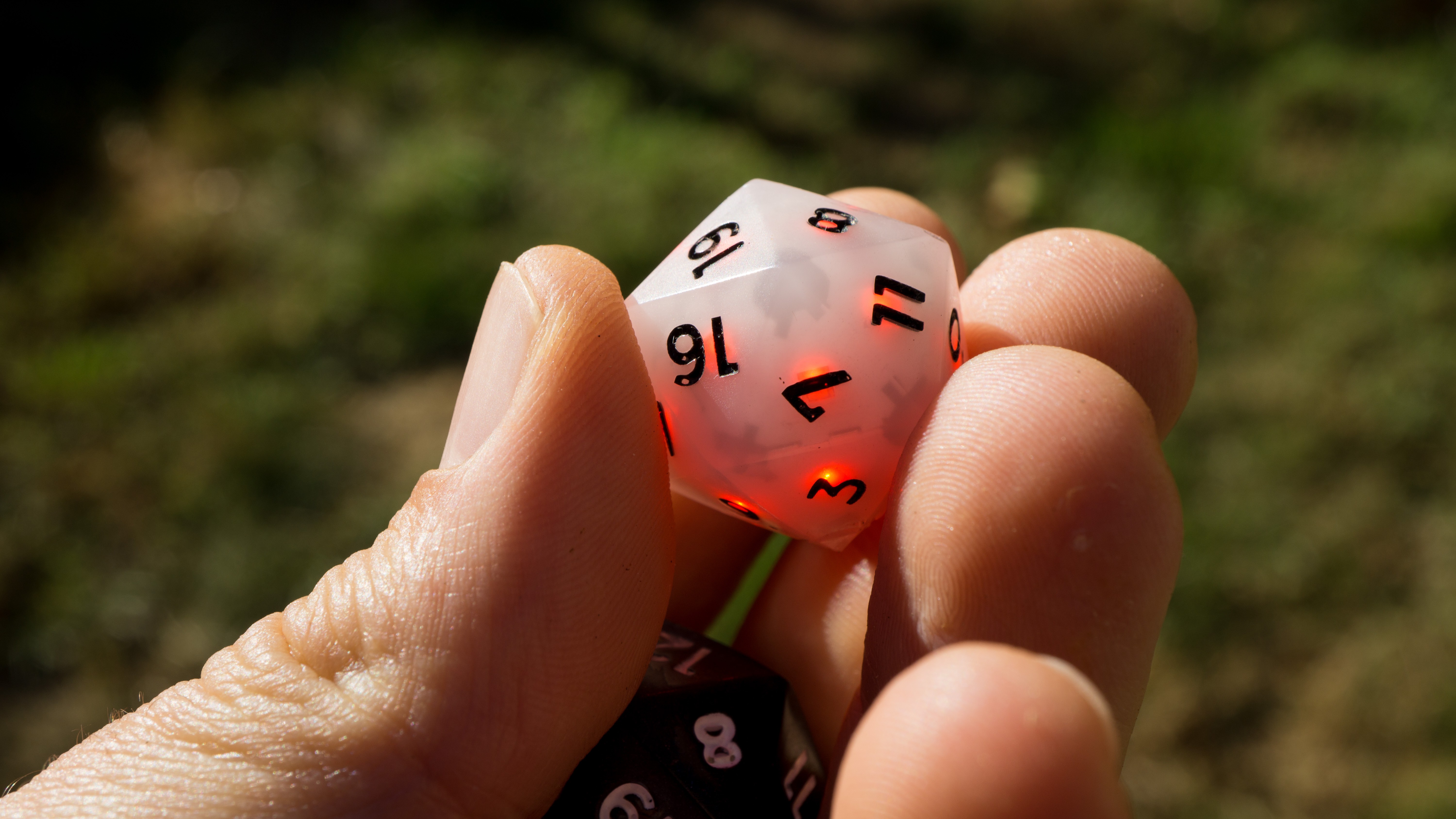
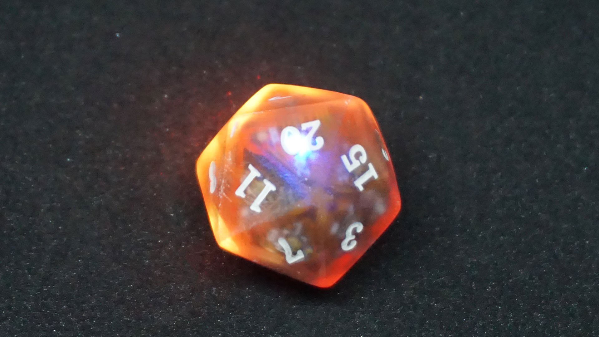
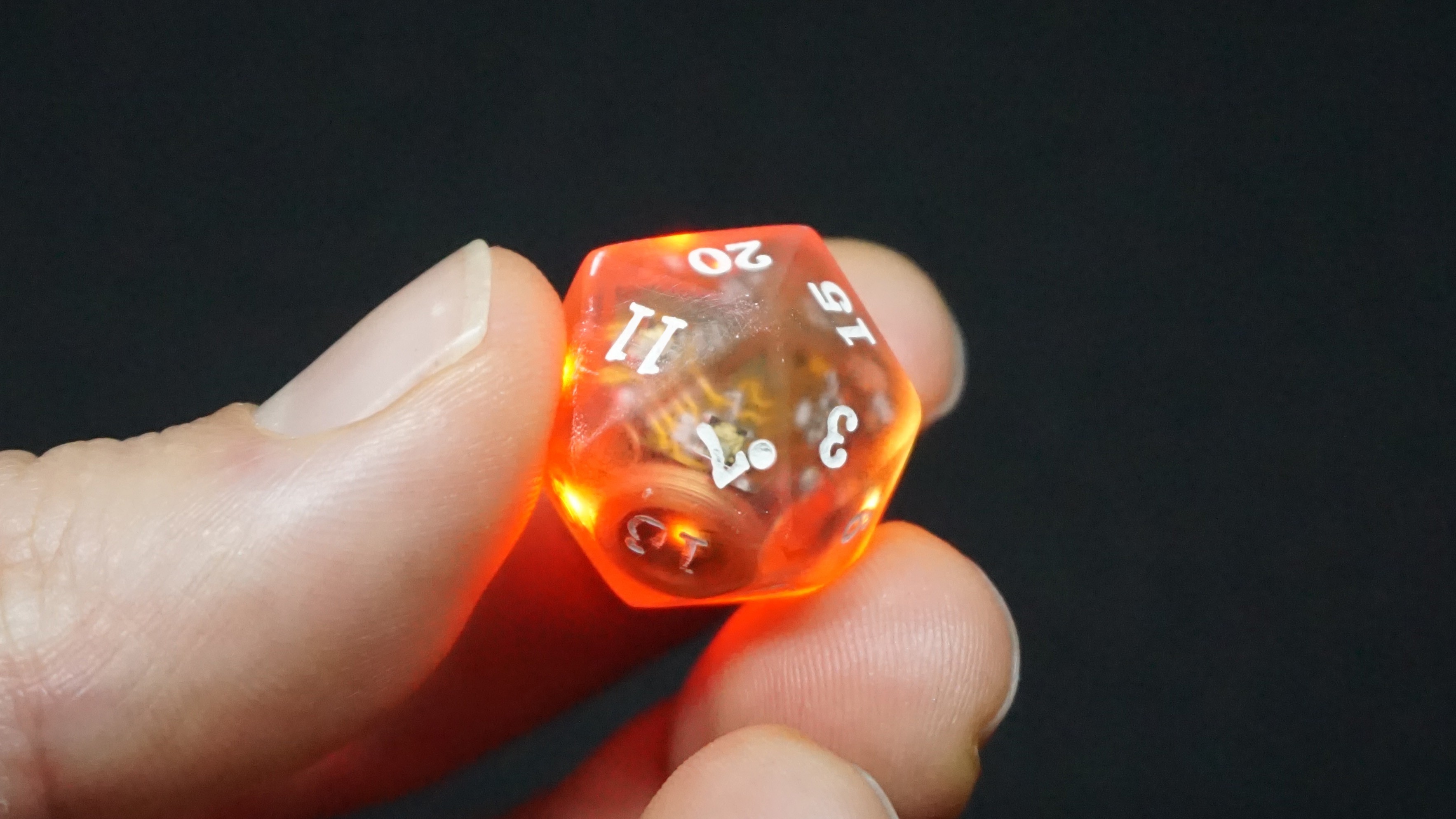
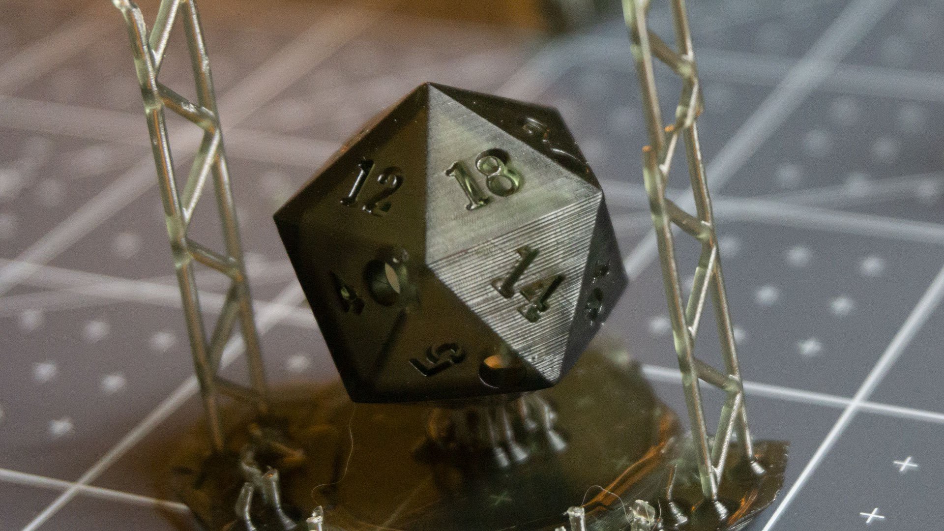
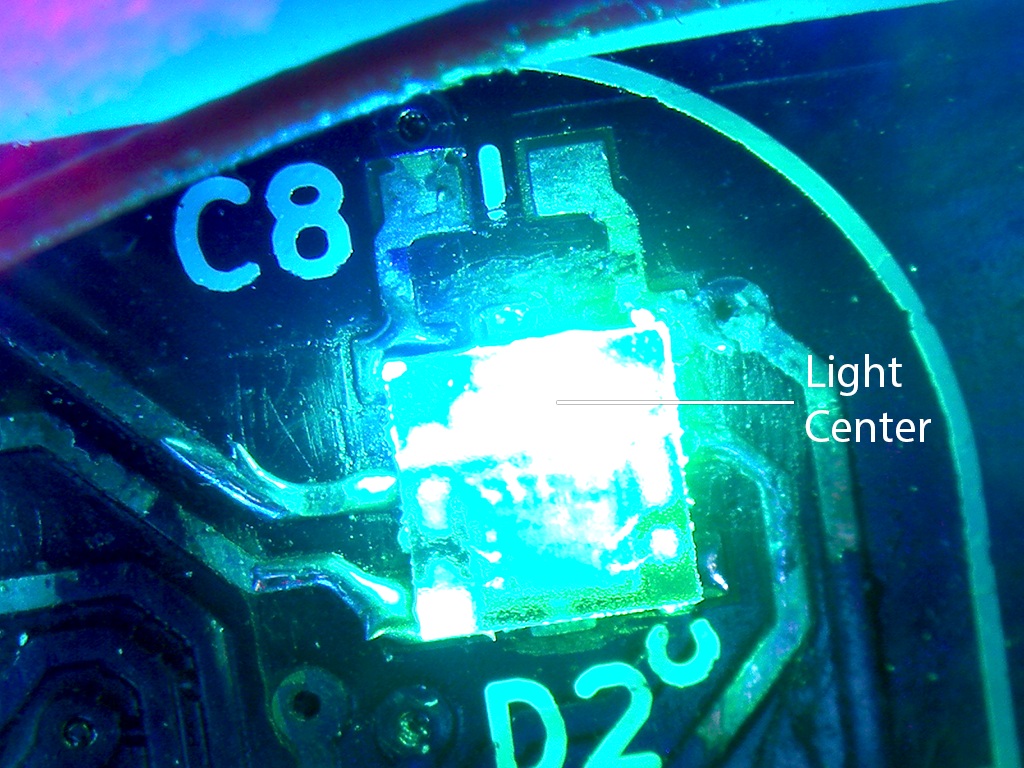
A quick update with pictures of the updated D20. I am testing different combinations of materials and silkscreen colors for the dice.
The challenge here is to find a combination that diffuses the light nicely, without blocking most of it out and still looking interesting when off.
---------- more ----------
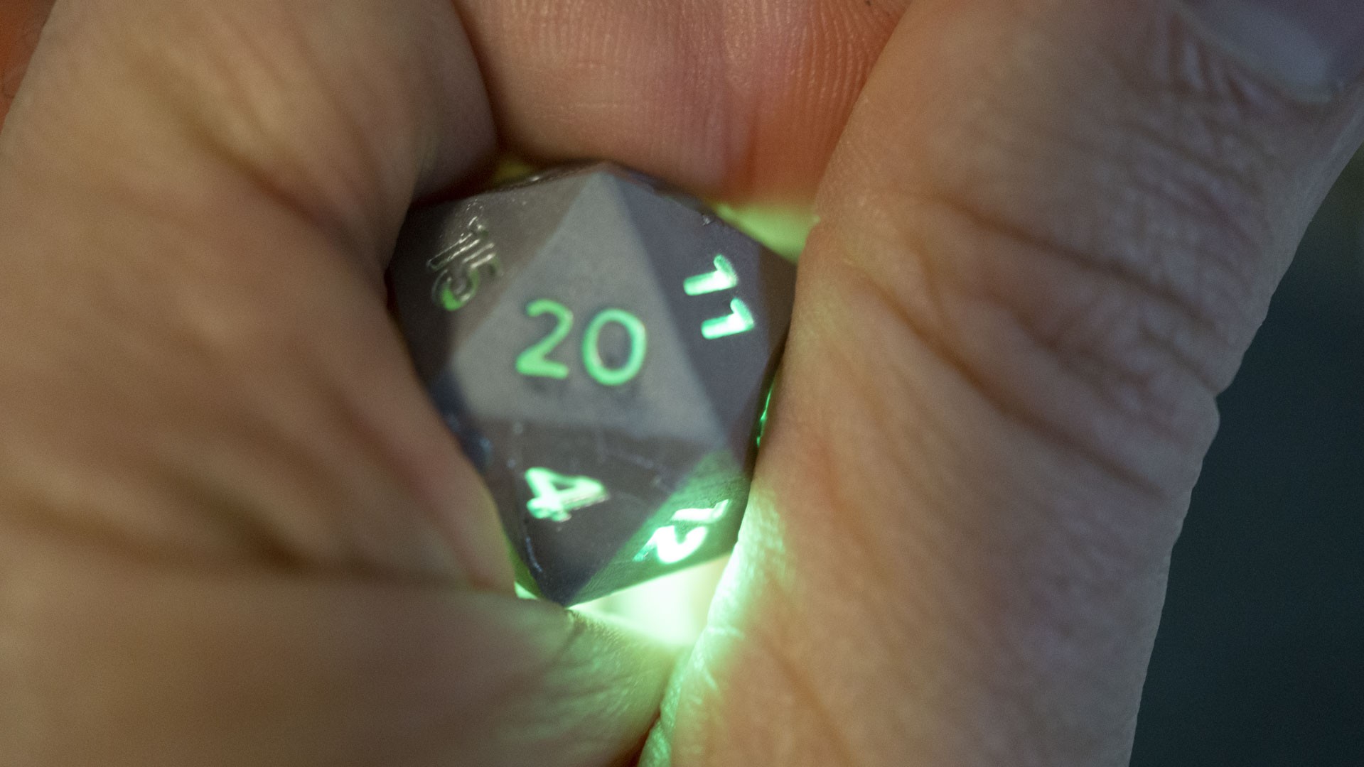
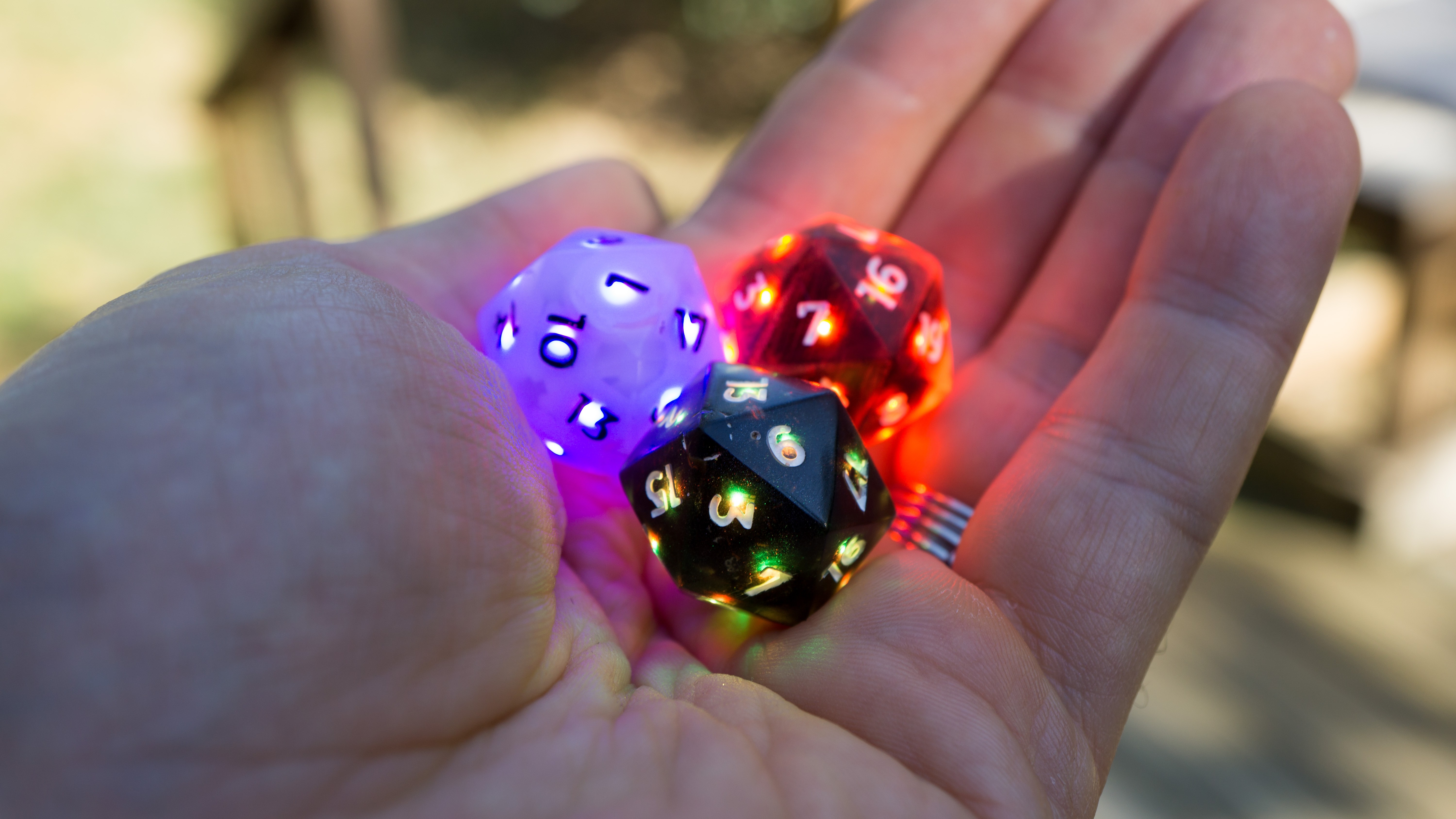
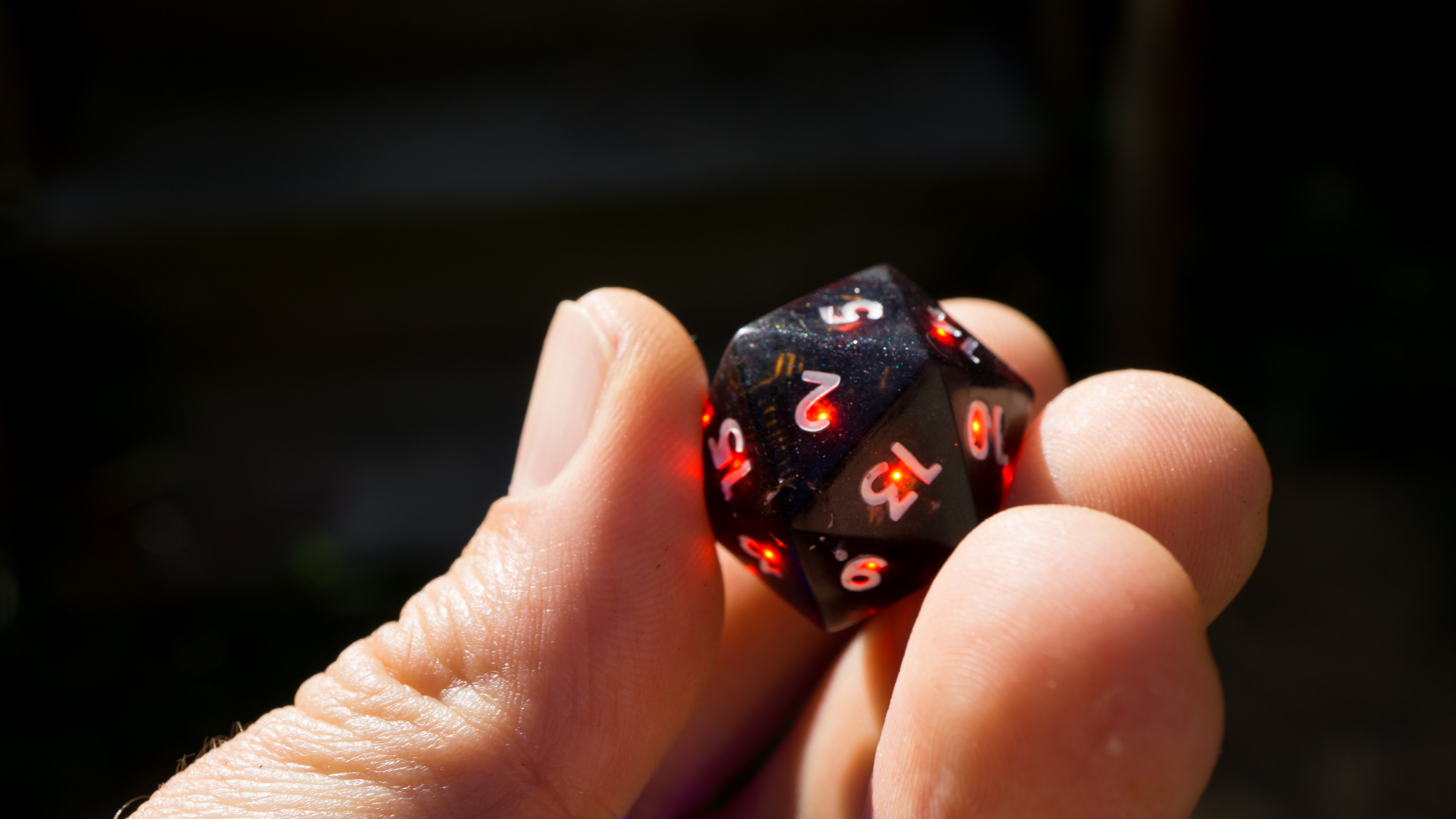
This is what the black and white die look like in bright sunlight. There is only so much the LEDs can do at this point, but, hey, that's why it's important for the dice to still be readable when off.
Hello again friends! It's finally time for an update on the Electronic dice. I just returned from showing the latest version at Gen Con, and it was fantastic! So, what's new?
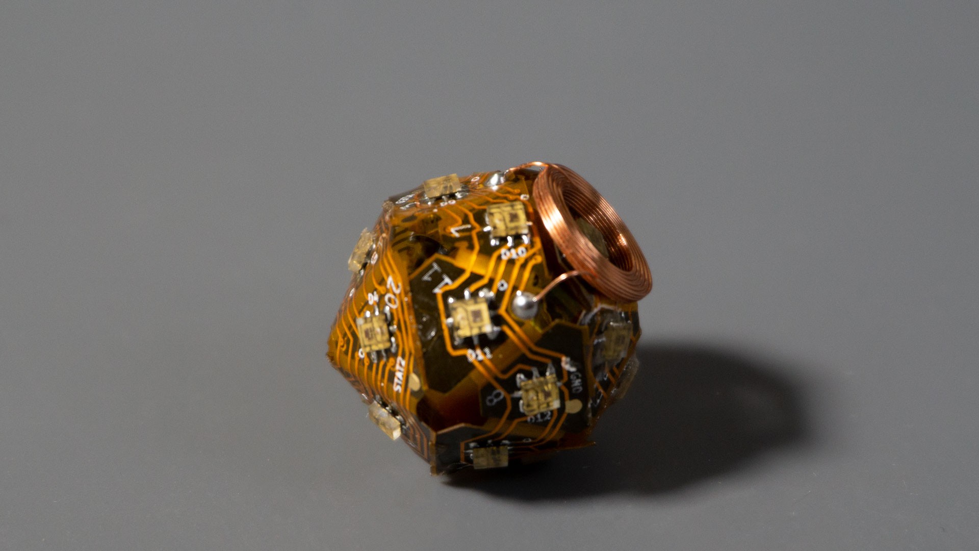
Well, first and foremost, the new prototype is of a D20! Still regular size, still full of LEDs, still inductively charged, and still awesome. In fact, I think the D20 is by far the most fun light up die. There are, however, several other differences with previous prototypes.
---------- more ----------
New board
Because this die is 20-sided, the pcb had to be different, and while the volume of a 20-sided die is greater than that of a 6-sided die, each individual face is smaller. That made designing the PCB quite a challenge. Who am I kidding, I loved it! Figuring out how to fit everything in was delightfully painful :)
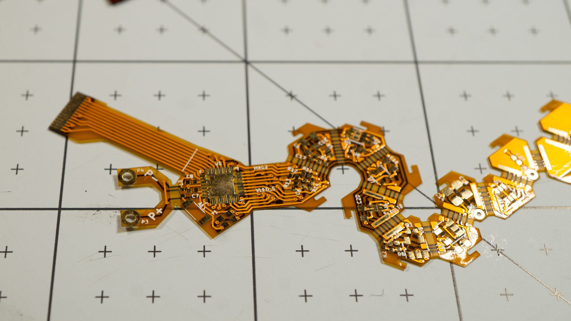
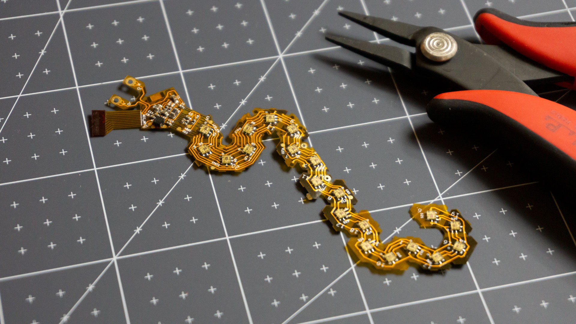
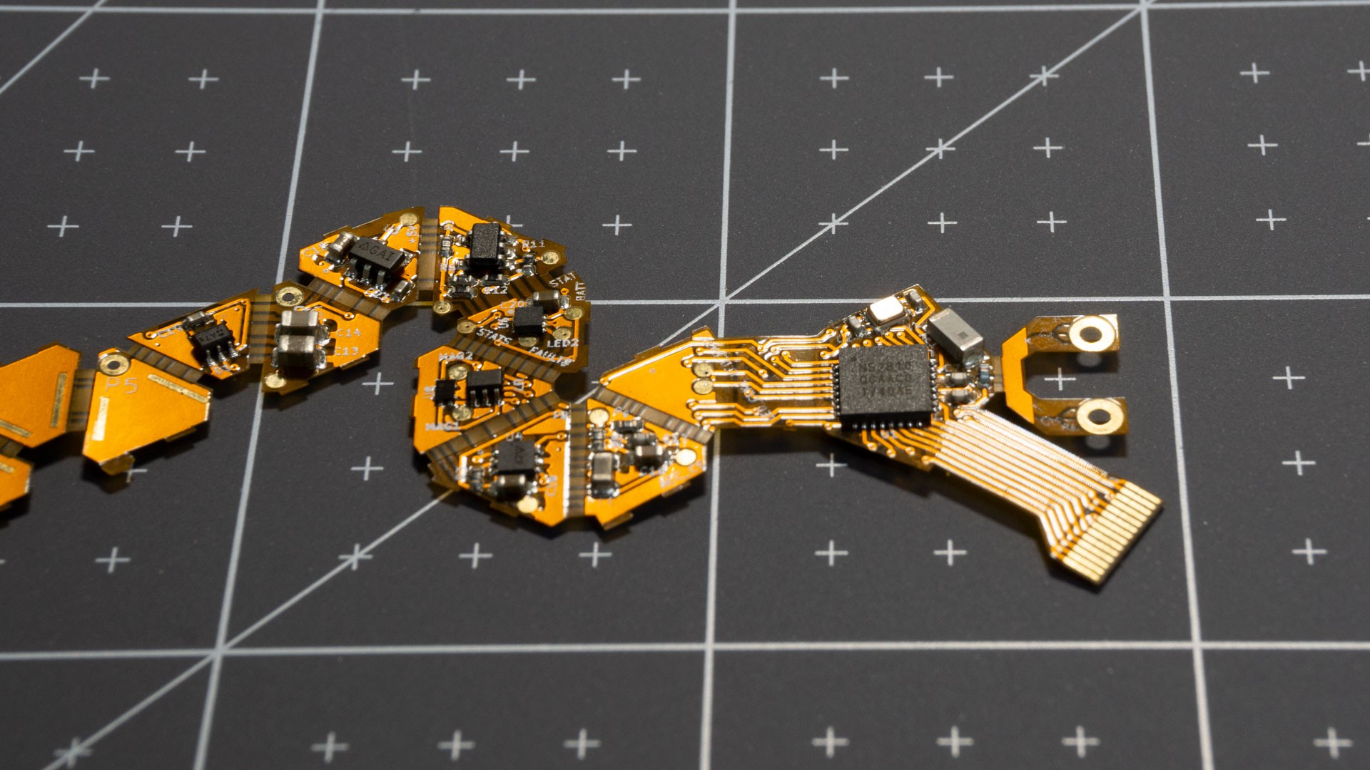
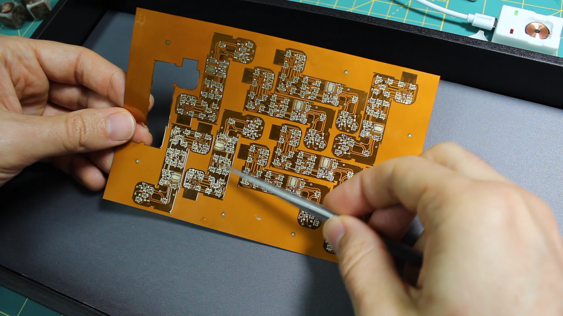
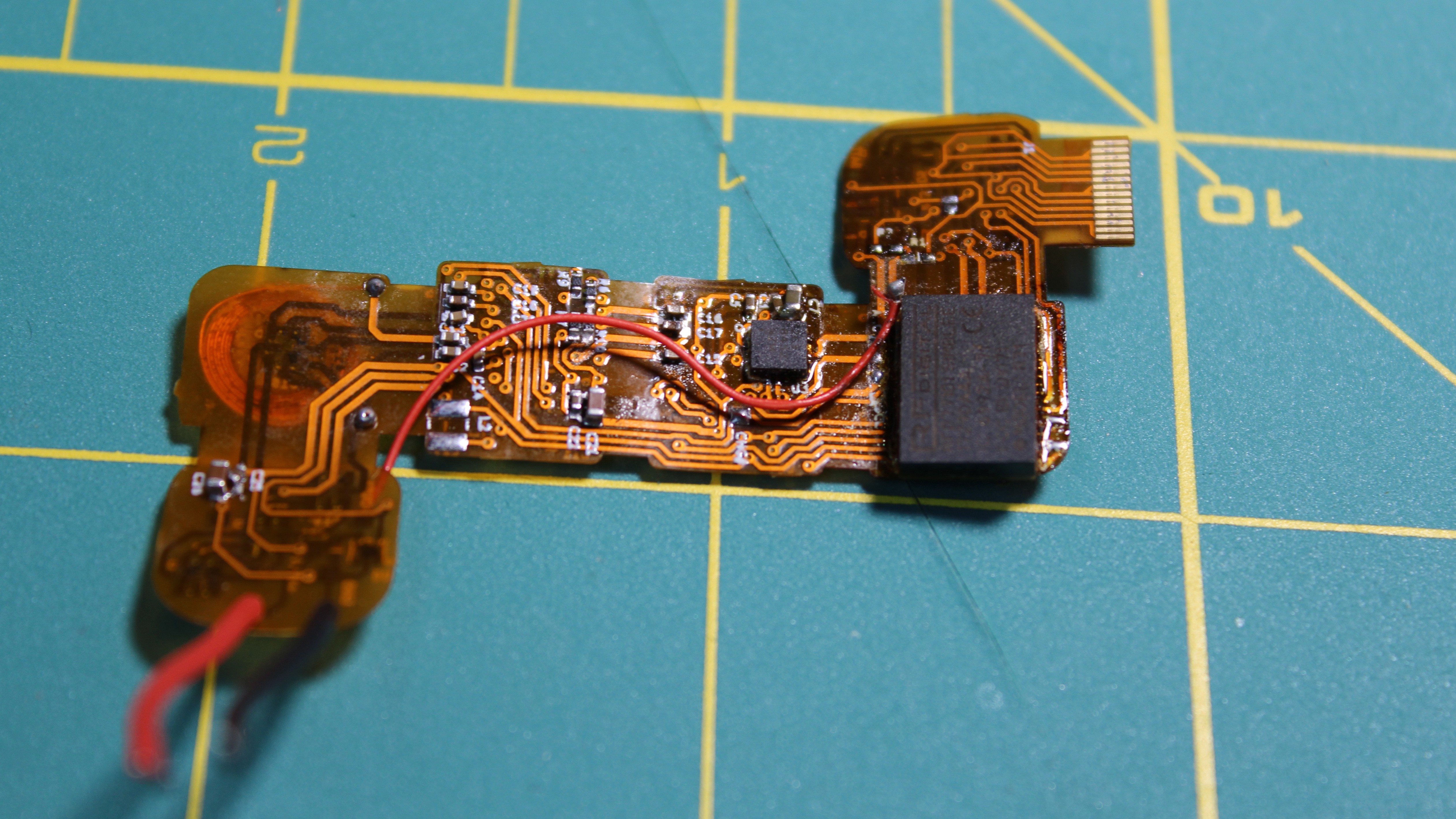
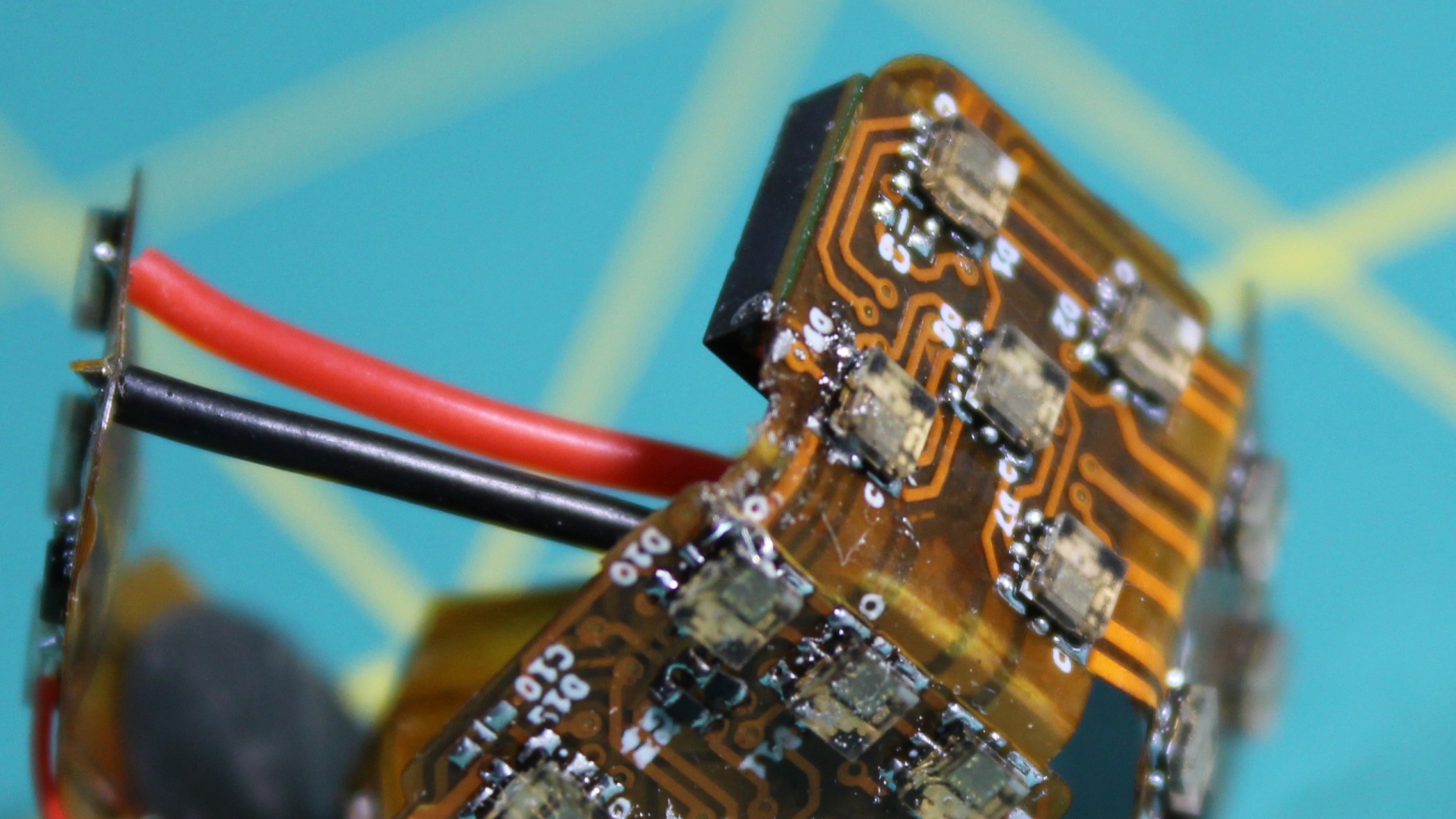
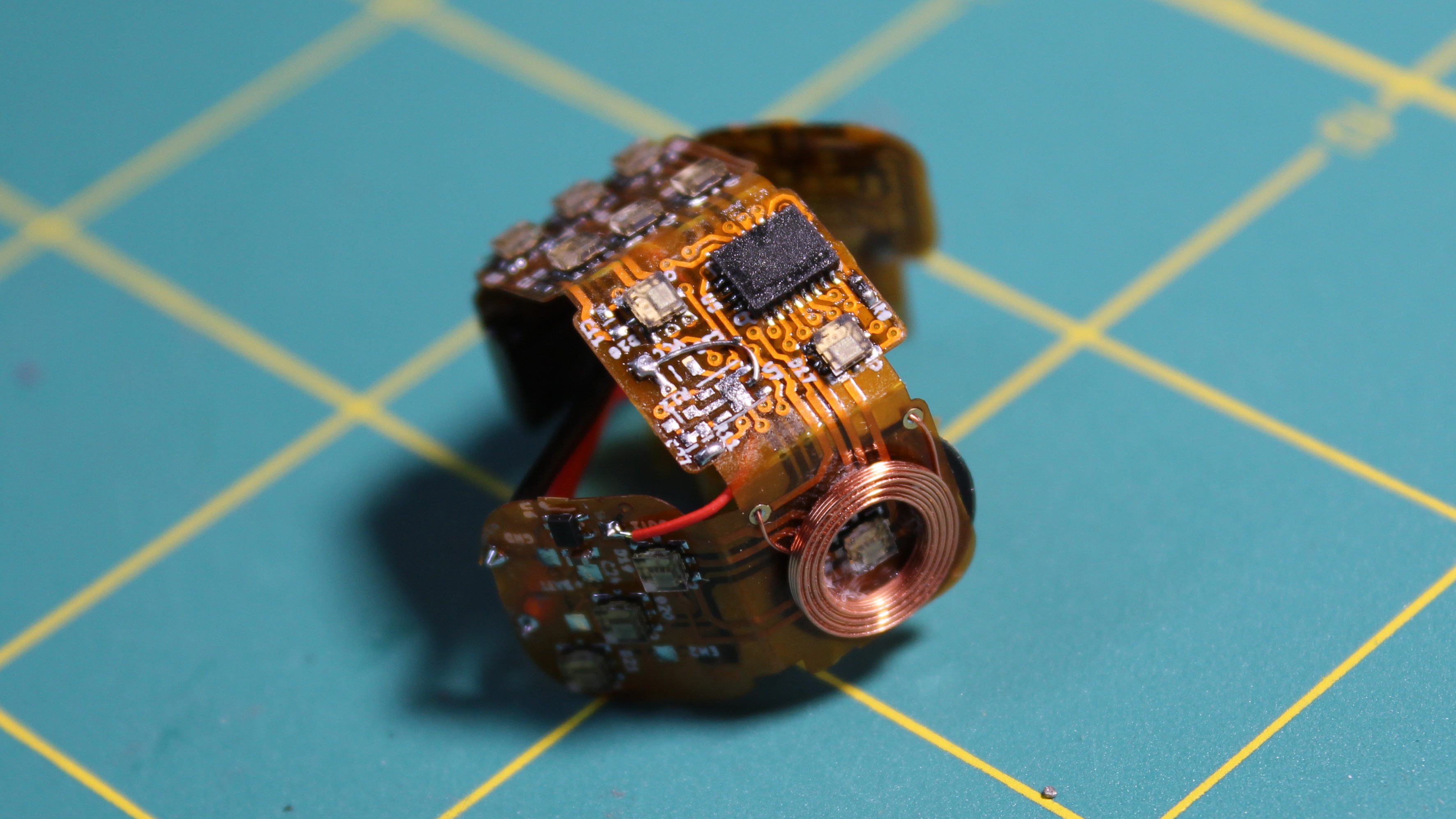
20-sided die PCB, I call it 'The Dragon'
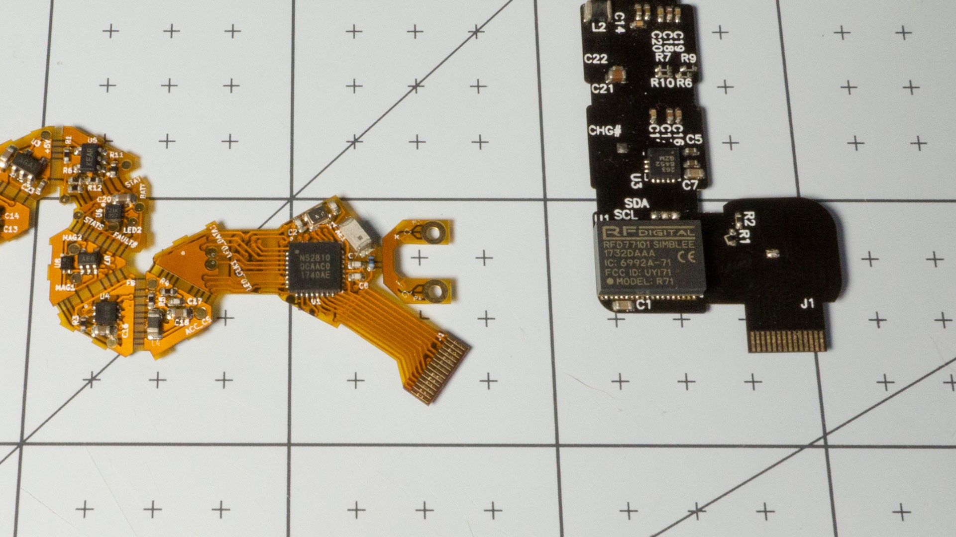
The PCB is an unfolded icosahedron with a couple extra bits. Each face has an LED on the side facing the outside, and possibly some components on the inside. This is still a 2-layer board.
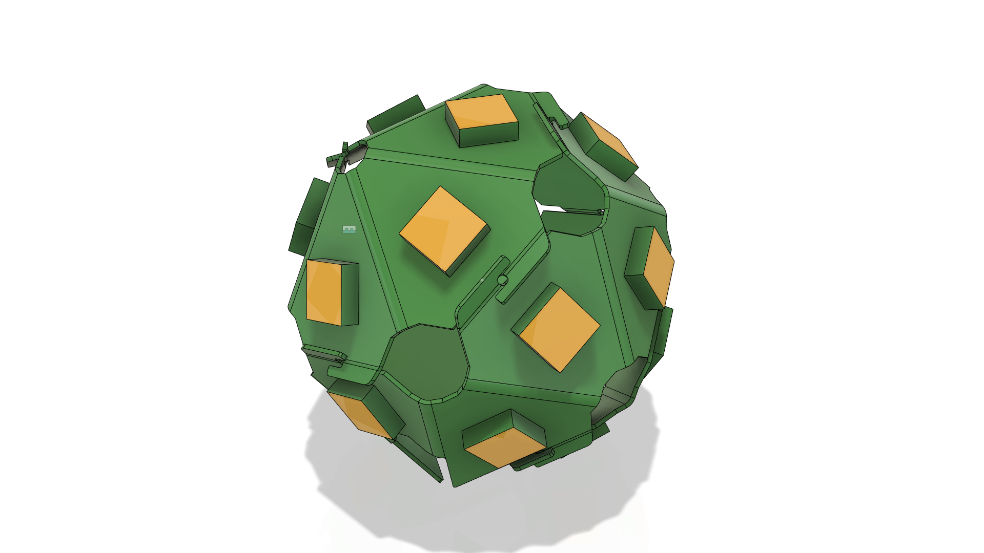
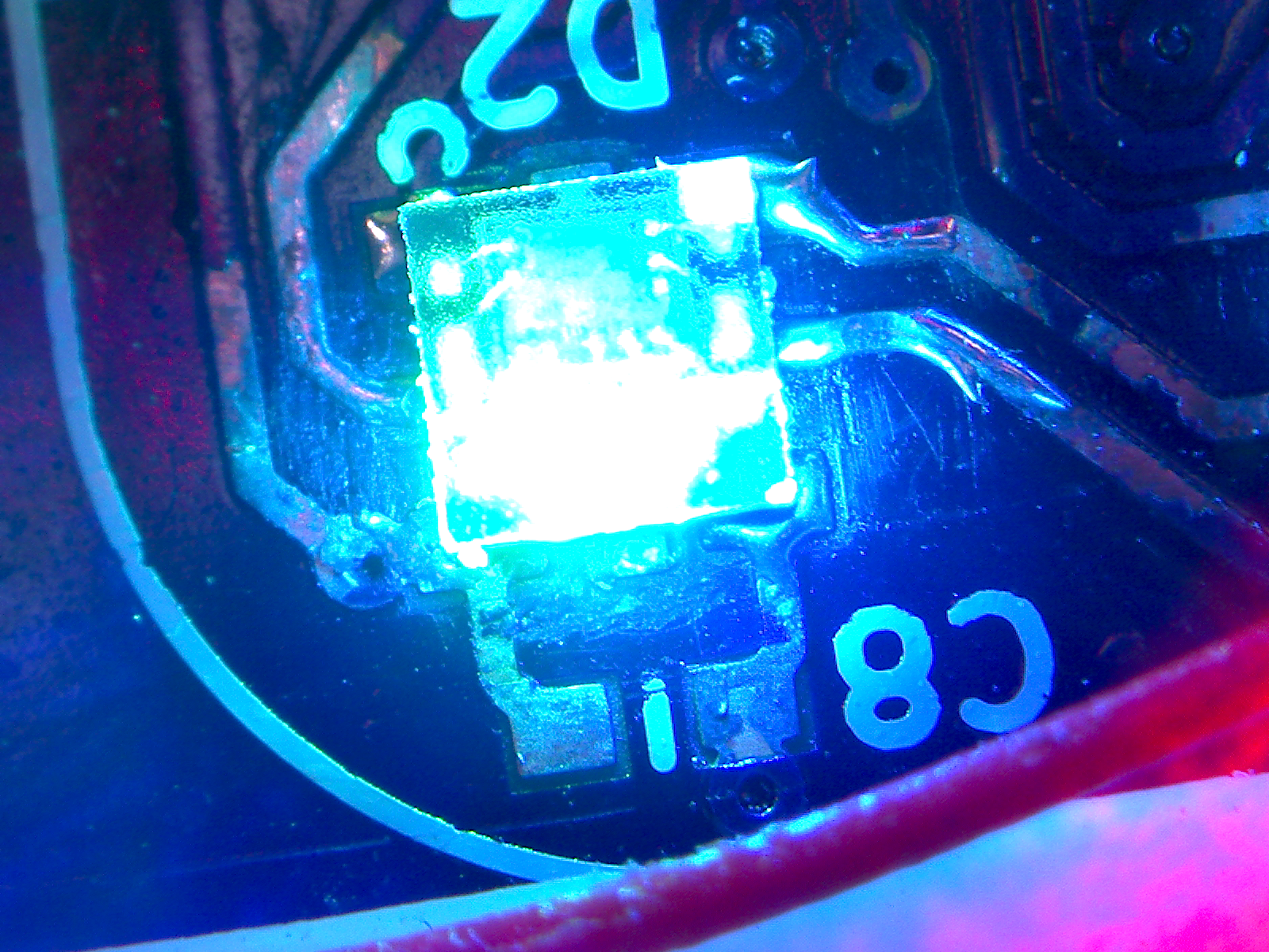
Close-up of the other side with most of the components.PCB folded up and ready to be put inside a die!
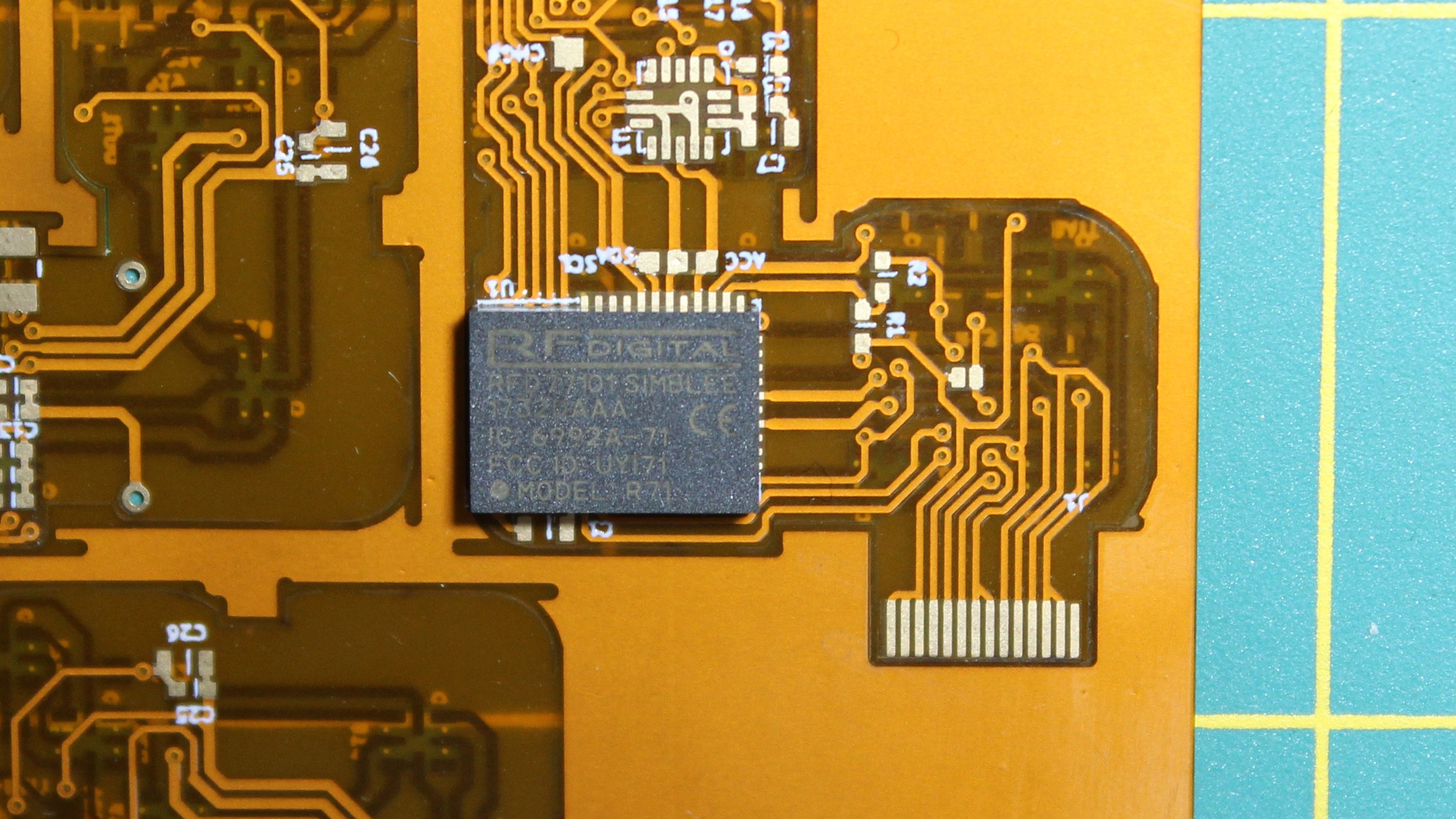
New Chipset
This version of the dice revolves around a nrf52810 from Nordic. The previous version centered around a Simblee module, and while that was incredibly useful to get things up and running (with its arduino-compatible toolchain), the module itself was way, way too expensive. The best deal I could get for small quantities was about $16. The economies of scale couldn't bring that down far enough to make the dice remotely affordable. The Nordic chip, on the other hand, only costs $2.50 in small quantities. Adding a crystal and chip antenna to actually compare apples to apples only brings that cost to roughly $3. That is an enormous difference.
Of course, changing the main microcontroller / toolchain / SDK means that most of the firmware code had to be rewritten, which was a bit of a pain. On the other hand, it also means that I now have control over things I couldn't before, such as the bootloader or even customize the bluetooth advertising packets.
Move over Simblee!
The Nordic SDK is full-featured and the developer community is very active, which means that getting answers to questions is a lot easier. RFDuino, on the other hand, has basically fallen off the face of the internet since they got acquired...
The new microcontroller is also faster than the Simblee module. Simblee internally used an nrf51, the previous generation compared to the nrf52. That is great because it means the firmware can do more work to properly identify dice roll state.
Along the same cost-reducing vein, the accelerometer is also cheaper (new part# VS old part#). It isn't quite as precise (10-bit vs 12-bit), but it is plenty good enough for this application.
New charging circuitry
Another big change to the design is the charging circuitry. With the previous iteration, I went with a standard Qi charger chipset. That turned out to be more trouble (and cost) than it was worth. The thing is, Qi chargers are really, really smart. The Qi receiver (inside the die) samples the current being received by the coil and sends that information over to the transmitter (inside the charger) through some clever load modulation. The charger then compares that value against the amount of power it is transmitting, and if the ratio (i.e. efficiency) falls under a certain value, stops the charge and tells the user that something is wrong. When you're trying to transmit several Watts of power at a time to fast charge your phone, this is a great feature, and prevents wasting energy. Unfortunately, because of the physical constraints of the dice design, my power transfer efficiency is pretty low. The coils are really small, and *relatively-speaking*, a lot further apart from each other than the coil in a phone charger is from the coil inside the phone. This caused me a lot of headache, when I didn't really care about wasting at most 100mW of power (for reference, the battery inside the die charges at between 20mA and 40mA).
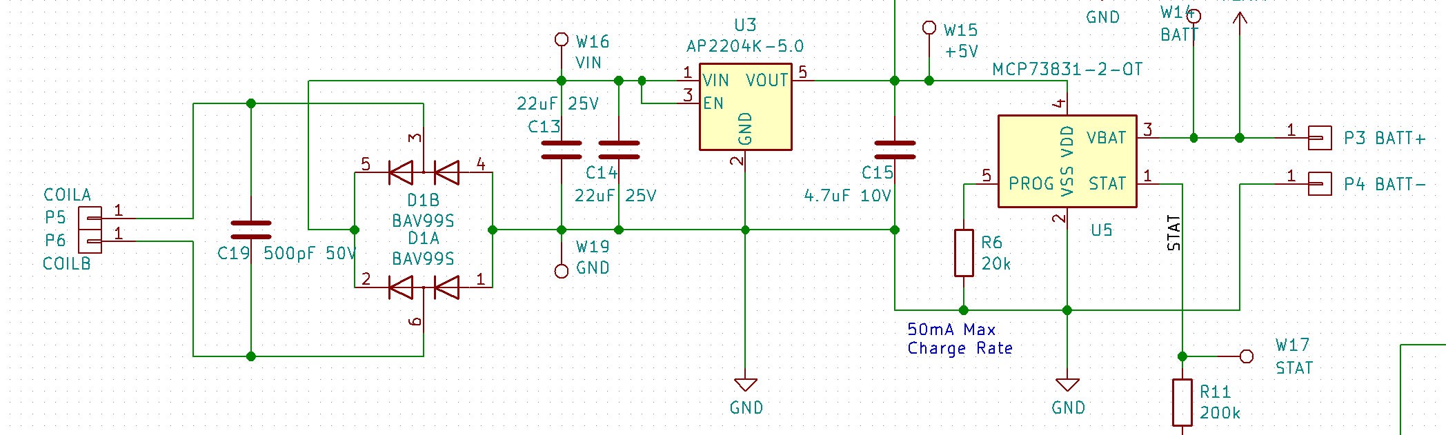
So instead of that, I went with a dumb charger set up. On the receiver side, I used a <clears throat> FULL BRIDGE RECTIFIER, a couple caps and a linear regulator to create a stable 5V supply from the coil input. Then I added a standard single-cell LiPo charger. I didn't even add any circuitry to decouple the logic supply from the charger's output as the load bias is pretty negligible as long as LEDs aren't lighting up! :)
This, of course, also had the side effect of reducing the cost quite a bit. Roughly speaking, the rectifier + LDO + LiPo charger combo came in at $0.15 + $0.10 + $0.50 = $0.75 compared to $3.00 for the Qi receiver/charger chip (BQ51050B).
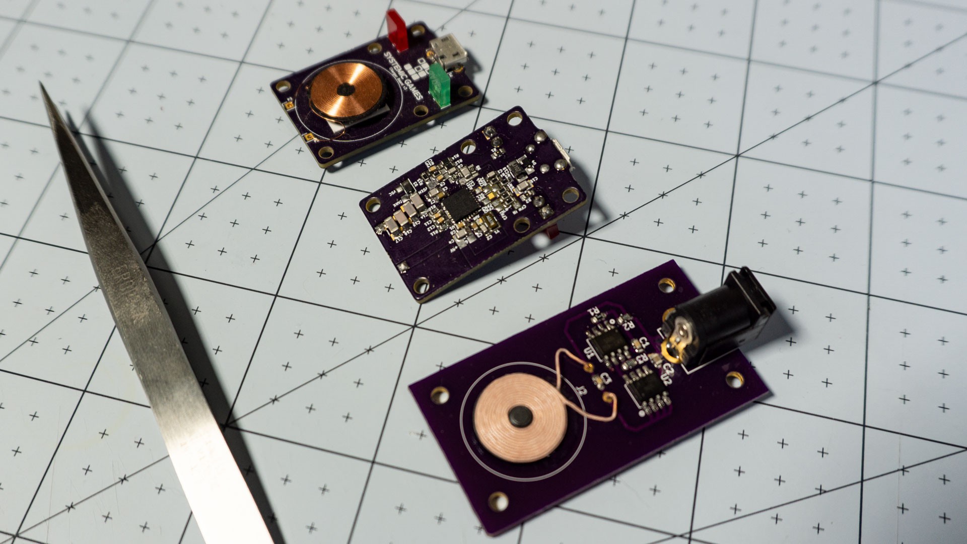
And that's not even the full story. The Bill of Materials for a Qi charger is quite large, in fact, the cheapest single-chip Qi transmitter (NXQ1TXH5) is another $3.00 or so. Compare that to the alternative, some cheap wireless charger chips off Alibaba (XKT-335 and XKT-412) for $0.15 a piece and you can imagine the overall savings. And since it seems likely that - on average - I'll need to provide a charger for each die, it's kind of like adding the cost to the die directly.
Previous Qi charger (top/middle) versus the new dumb charger (bottom)
So obviously the lesson here is that being really smart isn't always a good thing. ;)
Excluding the LEDs, the parts come out to about $5.50 per die (for a D20, it's about $7.50) if I were to make 1000 dice. Of course that doesn't include any of the assembly / manufacturing costs, which is why I've been telling everyone that my target price will be between $25 and $30 per die.
Resin Casting
It's really strange how sometimes you get so accustomed to something that you simply forget that things can be different. I think this is something most of us know, have seen or have been told about before, but it is really something you don't fully appreciate until it has happened to you! Sorry, I know this sounds very philosophical, but in this case I'm thinking specifically about an assumption I've made about the dice from very early on. That assumption was that the way to create the dice was to put the electronics inside a plastic shell in the shape of a die. In fact, the first design I uploaded on Hackaday.io featured a removable lid, so that you could replace the battery. Along the way, I figured out how to fit a rechargeable battery instead, and even an inductive charging coil. I was super happy with that upgrade, because it meant that I could try to pot the entire insides of the dice shell, battery, electronics and all, in resin, and make the dice that much more solid (and great feeling).
But it took me MONTHS to realize that I didn't need the shell at all anymore. I had been agonizing over how to design those such that they could be injection molded (and dealing with the draft angles, overhangs, etc...), and didn't even think for the longest time that, well, I don't need a shell at all! I could simply place the folded-up electronics inside a dice mold, and cast the whole thing just the way you would a regular resin die. It's one of those things that really make you go "Doh!!!".
So, yeah, the dice are now directly cast in resin. This, of course, brought a few issues of its own, but overall it was a massive simplification to the assembly process.
The first difficulty was simply me learning the ins and outs of mold making and resin casting. In the end, my process went like this: - 3D-print positives - Cast Silicone molds from positives - Cast resin dice from Silicone molds
If you're interested in more details, there are tons of resources on Youtube. I followed all of them, got a vacuum chamber (for the Silicone) and a pressure pot (for the resin) and things mostly came out good.
I did have one thing that really tripped me up, which was mold release: make sure you use the correct mold release!
There are two kinds: Silicone-based sprays and Oil-based sprays. Do NOT use Silicone-based sprays when you are creating the molds (Step 2 above). Otherwise what will happen is that the silicone in the spray will flow into all the micro features of your positive (and if that positive was 3D-printed it will have lots of them) and then proceed to cure along with the silicone that you're using to create the mold. The end result is the complete opposite of what you expected in the first place: you won't be able to remove the mold from your positive...
For the resin casting, you can use either sprays, or none really...
Anyway, casting the dice ended up needing to be a two-step process. The reason for that was to make sure the electronics and battery would stay in the middle of the die, and not float up, sink down or drift. The idea is that the first casting can register with the circuit board / LEDs, yet have portions that stick out and can themselves register with the second mold (i.e. final die shape). In other words, I start by making a solid 'puck' out of the electronics, and then fit that puck inside the final mold.
This process worked well enough to create a few dice for me to show off, but it isn't great yet. Even though the puck kept everything centered nicely, it could still be placed inside the final mold incorrectly, causing some misalignment between the LEDs and the faces. I am investigating a different registration method that does require a bit of sanding afterwards, but that sanding is already necessary cut cut off the sprues left over from the casting process.
The jury is still out on how this process will affect manufacturing costs. Injection molding plastic shells is really cheap, cheaper than resin casting, but with the previous design I would still have needed someone to fill the shells with resin and then fit the top cover. All that while making sure there were no air bubbles - a difficult task. Here I need someone to do two resin castings / cleanup per die. It seems like more work, but it's fairly commonly done already. Obviously I need to get some quotes.
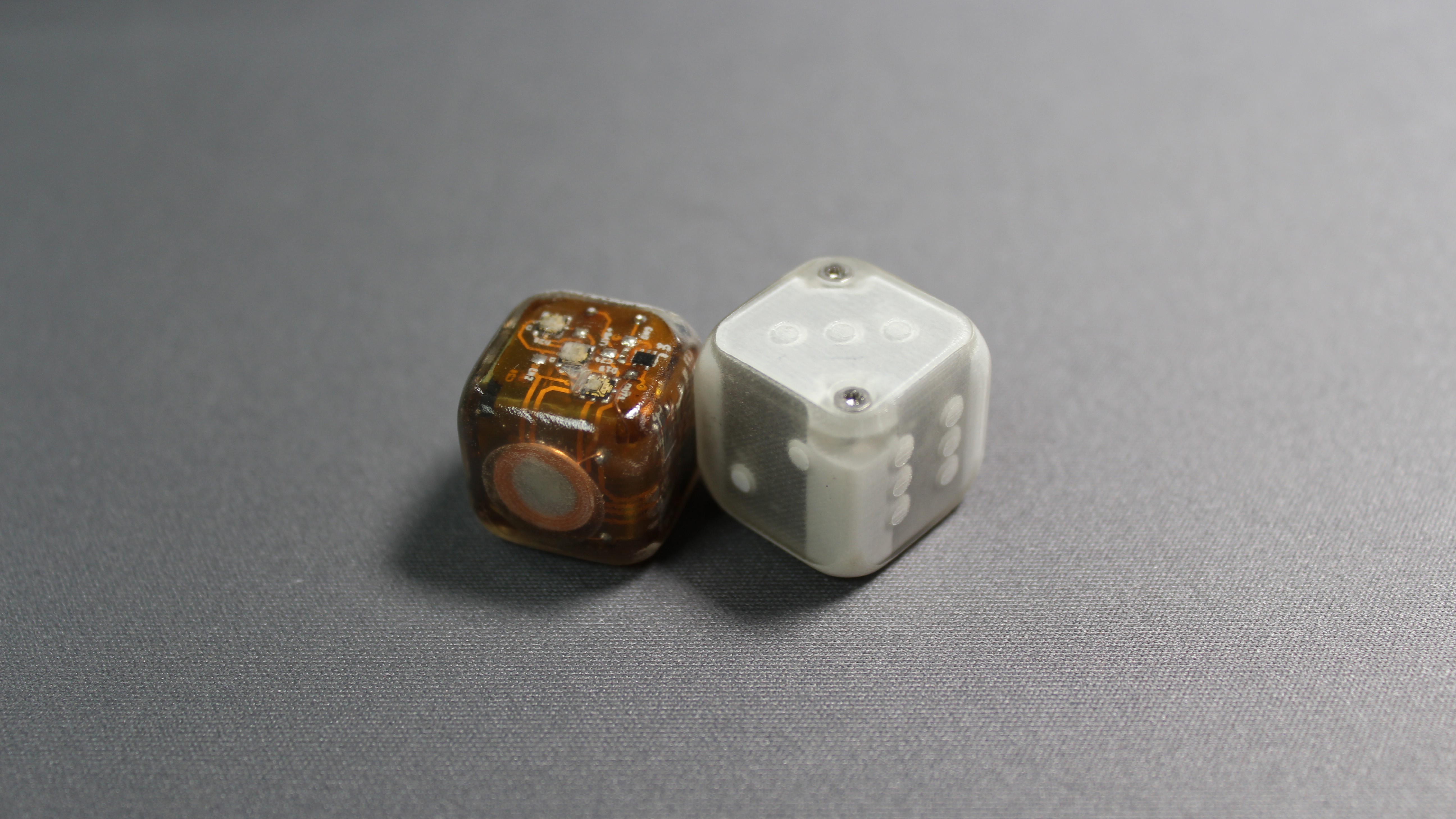
This is the next revision of the Electronic Dice. I've spent a lot of time putting it together, and it is really coming along!
Looks pretty nice, doesn't it?
So first things first, this version is exactly 16mm, the same size as a regular dice. And as you can see here next to the previous prototype, it is also more rounded. It's amazing how much difference 1mm can make, both in how the dice feels in your hand, and how much harder it is to put together!
---------- more ----------
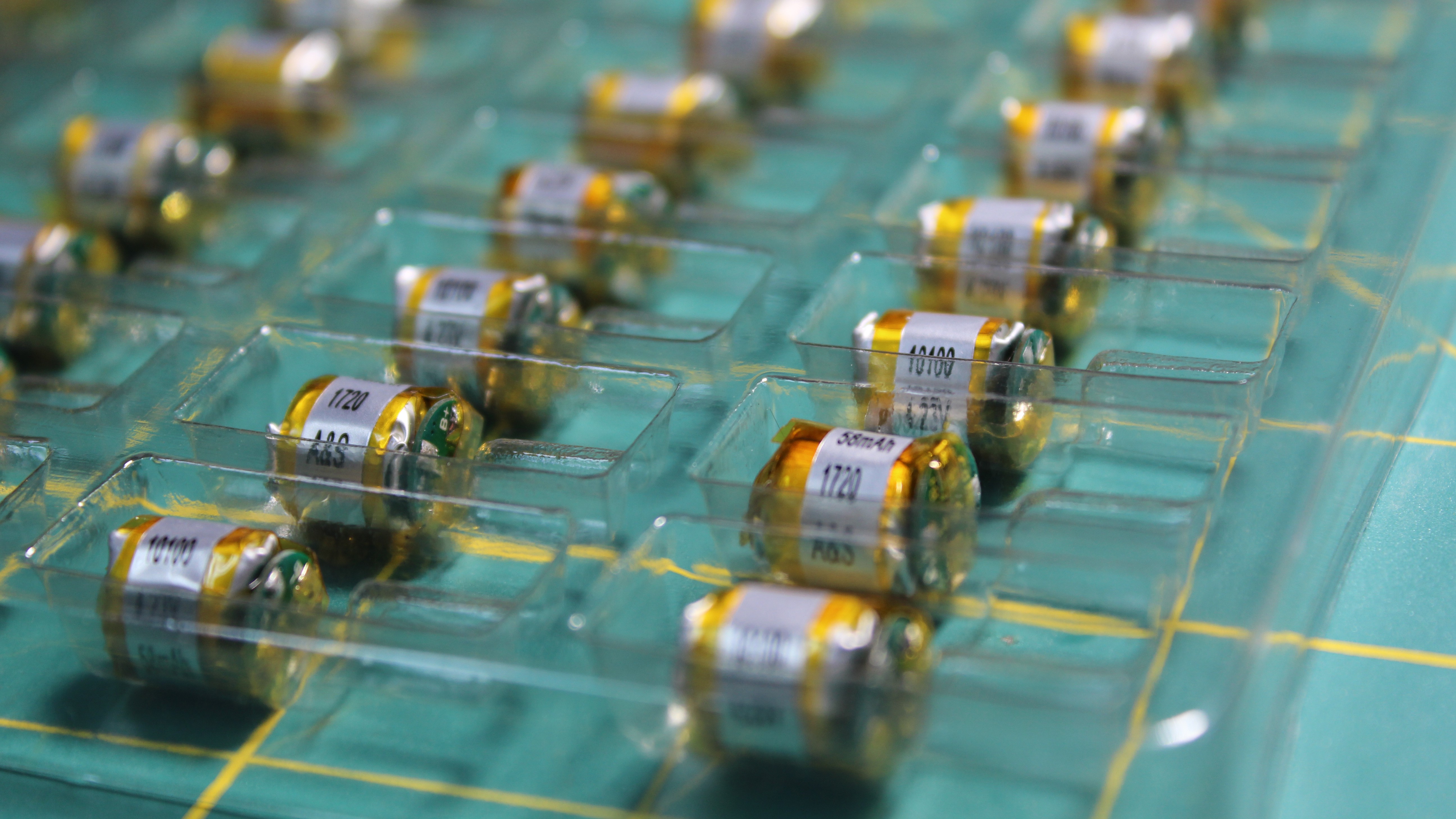
Of course, the other thing you might notice, is that this version doesn't have screws, or a removable lid in fact. Actually, this is a great example why sharing your work matters. In the last video, I specifically mentioned how I wasn't able to find a rechargeable battery small enough to fit in the case, and therefore why I had to design the dice with a removable lid.
Well, somebody mentioned searching for Bluetooth headset batteries, and sure enough, as soon as I started plugging in the right keywords, I was able to find small lipos on Alibaba.
These things are nice, they can supply enough current to light all the leds at once, although, obviously, that would drain the battery really fast! Of course, having a rechargeable battery isn't much use if you can't actually recharge it, and this is how I got to research inductive charging. This was a completely foreign area for me, and in fact it turned out to be pretty complicated. Not being all that comfortable with analog circuitry and magnetics, I looked for two things: a wireless coil that could fit inside the case, and whether there were integrated chips that would take care of the transmitter/receiver pair.
Well it turns out, Qi charging is pretty popular these days, and so there are several integrated chips that will take care of everything for you. I even found a Texas Instrument chip that would rectify the inductive current AND charge a lithium-ion battery, and all in a tiny package too, the bq51050.
The coil was also not too hard to find, a quick search on Digikey turned up several candidates.
After that, it was ‘mostly’ a matter of following the application notes on the datasheet, using the formulas they provided to compute the values of certain key components and giving it a try. I was hopeful that a standard Qi charger would just work with the dice, but unfortunately it didn’t.
It turns out that the two coils involved in the transfer have to be pretty well matched in order for the magnetic flux to induce enough current on the receiving end. So if my receiving coil was going to be a lot smaller than normal, then my transmitter coil needed to as well.
The other thing I found out, was that when you scale down the coil geometry, you need to scale down all of it, including the distance between the coils. It’s obvious in hindsight, but it took me a while to realize that. And so, while with standard Qi chargers you the coils can be 3mm appart, with a 10mm coil, they needed to be less than 1mm apart to be able to transfer enough power.
This posed several problems with the design which I’ll get into in a bit. First let’s finish the tour.
Flex PCBs
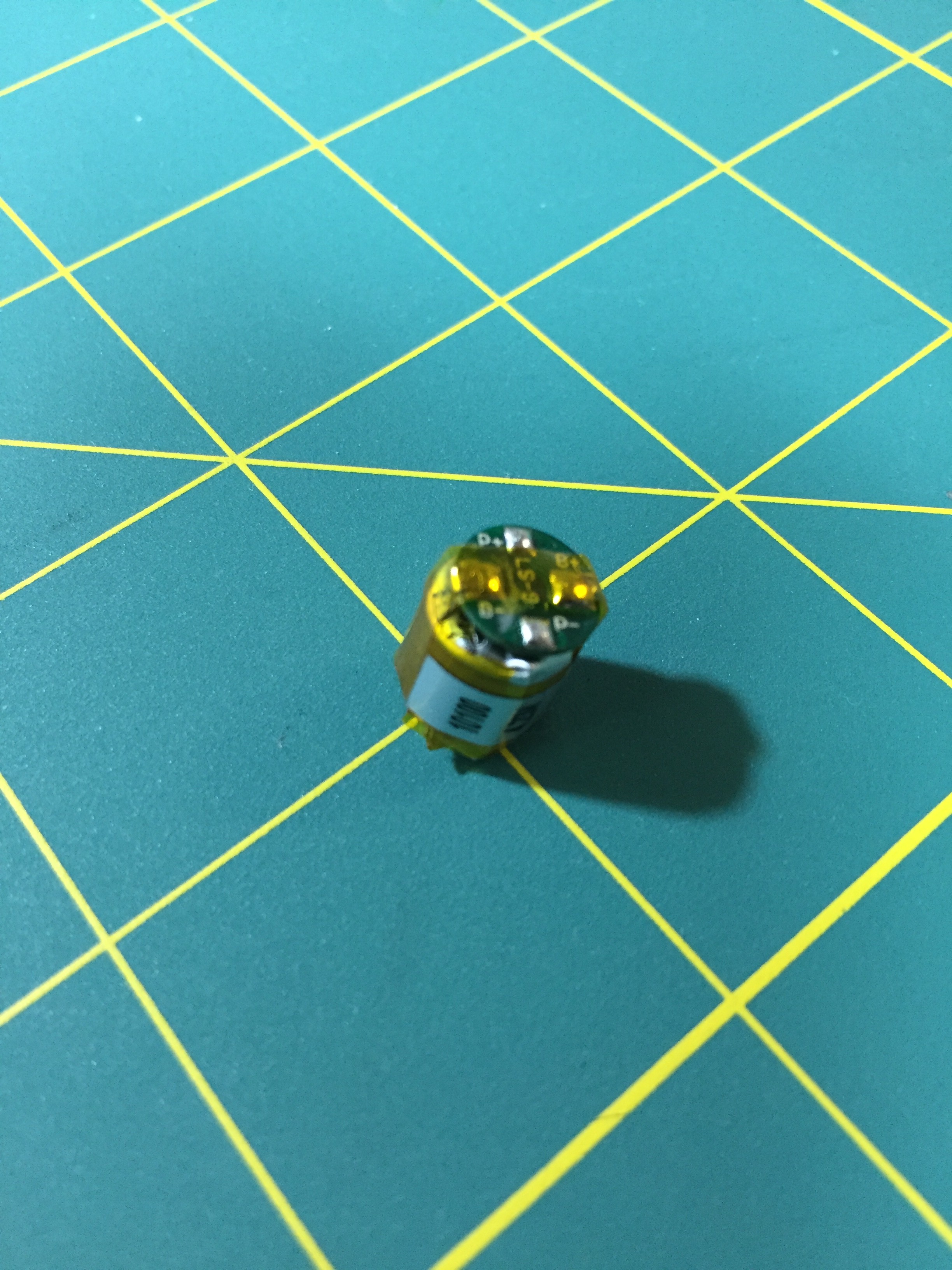
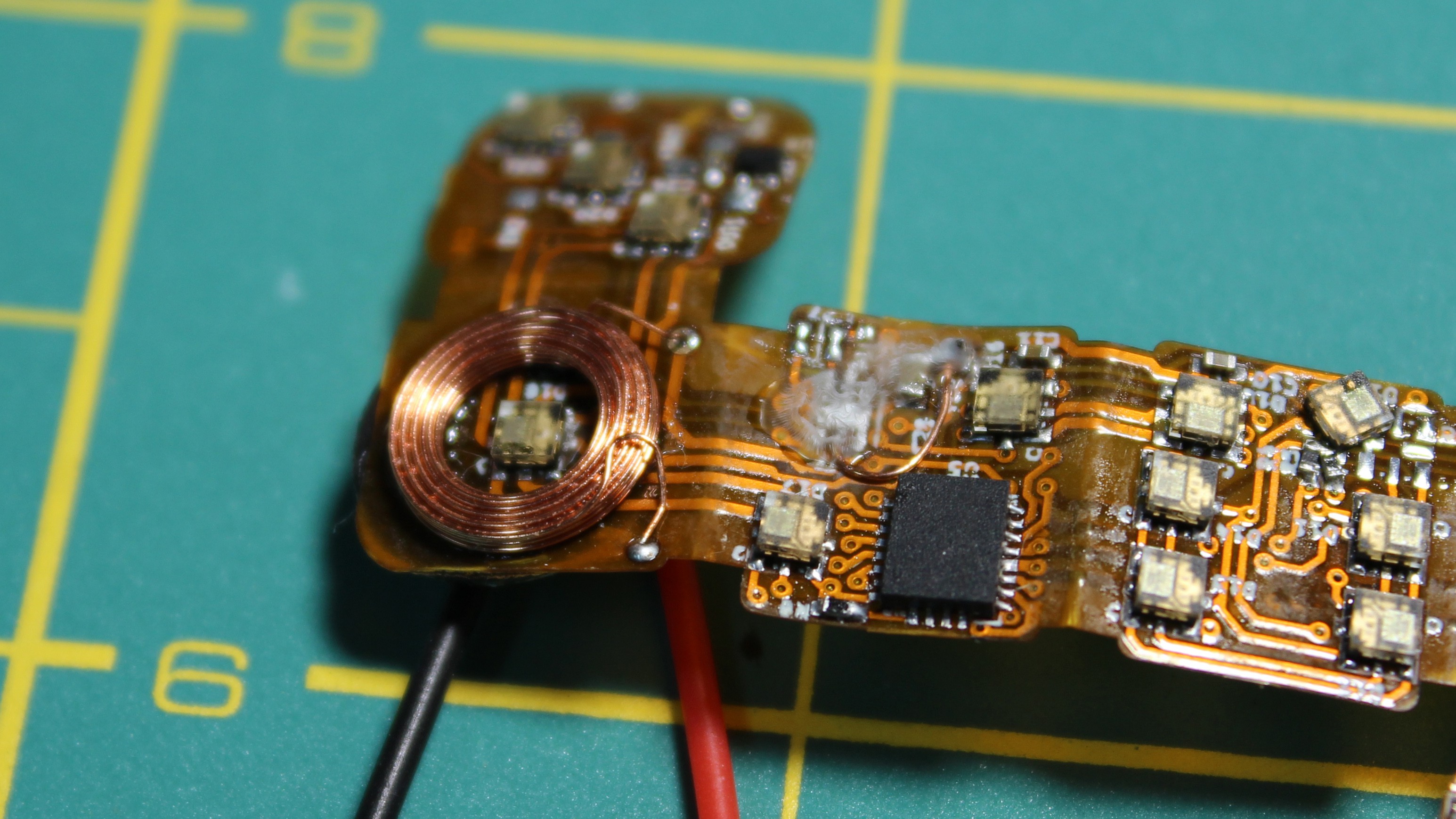
So, the principle is the same as with the last prototype. The components are soldered onto a flexible pcb, that is then folded and placed inside the case, with the LEDs facing outward. The battery fits in the middle and then the top flap folds back in to finish the cube. This small panel here was made using GoldPhoenix batch flex service.
The main microcontroller is again the Simblee, internally it is just an nrf51, crystal and chip antenna in a single package. Now, while the simblee has been really useful to get up and running, they provide an arduino-compatible toolchain and libraries that make writing your first bluetooth program a breeze, I think for the next version I’ll actually switch directly to a nordic chip (the nrf51 or nrf52). RFDigital, the creators of Simblee, was acquired by somebody else, and ever since, support has been really lacking. Plus the chips are unreasonably expensive for any sort of batch manufacturing.
LEDs
The leds are APA102 2020. These little guys are really great. The colors are amazing and they are very easy to control. They are also really simple to connect, as they are meant to be daisy chained. This turned out to be a huge advantage, as it reduced the complexity of the routing. In order to get affordable flex pcbs, you really need to stick to two layers, and with my size constraints, not having to route a complicated led matrix really helped! Of course, APA102s are a little more expensive than similar ‘dumb’ RGB leds, but thanks to Alibaba, I was able to find some for a decent price.
Now there are two issues with the APA 102s, or at least the ones I got.
The first one was that they draw a full milliamp of current even when off. I think what’s happening is that the internal PWMs that modulate the intensity are just ‘dumb’ and remain on all the time even if the intensity is 0. But with 21 leds, it means that the dice would constantly draw 21 mA from the battery, which would kill it in 2 to 3 hours for sure. To remedy this, I added a small transistor to cut off the power to the LEDs altogether, and had the microcontroller toggle that transistor when it went to sleep.
Unfortunately that was NOT enough. This one stumped me for a bit, but the best I can explain it is that the LEDs will drain current from the data and clock lines. So in order to make sure the LEDs don’t draw any leakage current, I had to make sure the data and clock lines were low before going to sleep.
Eventually though, I was able to get the current draw down. I still think there is some work to be done to minimize the current wasted in pull ups and pull downs in other areas of the circuit, but again, for this prototype this was good enough!
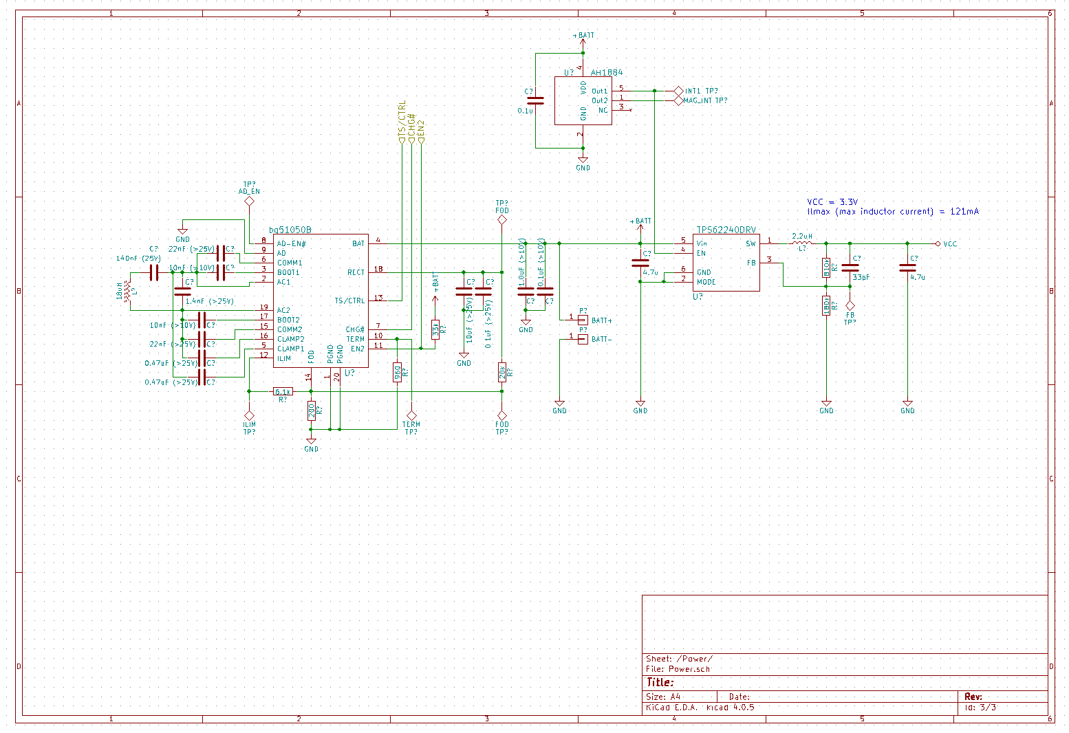
Power Circuitry
For power regulation, I was planning to use a small buck converter to get the Lipo voltage down to 3.3V, but ended up having stability issues (that I still haven’t quite sorted out) and ended up just ripping out the whole thing and powering the microcontroller directly from the Lipo battery. It is technically slightly outside the recommended range but it seemed to work, at least for a prototype.
The last IC on the board is the magnetic switch. The idea was to insert magnets in the dice’s carrying case, so that they would turn off while being transported. You don’t want the dice to light up and drain their battery for no reason. I had the magnetic switch connected to the power buck converter, so that it would turn off all the logic whenever a magnet was present. Unfortunately, turning off the power means that the LED control lines become floating, which, in turn causes the LEDs to turn on to arbitrary colors. Not acceptable…
So what I ended up doing was wire the output of the magnetic sensor to the microcontroller instead, and handle the ‘don’t turn leds on’ through software. It’s not as elegant a solution, but it did the trick. The magnet triggers an interrupt that in turn causes the micro to turn the led power off, set the control lines low and go to sleep.
I think that covers all of the internals! Let’s look at the design and assembly some more.
Fit Up
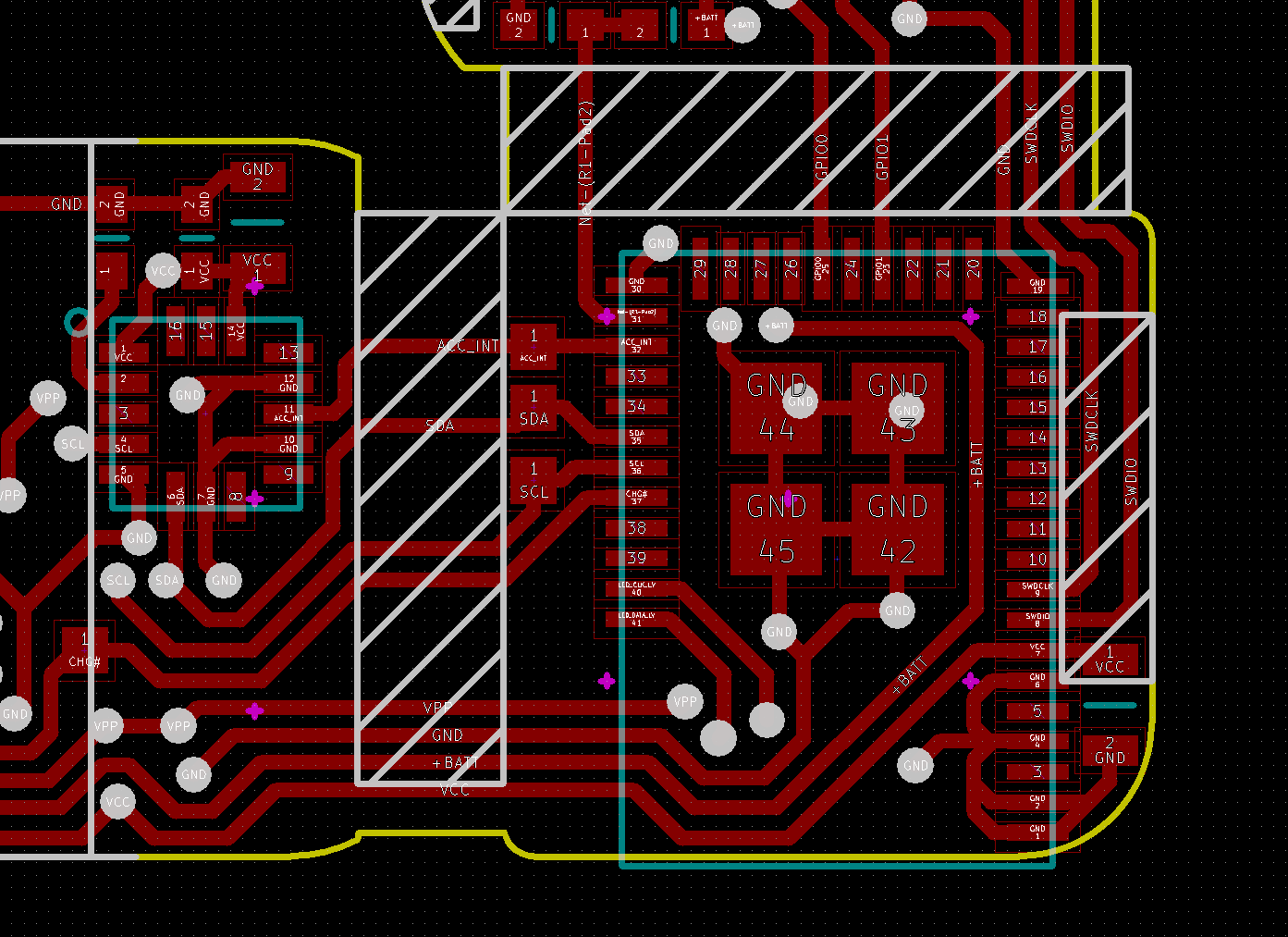
Unsurprisingly, for this next revision of the dice, I restarted the design from scratch. I wanted the dice to be exactly 16mm and have much more rounded corners. Well, you won’t be surprised to hear that it made the layout of the board quite challenging. Even though the leds are daisy chained, connecting all of them is slightly more complicated than I made it seem with the schematic. In the schematic it looks like there are only two wires going between each led, but of course, that’s ignoring power and ground. And unfortunately, the power and ground pins are not quite as conveniently placed that you can just connect 4 pins to 4 pins.
The other complication was that the board gets bent, and, aside from the obvious fact that I couldn’t put any component in the bends, the bends themselves put an extra amount of stress on the copper traces running through it, especially if you have a pad near a bend. The chances of causing a crack in the copper are really high. But, I didn’t really have a choice, the leds are pretty big and the dice really small.
So I tried to keep the traces going in the direction of the bend. I couldn’t, however, keep pads away from the bends, there just wasn’t room.
Annnd, of course, that did turn out to be a significant problem. I had a ton of boards start failing once I bent them to fit inside the case. Eventually I put together a small bending jig and tried to stress the boards as little as possible. That meant solder and test and program everything with the board flat, then bending the board with the jig, trying to concentrate the bend in the ‘safe’ areas, wire up the battery and drop the whole thing in the case in as fast a motion as possible.
To be honest, my success rate was pretty low, and when each board take around 4 hours to hand-solder and assemble, it’s pretty soul-crushing to have it just stop working on the next to last step. The worst part when that happened was that any attempt to get the board back out to try and fix the traces would inevitably cause stresses in another spot and cause some other crack to appear. Needless to say that this I will need to spend some time finding a proper solution to this problem, but anyway, obviously I did manage to get some of the boards fully assembled and working.
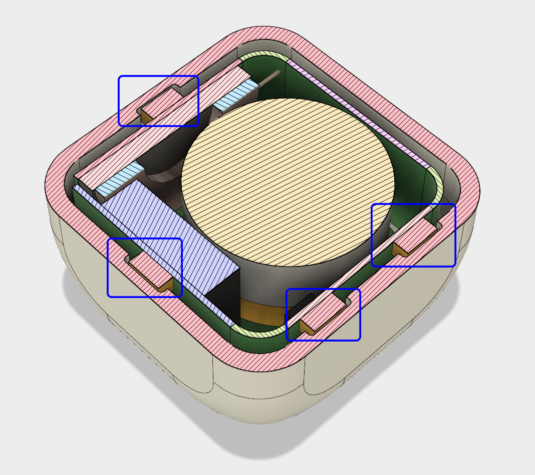
Inductive Charging
Remember when I mentioned scaling down the inductive coils for the charging circuit, and specifically how the coils needed to be much closer than with traditional Qi chargers? So yeah, it turns out that the only way to get the coils close enough together was to move the receiver coil all the way up against the case. Actually, even closer, I had to make a pocket so that the coil would be 0.5mm from the outside plane.
Of course that’s all fine and good except I still need at least one LED on each side, including the side with the coil. And to make everything even more complicated, the coil needs to have a ferrite backing, to focus the magnetic flux as much as possible…
As it turned out, I got lucky, the APA102 led can fit inside the coil, and it wasn’t *too* annoying to pull the ferrite backing off the coil so I could glue it to the other side of the pcb.
Epoxy
The very last step in assembling the dice, is to pot the entire thing in epoxy! This is a very simple thing, but it makes an enormous difference. I’m pretty pleased with the idea! Potting everything in epoxy serves many purposes at once. First, it keeps me from having to use fasteners to hold everything together. Then it makes sure that nothing moves around, which is a pretty big deal considering how fragile the flexible pcb. But that also gives the dice a really, really solid feel.
And that is probably the most underrated feature of this prototype. When you hold it in your hand, you can’t tell that it’s full of electronics, it just feel like a regular dice. You can even hear it when I roll it. The previous prototype sounds all rattle-y, whereas this new one sounds correct.
The third purpose of potting everything in epoxy is that it evens out the density, and makes the dice much more balanced. Of course, the density of epoxy isn’t exactly the same as the density of a lipo battery, or the pcb or the components, but it is much much closer to those than air. And so, by filling in all the gaps, the difference in density really decreases.
In fact, I haven’t done it yet, but I’m pretty sure I can make up the last remaining delta by adding a bit of lead here and there inside the case before filling it. And the best part is that because the dice can record every single throw, I can collect accurate statistics on how unbalanced it is and correct for it in the next prototype!
Voila!
But there you have it, that’s how the dice is put together! And while there are clearly still a lot of issues with it, I’m pretty pleased with the result.
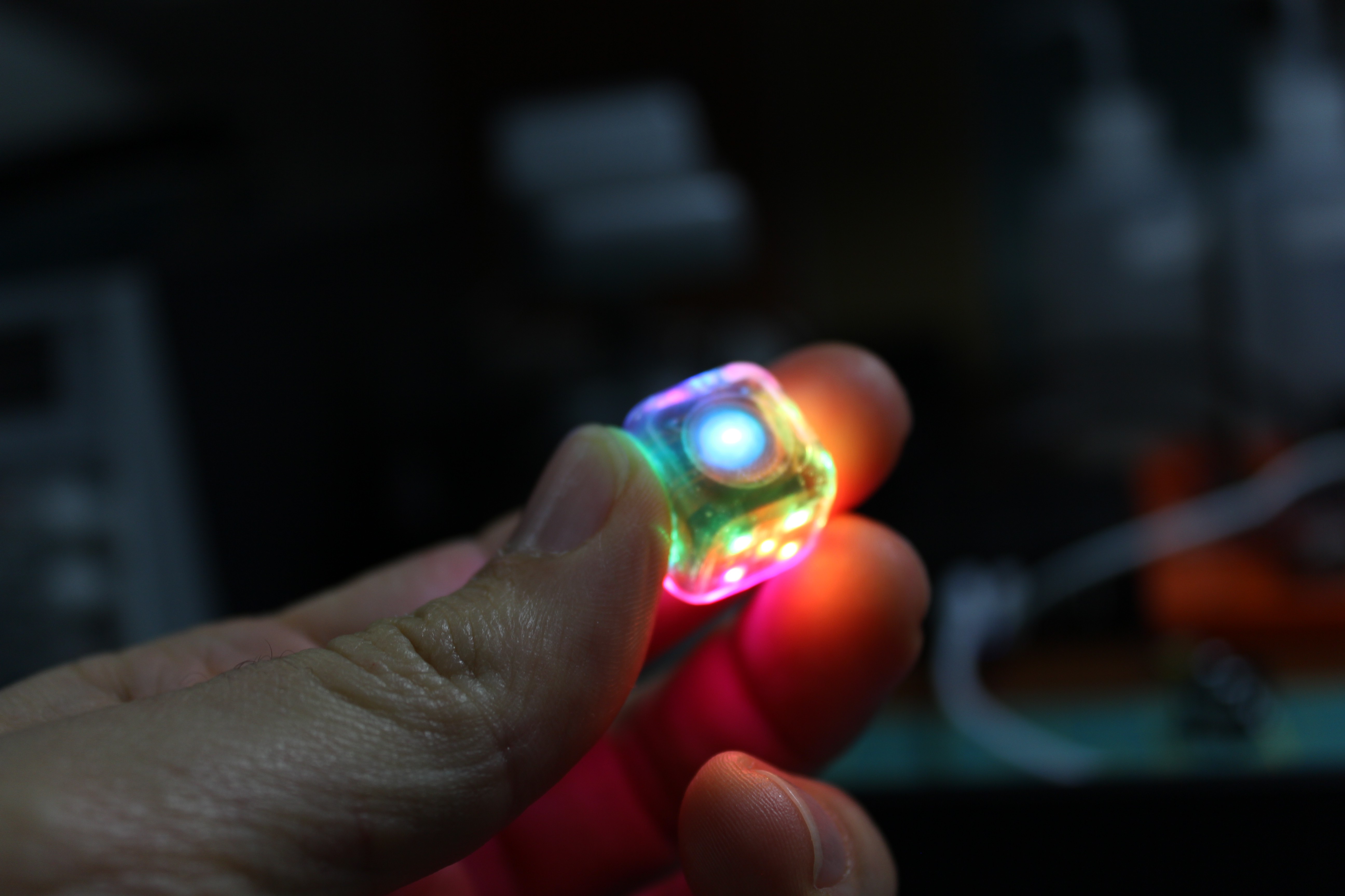
I finally finished the second board for the Dice, the full RGB one this time! It's pretty awesome already! I don't have a flexible PCB version yet, but this here is a prototype board.
Those APA102 2x2mm look really awesome!
---------- more ----------
Of course I had to make a few changes to the schematics and the case design. For starters, I replaced the Linear voltage regulator with a switching one. Switching voltage regulators are much more efficient than linear ones (which end up mostly dissipating the voltage difference between the input and the output as heat) but they require a few more supports components, not least of which is a decent inductor.
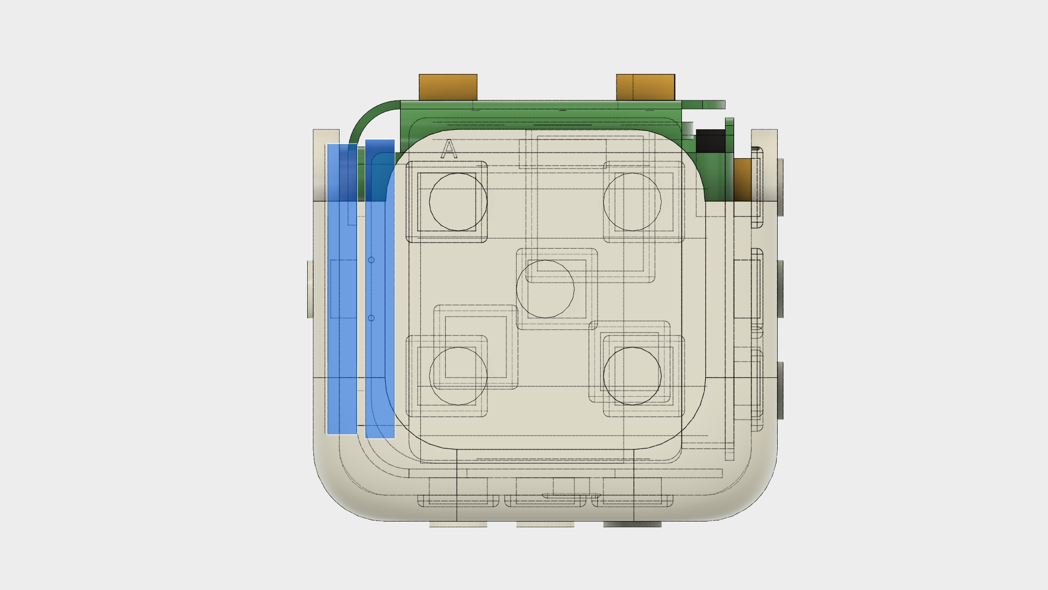
Fitting all the components inside the case was also another level of Tetris mastery. The reduced size combined with the more aggressively rounded corners left me with very little room to fit everything. At this scale, even deciding where to put the folds is a major consideration, as a 1mm or 2mm bending radius will mean that that edge of the board can't be as long and there won't be as much room for components. In fact, fitting the Simblee chip on the board was almost impossible.
(The hatched areas are either bends or another component poking through to this face)
Then, of course, there are the APA102s. Because these are typically 5V devices, I wasn't sure if they would accept a 3.3v logic level. I knew they could be run on 3.7v, there is evidence of that all over websites like Adafruit, but I wasn't sure about 3.3v logic... In the end, I found out that they work just fine. They are, relatively speaking, huge though. Compared to the previous LEDs (that used a 0603 footprint) they are really thick, an ENTIRE MILLIMETER! :) I laugh, but at my scale, I couldn't afford to pull the PCBs inward any more, and so I had to make cutouts in the case to accomodate the LEDs.
Eventually I submitted a new prototype board to my favorite PCB house, Oshpark. The board came back, and I proceeded to try and assemble it by hand. It's funny, after you've soldered a bunch of 0402 resistors, a 0603 looks positively huge! :) I used a combination of techniques to do this, sometimes applying a bit of solder paste over all the pads, and then letting the solder flow to the chip pins as I heat it. It works surprisingly well.
I made a few bozo mistakes of course, most notably on the APA102 footprint and regulating inductor. First I dimensioned the regulator for a 2.2nH instead of the required 2.2uH, only 1000 times too small :)
The APA102s were somehow completely wrong, but in a rare stroke of luck, I was able to get them connected correctly by rotating them 180 degrees and flipping the clock and data pins. So, so lucky, but then again, that's exactly why I made a prototype board before sinking a bunch of money into flexible PCBs. But hey, they work, and OMG they look so nice. I can't wait to get the final boards made. I did notice a couple things in the process though.
The first is that the actual LED elements (the R, G and B) are not actually centered on the chip, but offset to one side.
This means that if I want the light to be correctly in front of the number dots, I'll need to shift the component positions slightly here and there. Of course because space is so limited, that in turns means that there are certain component orientations that I can't support, specifically next to the bends in the PCB.
The other is related to the fact that I power the LEDs directly from the battery in order to keep their supply voltage as high as possible (3.8v instead of the logic 3.3v of the rest of the board). It works great, except that it means the LEDs are CONSTANTLY powered, even if they are not technically turned ON. This has 2 side effects. The first is that they unnecessarily draw a little bit of current even when the die is supposed to go to sleep, which is no good for battery life of course. The second is that sometimes, if a LED is powered but not 'initialized' properly, it may decide to turn ON! That's really not cool because it means that when I try to forcibly 'turn the die off' with a magnet, the LEDs may just stay on forever...
Fortunately, that's something we can fix with a very-low-dropout transistor! In fact the same magnetic switch that will turn the voltage regulator off will now also turn off the power to the leds. Great!
Wireless charging is still a bit tricky too. Since I picked a chip that follows the Qi standard, I thought I'd be able to use an off-the-shelf charger, which would be great moving forward. Unfortunately, at first it just didn't work. Poking through the different signals with my scope, I finally figured out that the voltage on the receiver coil just wasn't high enough to turn the chip on. I replaced the coil with a much larger one, stolen from a known working receiver I bought from Adafruit, and low and behold, the connection worked! The problem was obviously a poor coupling between the two coils, which in a way made sense. The transmitter coil was so much bigger than the receiver that most of the magnetic flux was wasted.
Looking for a solution, I stumbled upon an application note from Wurth that specifies which transmitter coils work best with which receivers, and guess what? The transmitter coils compatible with my receiver are way smaller than the one in this charger! I now have some new coils coming in the mail so I can try a few different combinations and see what works best!
In the interim, I tried replacing the transmitter coil with one of my receiver coils, and it sort of works. The two coils (transmitter and receiver) have to be very, very close together to get a good enough power transfer to start the charging circuitry, but it works. Here's hoping that the proper matching coils makes it that transfer works from a few millimeters aways, that's all I need really!
Finally, I've been testing out if and how I can paint the cases. The difficult part is that I need a way to leave unpainted areas in front of the LEDs. It looks really nice when only the dots light up, not the entire plastic case. I imagine I'll probably make a hundred or so dice in this next batch, so that I can have some for other people to develop for, and so I don't really see myself painstakingly hand painting each die like a miniature. I need a process that is fairly fast, accurate and repeatable. What I've settled on, although it needs a bit of refining, is to print the cases with raises number dots. That way I can paint over the entire thing and then sand the face back down such that the dots are transparent again. I am still sorting out how many layers of paint I need, as well as what kind of paint to use in the first place, but I think I'll get there. Here is a test that mostly worked out!
So as you can see, things are moving along. There is still a lot of work to be done, of course. I think I'll pretty soon need to make a carrying case that will double up as a charger, sine it looks like off-the-shelf chargers won't quite work. That will be another whole thing, of course!
And obviously, I still need to create a GOOD game that takes advantage of the dice :) With the RGB dice coming soon, I am thinking of something centered around elements (fire, water, earth, etc...), where each die represent an element, and you pick and roll the dice you want to cast spells to defeat monsters. It'll be fun!
Following a suggestion from a commenter on youtube, I was able to find a lipo battery small enough to fit in the dice! I received samples early this week, very exciting!
I got so excited to start seeing if I could make the next version only 16mm wide that I started working on the schematics and now 3D CAD. That's just as well, since now I can get prototype boards made while I continue to work on the firmware.
---------- more ----------
Oh and I'm going to try and integrate wireless charging! Not only is it really cool, it'll allow me to never have to open the case (assuming I get over-the-air programming to work), in turn meaning I'll be able to just pot everything down and glue the case shut (no more screws).
I'm trying to stream my work as much as possible. So don't hesitate to follow me so you get notified! http://twitch.tv/jean_simonet/
I put together a shorter video, less technical and more like a sizzle-reel.
Hopefully I can get back to work soon! Taking pictures and editing stuff together, let alone re-recording stuff a gazillion times, ends up sucking up soooo much time...
 Jean Simonet
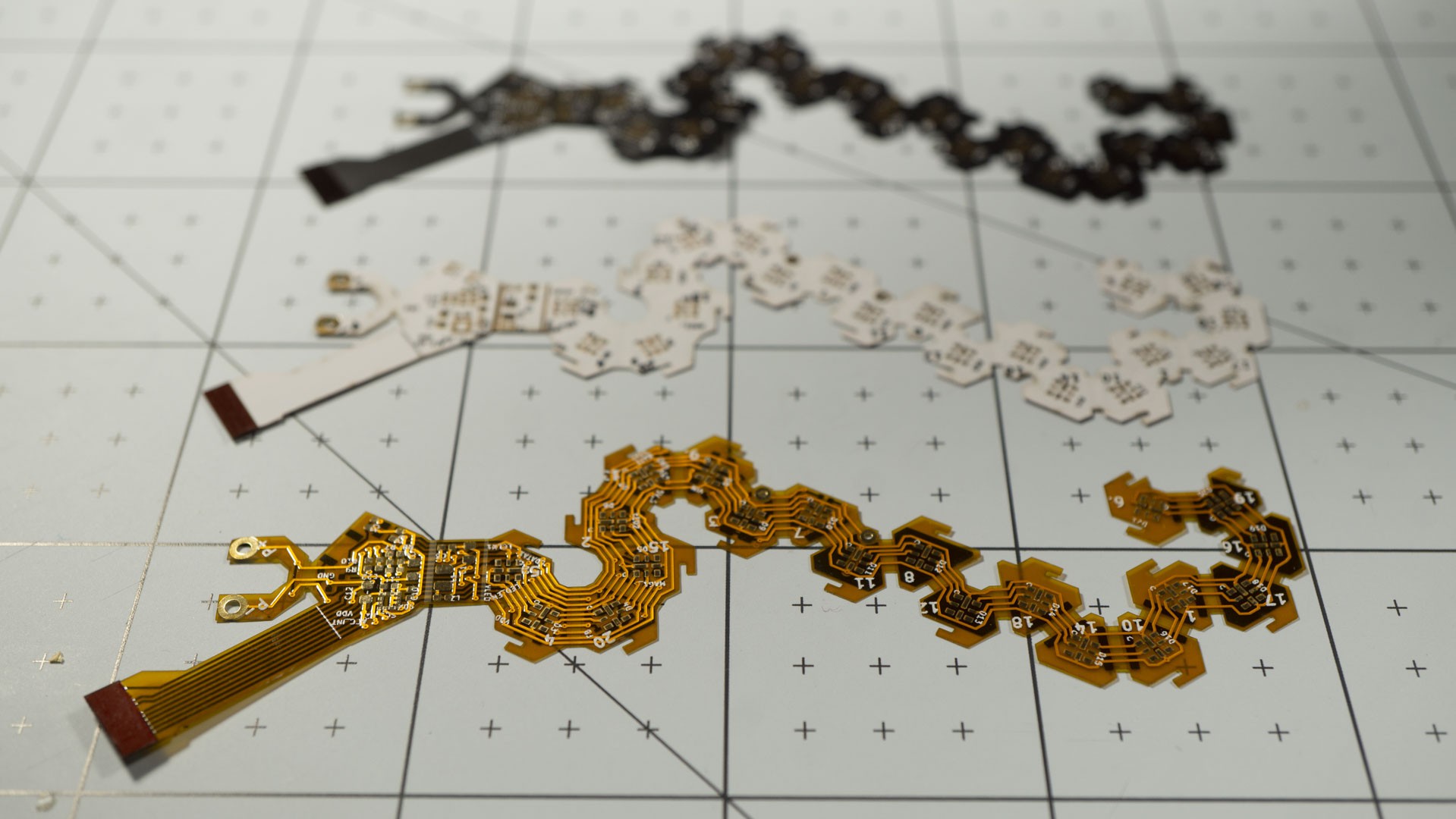


 And that is probably the most underrated feature of this prototype. When you hold it in your hand, you can’t tell that it’s full of electronics, it just feel like a regular dice. You can even hear it when I roll it. The previous prototype sounds all rattle-y, whereas this new one sounds correct.
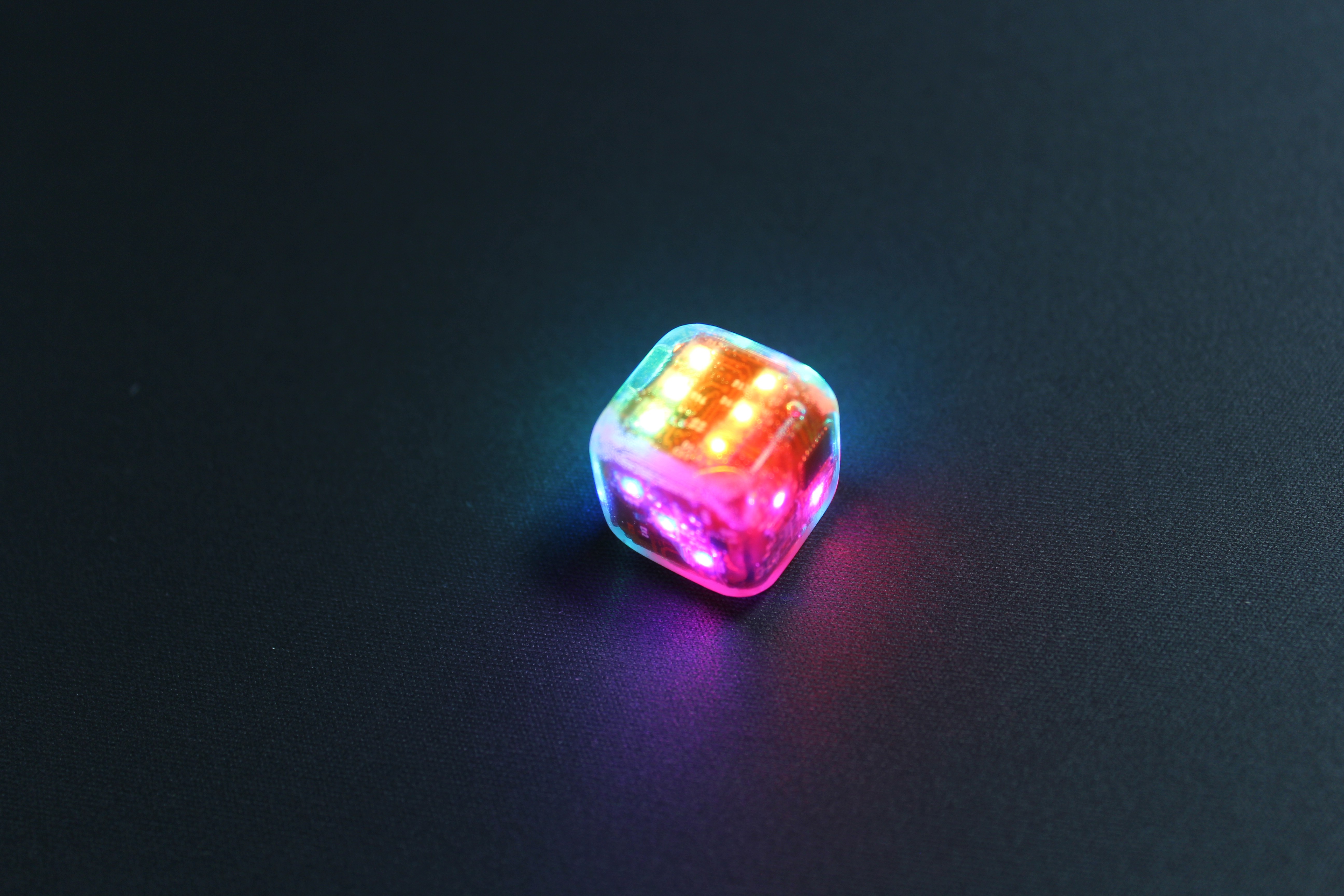
 Those APA102 2x2mm look really awesome!
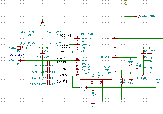


")