-
Lights are shining again
01/25/2018 at 11:15 • 0 commentsAfter almost giving up on the analog version of this project, I decided to ask my friend Grega for help. It turned out to be a good idea, since we've come up with a simple proof of concept that works well.
I thought this should be simple and it is. In theory, if you add sine wave signal to a constant voltage you should get the result I was looking for. Right?
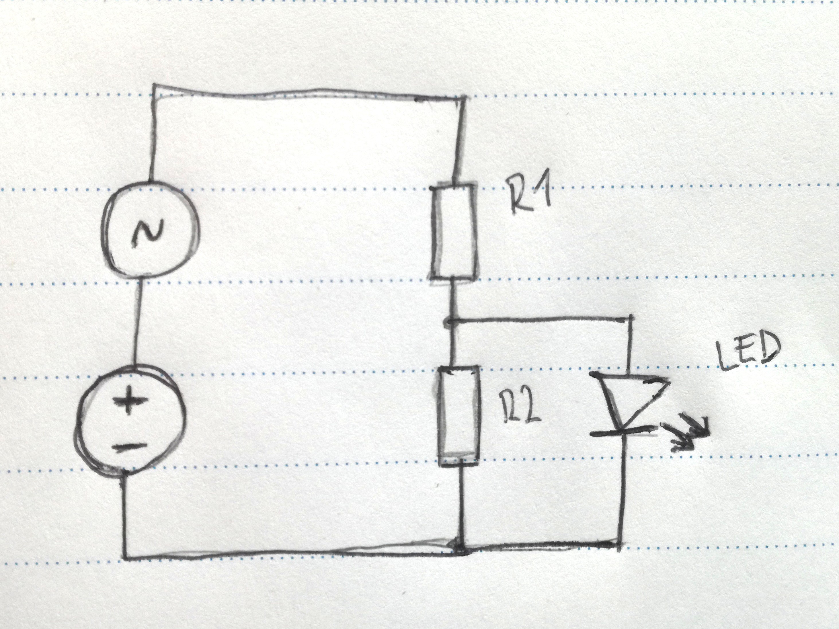
![Concept Concept]()
Concept We got the sine wave output from a smartphone function generator app, via headphones output. I would never think if it by myself- and it works great! I don't know what is the voltage of the output of my smartphone, but I assume it's around 1V peak to peak. That said, I can play with different voltage divider values (to get the constant DC) and see what works best. I am testing this with a 9V battery, but will probably use coin cell battery later.
I'm using a 0.5Hz sine wave, 100% amplitude (how can I measure this?).
Here's the screenshot of my function generator (application):![Function generator settings Function generator settings]()
Function generator settings ![Circuit diagram Circuit diagram]()
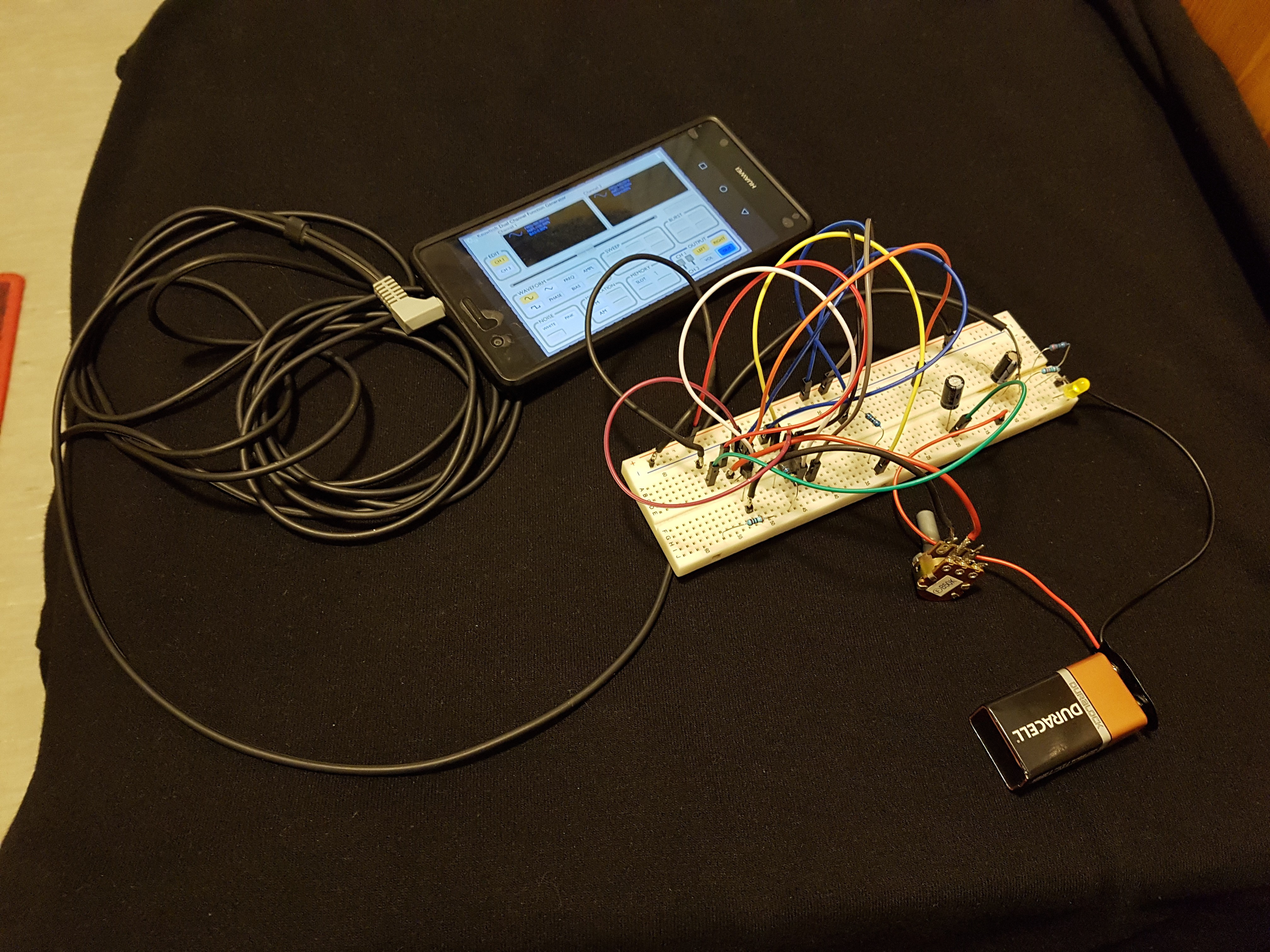
Circuit diagram ![How it looks altogether - nevermind the mess on the protoboard (only the right part of it is used here) How it looks altogether - nevermind the mess on the protoboard (only the right part of it is used here)]()
How it looks altogether - nevermind the mess on the protoboard (only the right part of it is used here)
White LED:For white LED, I set the voltage divider values to output 2.6V (with load). Without the load - with only a multimeter attached across R2- I got 2.9V.
R1= 10k
R2= 4kVout = 2.9V
Vled= 2.6V
Yellow LED:R1= 10k
R2= 3.3kVout = 2.3V
Vled = 1.8V
Red LED:* It's hard to focus the camera in dark, red color doesn't help either...*
R1 = 10k
R2 = 2.7kVout = 1.9V
Vled = 1.7V
ConclusionSo this works! I'm happy with the results, as I wanted a slow and subtle "waving" of LED brightness. Now I "only" have to figure out, how to make that sine wave thing somehow.
-
Giving up on theory
12/08/2017 at 18:08 • 0 commentsI decided to study the 555 fade in/out circuit, to understand its working and to take the control of the LED into my own hands...
I failed, realising I'm just a young padawan that has a lot yet to learn about electronics. Since I don't understand all the details (calculating the fade-in/fade-out times and the frequency and amount of "breathing" effect), I won't even try to explain the maths and current flows and everything. Whatever. It kinda works somehow. Meh.I also tried getting into the simulators, but couldn't make it work in EasyEDA neither in CircuitLabs (I didn't even try to get into the more professional spice stuff, I don't understand sh*t there...). Too bad I don't study EE :)
![]()
BUT! Theory shouldn't be an obstacle to the "hacker attidute and the hands-on imperative" (Steven Levy, Hackers: Heroes of the Computer Revolution), right? I mean it still glows up/down somehow and nobody will ever know what I really wanted to achieve. For artistic purposes and for version 0.1 (AND after three full afternoons of studying theory and wnb calculating stuff) it's good enough :)
With a red LED it works like this (I didn't want red, but okay):
And with a white LED it looks like this (added 2.4k resistor across the C and E terminals of the transistor, to lift the emmiter voltage a bit- suggested by @Bharbour ,tnx for the interest and the patience to explain things to me):
I ordered some low power 555 timers, some ATtiny microcontrollers and LDRs and phototransistors. And button batteries. Maybe I'll return to this theoretical study after I have some fun with microcontrollers, or after trying some other circuits or just adapting this one to work at 3v (for coin cells). I learned a lot from this: from some kind of very basic circuit analysis, to capacitor working (and important calculations), BJT transistors and their modes of operation, LEDs...
Now it's time to go back to more known territory of computer code and take a break from all this analog wizardry :'D
-
Teaching LEDs how to breathe
12/05/2017 at 13:25 • 0 commentsThere's tons of literature and tutorials about the 555-timer and it's applications. I thought I would use it in astable mode and change duty cycle, but then I found a circuit that was very close to what I need.
Examining the "Breathing LED circuit"
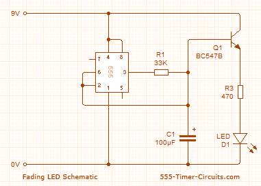
This circuit is fading the LED up and down, it looks simple and it doesn't use many components. Great!
But how doest it work? Can I modify it, so it won't turn all the way off?![UP/DOWN FADING LED Circuit UP/DOWN FADING LED Circuit]()
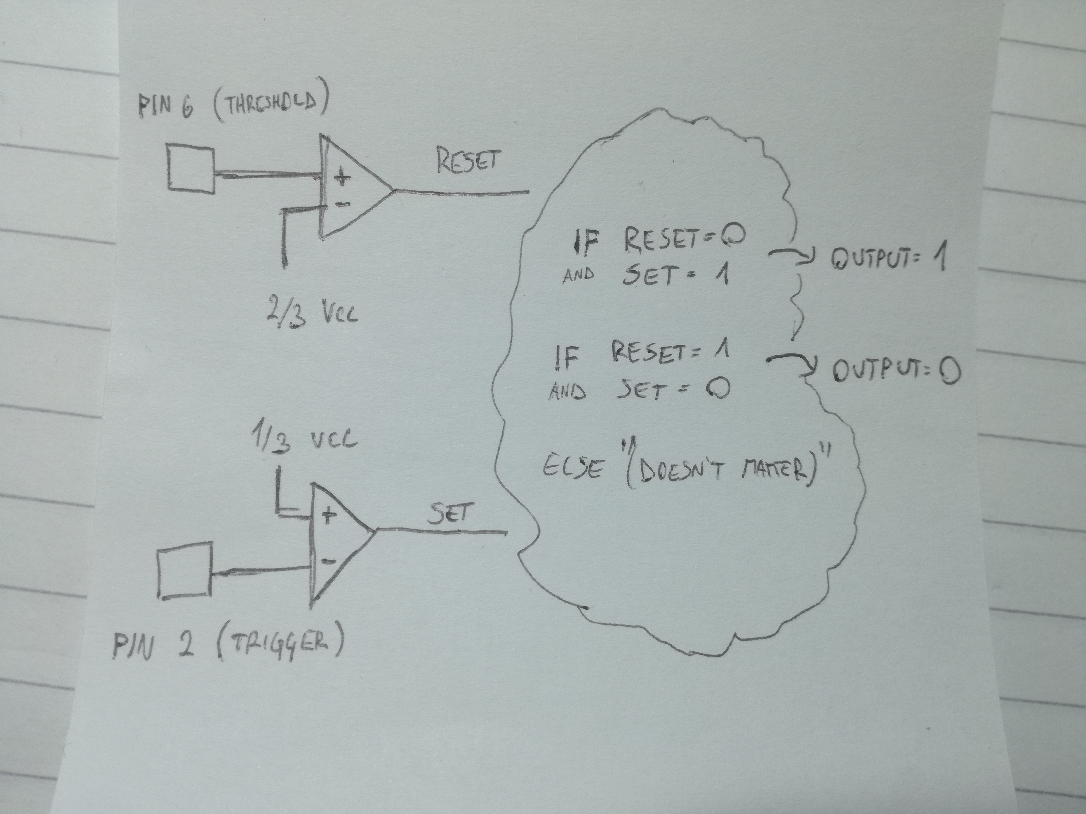
UP/DOWN FADING LED Circuit ![Inside of the 555-timer (heavily simplified) Inside of the 555-timer (heavily simplified)]()
Inside of the 555-timer (heavily simplified) I quickly noticed that this circuit doesn't use pin 7 (discharge), so it's probably not astable mode and it doesn't work like I imagined it would (changing PWMs duty cycle to dim the LED).
From what I understand it works like this: pins 2 (threshold) and 6 (trigger) are "monitoring" the voltage across the capacitor (C1). When the voltage is smaller than 1/3 Vcc (in our case 3V), pin 3 (output) will go HIGH. When the voltage gets above 2/3 Vcc (6V in our case) output will go LOW.
In the beginning, the 555s output will be HIGH (capacitor discharged, voltage < 1/3 Vcc) therefore charging the capacitor (increasing voltage drop across it). As capacitor charges, less and less current flows trough it, and more current goes to the base of the transistor. This increasing current entering transistor's base gets amplified and causes the LED to turn on slowly.
When the capacitor charges up to 2/3 Vcc (6V) the output will go LOW, and the capacitor will begin to discharge trough the transistor. It's output current will drop (exponentially?) with time, which means the LED will fade off slowly. When the capacitor gets below 2/3 Vcc the process repeats.
Getting the RC values right
Obviously, changing the values of the capacitor and the resistor will change the speed of flashing. I tried replacing the resistor (R1) with a 47k potentiometer. I played with it, trying out different capacitor values (from 100uF to 470uF) but I couldn't get the right result.In every case the LED was fading up/down nicely, but turning off completely. If I cranked up the resistance, I could keep the LED on all the time, but then it wouldn't fade down at all (or really just a little bit, barely visible and too fast).
I guess I should dive deeper into the working of the transistor and start calculating things. Any hints or ideas how to figure this out? Is it even possible to achieve this kind of fading upd/down (but never turning it off completely) with this configuration?
-
Hello world!
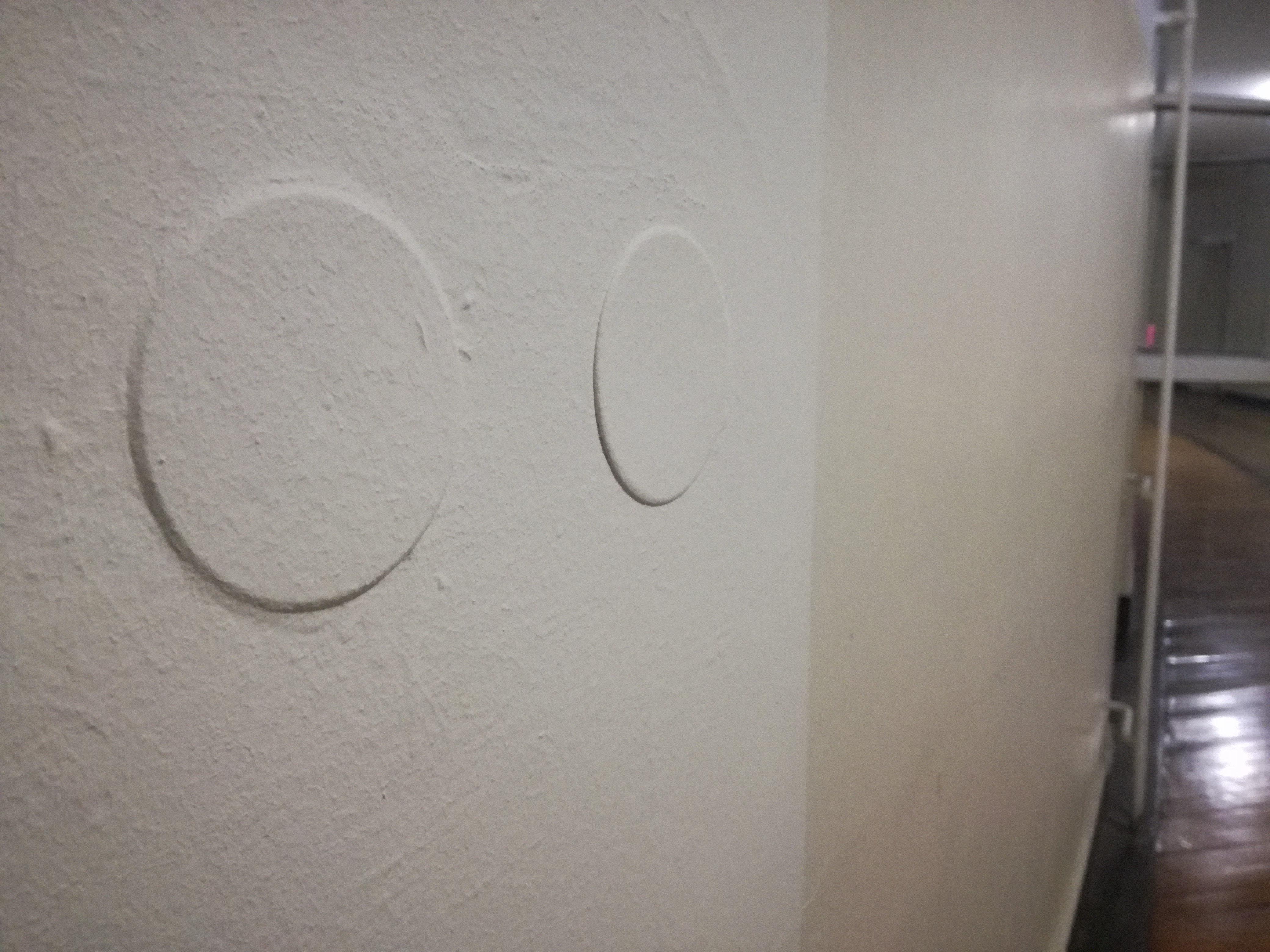
12/04/2017 at 21:50 • 0 commentsMy original idea was to build the "LED candles" in 1-2 days and place them all over my student's dorm hallway. It would look cool at night , since we have long and dark hallways. It would be cool to put them in theese covered holes in the wall (what's the right word for theese?), they are all over the place.
![Hole covers on the walls Hole covers on the walls]()
Hole covers on the walls As a beginner in electronics, I tought it was a cool 1-2 day project to learn some basics. While It turned out to be great for learning, it wasn't a 2 day project :'( (of course, I never estimate the time needed right).
I'll first do the right-kind-of-glowing and later I'll focus on the light sensor part.
I guessed I'd need a LED, battery, capacitors and some resistors. And I had "RC-circuit" and "RLC- circuit" keywords in my mind, but didn't know much about it. After some time googling for some already-made implementations of my idea (combining keywords LED and glowing, flashing, fading, fire, candle... ) I figured out it would be the best to use the famous 555-timer (I actually had some at home). All the analog variants used too many components. Oh and, the best keyword for what I wanted was "Breathing LED" :)
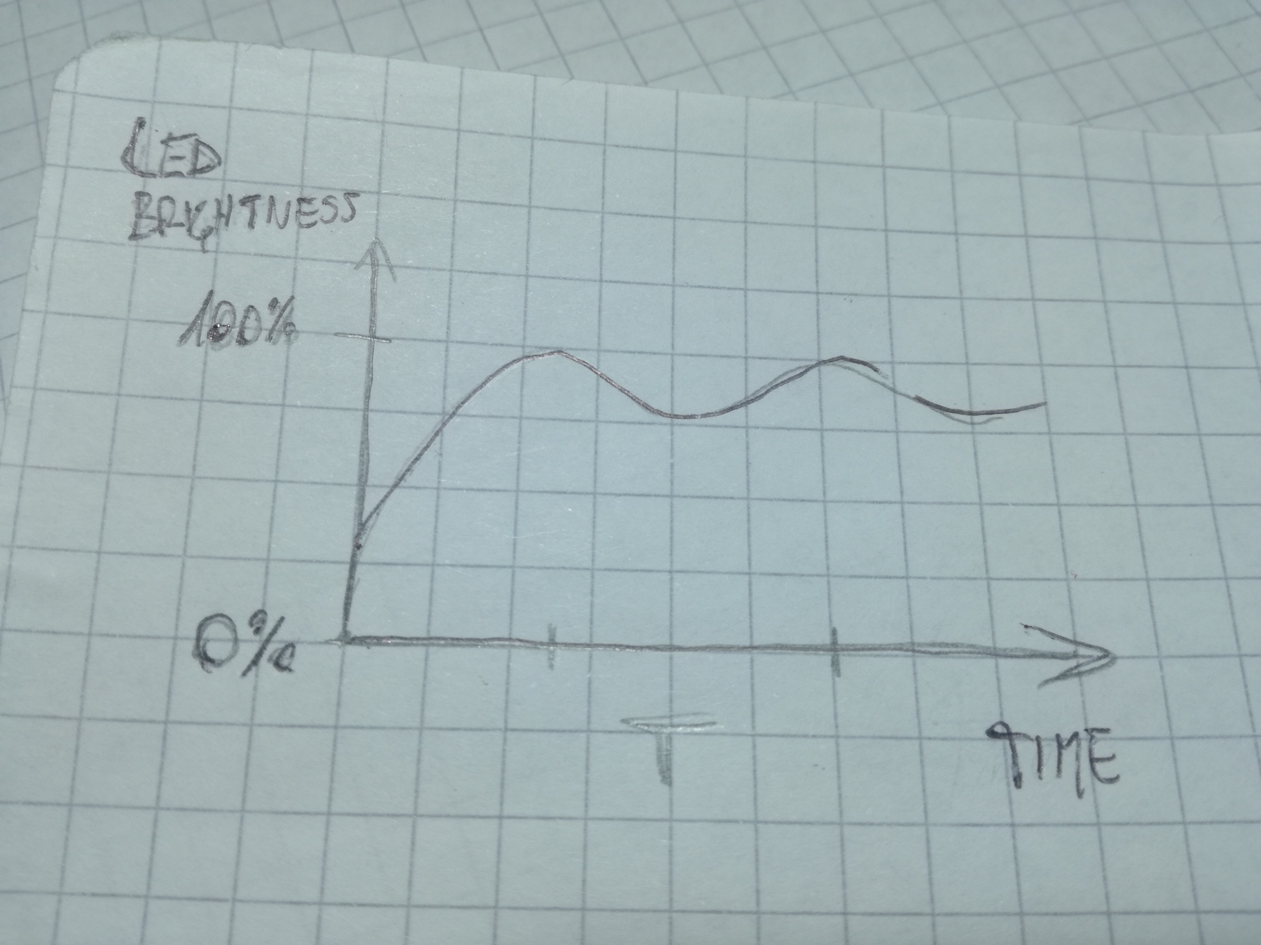
But nobody did exactly what I imagined. All the variants fade the LEDs on and off completely, while I wanted them to be turned on constantly with a subtle up/down fading effect.
![The "glow" that I want The "glow" that I want]()
The "glow" that I want - I don't want it to turn off completely. And it should be slow, like T >= 1second How would you do it?
Guerilla LED Candles
Simple, candle-like glowing LEDs that only turn on at night. Trying to make it cheap and use what I have at home.
 jurc192

