Andy Smith
-
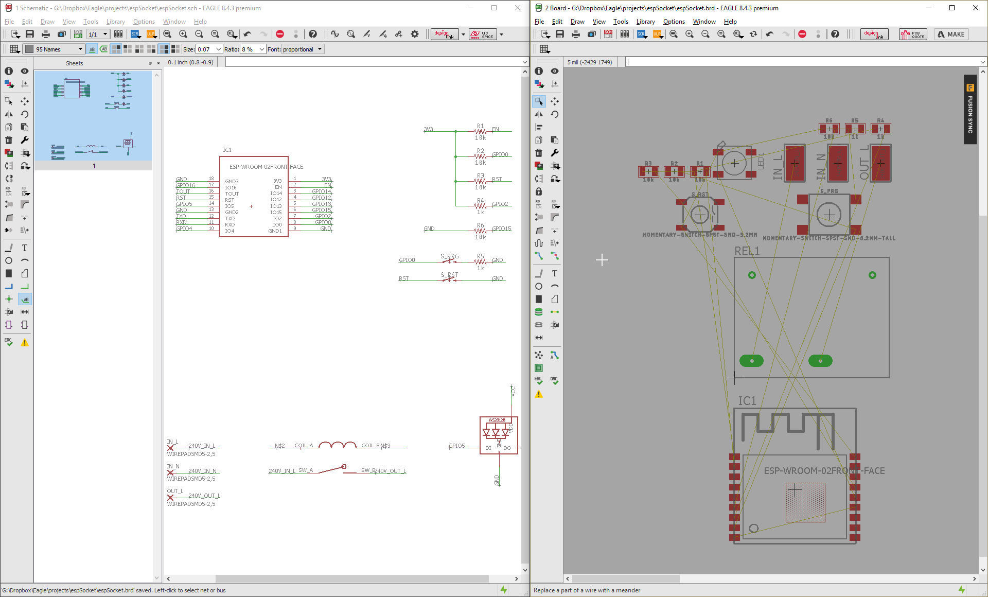
Schematic Part 1
12/06/2017 at 01:39 • 0 commentsQuick update - began the schematic in EAGLE tonight. I had to create a custom part for the Omron G5CA relay. This features 2x0.4mm elliptical pins for the switch contacts. I drew these up using oversized rectangular pads and added a wire to the milling layer, but I may change this to a 2mm round hole as the results may be more predictable from the cut price Chinese board manufacturers.
I also started the schematic for the esp8266. It's been a while since I worked with a bare module (boards like the NodeMCU and Wemos D1 have made things very easy), so I was drawing this up whilst breadboarding and testing in parallel. Took me a while to work out which pins needed pull-ups and pull-downs and how to get it to boot into flashing mode. I still need to make a final decision on which IO pins I'll be using for the LED, relay and button.
Still to do - power supplies (230V > 5V and 5V > 3.3V) and programming headers.
![]()
-
Part selection and layout sketch
11/30/2017 at 11:55 • 0 commentsAC-DC Power Supply
I anticipate the biggest space-eater on the board to be the power supply. Now, I am by no means an electrical engineer and I have never designed a board that interfaces with 230V AC before, so to do this safely I looked for the most self-contained solution I could find.
That's when I stumbled across the HLK-PM01 (datasheet) and a series of very useful blog posts about how to implement it safely. The part takes a 230V AC input and supplies 5V DC up to 600mA, with minimal extra parts. It's a fairly bulky component, but at 34x24mm and 15mm height, it will just about fit in the bottom recess under the board with just under 2mm to spare.
As recommended by Skippy's blog posts, I'm going to add a varistor and fuse to the AC input. On the output side, hopefully a pair of 0.1uF and 10uF smoothing capacitors will provide a clean enough output to the low voltage side.
There are some concerns with emissions, but as I'm not developing this into an actual product, I'm not going to worry too much about this. I may revisit this if there are any wireless performance issues with the ESP8266.
Final note on this: it's a 5V power supply and the ESP8266 is a 3.3V board, but having both 5V and 3.3V available (via a linear regulator) on the board will give me more options later for part selection.
Relay
This one required a bit of searching to find something low-profile enough to fit where the housing tapers off to 13mm underneath the board in the middle. A common, cheap part that I was planning to use (the GHI SRD-05VDC-SL-C) has a height of 15mm.
I found the Omron G5CA-1A, a 10A @ 250VAC rated relay clocking in at a svelte 11mm height. This is also a normally open contact without a normally closed terminal, which should make the high current traces on the board easier to route (the common contact pin on the SRD-05VDC is nestled in between the two coil pins).
Sketch
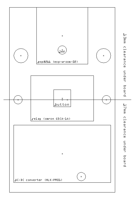
With the two largest components in place, I started doing some accurate measurements on the board and began the CAD layout.
![]() ---------- more ----------
---------- more ----------On here I have marked the 4 holes on the board, the support standoff (currently under the power supply - this will have to go!), and the point where the space in the housing drops from 17mm to 13mm.
There are two components that will need to go in the same position on the board - the button and the LED - in order to match up with the outer casing. I was planning to use the same through-hole components for both, but as I'm mounting components under the board I will need to re-think this.
I found a suitable surface mount button that crucially has the same height as the through-hole component on the original board. (4.3mm)
The LED was a bit of a problem. The original board uses a 3mm through-hole LED that extends 10mm from the top of the board and pokes through the top casing. I considered placing some surface-mount pads and using the same part (bending the legs), but had a better idea. I'm going to use some 3mm acrylic rod to create a light pipe down to the board, and use a surface mount RGB LED. Having an RGB LED will allow for different status messages (e.g. indicators for switch on/off, failure to connect to WiFI etc).
I'll use a WS2812B for the LED. It will allow for control from a single microcontroller pin, and reduce additional passive components required (current limiting resistors) and traces on the board.
Microcontroller
I was planning to use the very common and very cheap ESP-12E module, but it's a few mm too long to fit on the board. I'm instead opting for the ESP-WROOM-02, a slightly smaller module. It doesn't have as many GPIO pins broken out as the ESP-12E, but that's not really a concern for this project. It's not quite as cheap and widely available, but I've found them for $2.70 a piece on Aliexpress.
In the next update I'll begin the PCB schematic in Eagle.
-
What's it going to be?
11/29/2017 at 22:03 • 0 commentsMy goal is to design a drop-in replacement PCB that will fit into the six 'Status' branded sockets I have.
It will need to contain the following components:
- An esp8266 module with integrated WiFi antenna such as the ESP-12E. This is a nice and compact module with a surface mount design that required relatively few additional components.
- A relay rated for at least 10 amps at 230V
- An AC-DC power supply for supplying power to the esp8266 and relay. The it needs to be able to sustain up to 300mA for the esp, and comfortably another 100mA for the relay coil.
- A button for toggling the state of the switch
- A status LED
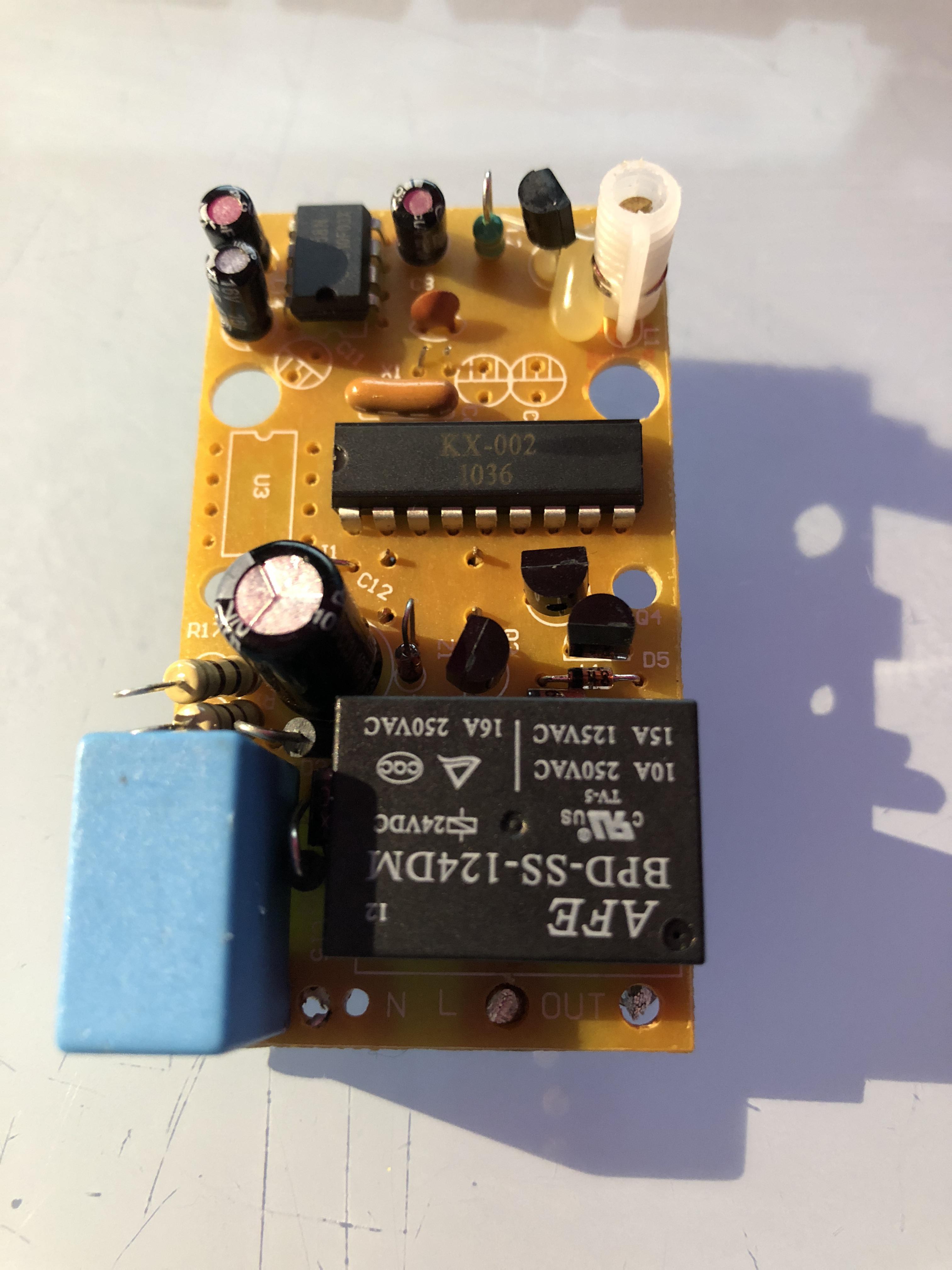
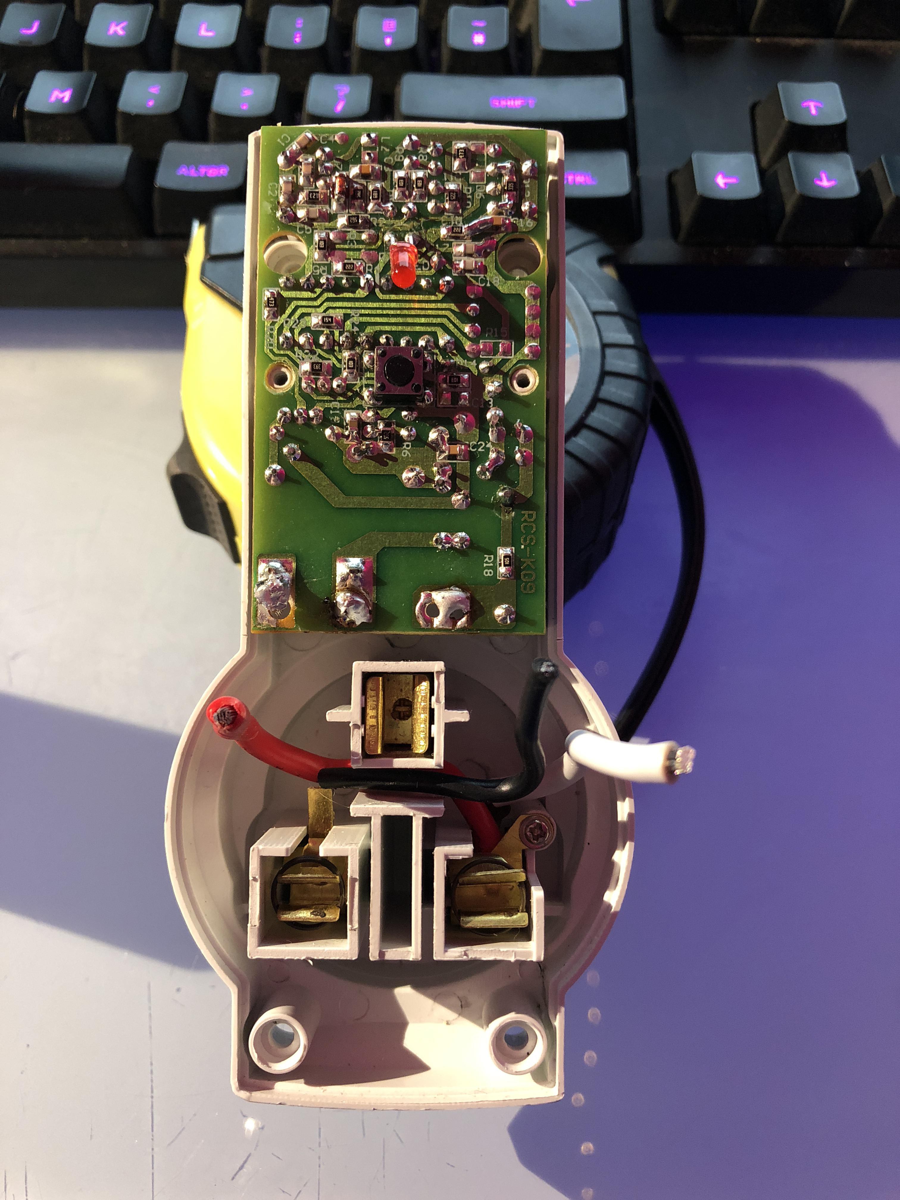
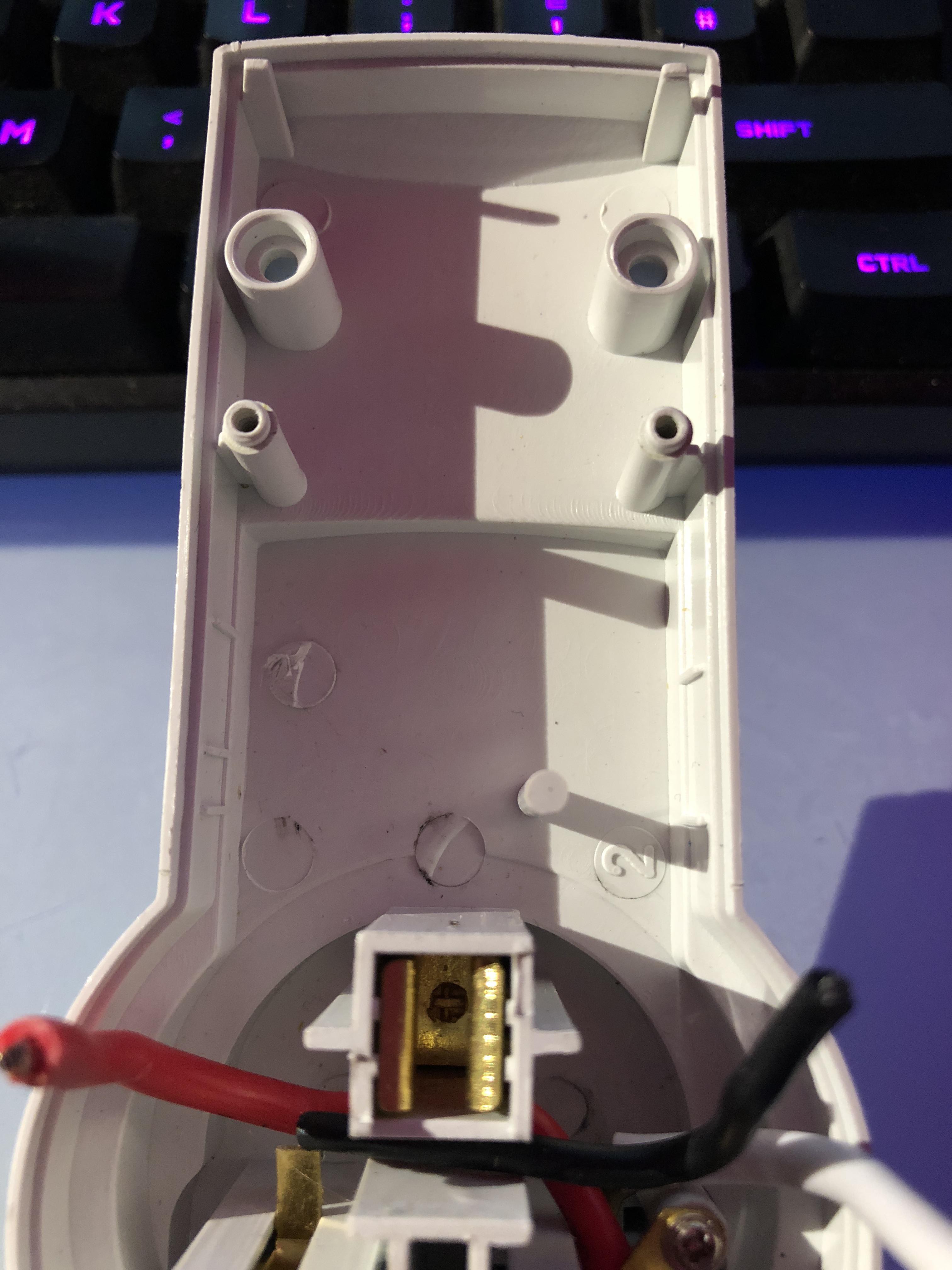
Here's what we have to work with:
---------- more ----------![]()
![]()
There's a bit of depth to work with underneath the board - just under 17mm at the bottom end, tapering off to around 13mm. The board itself is 37x65mm. There are two standoffs for securing the board in the middle, and two holes at the top for the standoffs for securing the other half of the enclosure. There's also one more support standoff underneath at the bottom of the board near the AC terminals to support the board. These restrictions will make placing some of the taller components quite tricky!
![]()
In the next update I'll start with the part selection.
-
Intro
11/29/2017 at 19:50 • 0 commentsI've been using 433mhz RF controlled plug sockets for home automation for around 5 years, and it has worked reasonably well. I started out sniffing the codes sent by the original remote control with an Arduino and a 433mhz receiver, before making an Arduino-based transmitter that received input over a serial connection from a server on my home network to control and automate various appliances in my home. As first this was just simple cron jobs to turn lights on at sunset, and a hacked together web interface to control sockets via my phone.
As times have moved on, I've embraced Apple's HomeKit ecosystem and the amazing community project Homebridge, which has a plethora of plugins available for controlling various connected devices. I was able to carry on using my 433mhz transmitter and shell scripts with the cmdswitch2 plugin.
This all works quite reliably 99% of the time, but there are a few downsides:
- Communication with the switches is one-way: they don't respond to an 'on' or 'off' signal, so we have no way of knowing whether the switch received the transmitted command and was able to perform the requested action. Interference can occasionally block sockets from receiving a command.
- Because of the lack of two-way communication, we cannot periodically pole the switch for its status. If the switch is turned on manually via its physical button, HomeKit will still think it's turned on - and won't attempt to turn it off (e.g. in a scene automatically triggered by leaving the house)
- The range on the sockets is surprisingly long, and communication is completely unencrypted - it would be trivial for someone within a hundred metres of my house to turn all my lights on at 3am!
- There is no EEPROM on the switches, so after losing power they go into learning mode and will bind to the first identifier broadcast.
Introducing a microcontroller with on-board WiFi will solve both of these problems, and also open some other interesting doors for future revisions of the project such as power consumption monitoring and reporting.