The first Alpha design is done. I need to review it before publishing.
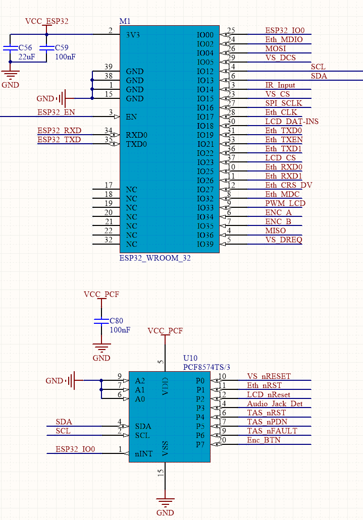
The limited amount of IO on ESP32 leads to use of an external I2C expander for slow control signals.
The pinout looks like this :

The ethernet PHY is clocked by ESP32, which prevent use of an external oscillator and associated circuit for not messing boot with IO0 level at start.
The rotary encoder is external to the board for an easier mechanical integration. Rotary signal are directly connected to ESP32, but the push button is on I2C expander.
IO0 is used as an interrupt input shared by I2C components.
USB update is through a CH340 with automatic reboot circuit.
Discussions
Become a Hackaday.io Member
Create an account to leave a comment. Already have an account? Log In.