Ted Yapo
-
Fizzle
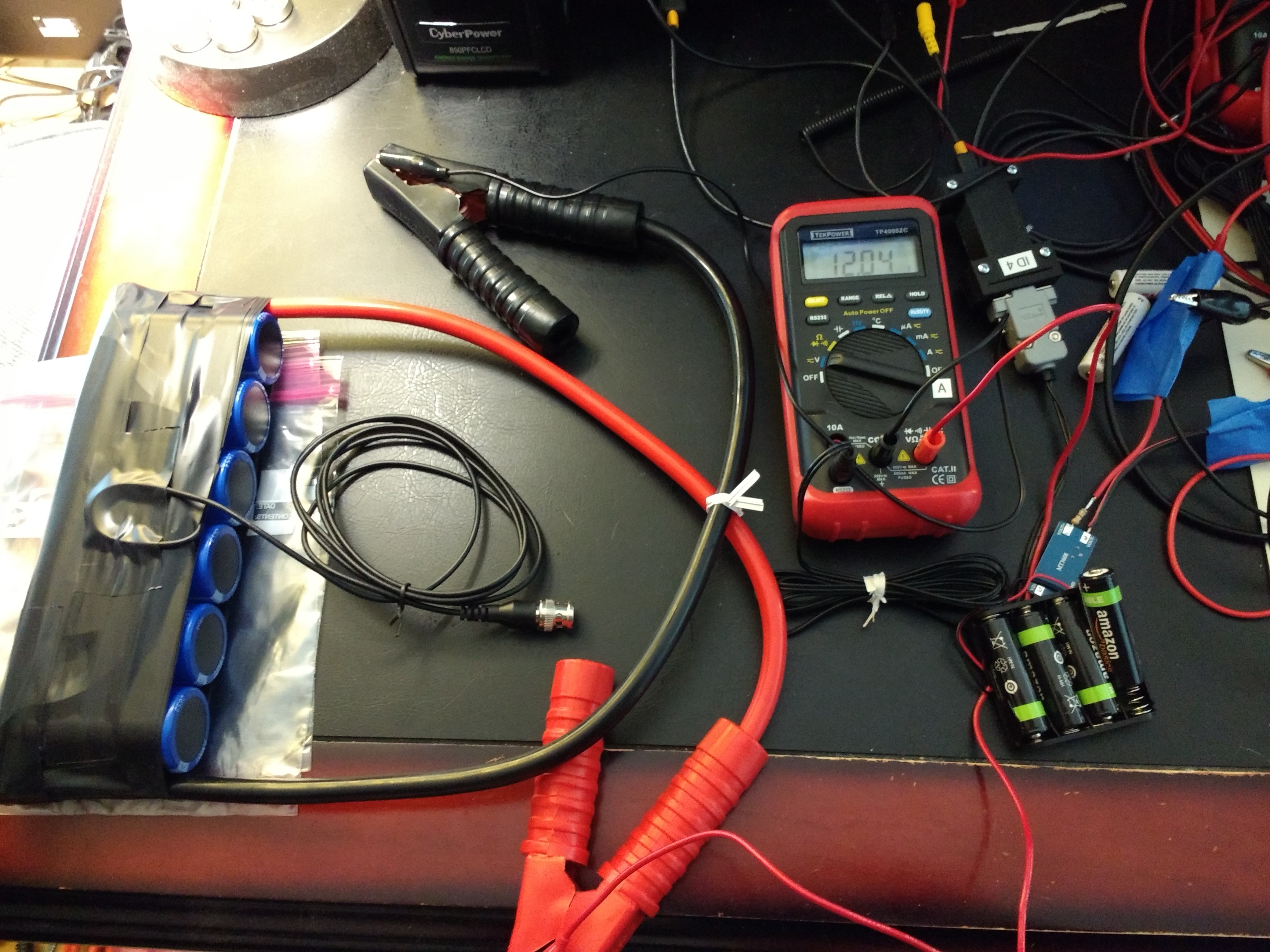
01/08/2018 at 18:54 • 4 commentsI'm going to admit defeat. My last hope to get the car started was charging a NiMH battery of 4 AA cells (previously shorted) with a LiSOCl2 cell of 1.5Ah capacity.
![]()
The NiMH cells read 1.33V after charging, which doesn't mean much. Figuring that not much charge had found its way into the cells, I decided to start with the capacitor at 11V. If I could boost this to around 14, start the engine, then show that the capacitor voltage was still above 11V, I'd consider it successful.
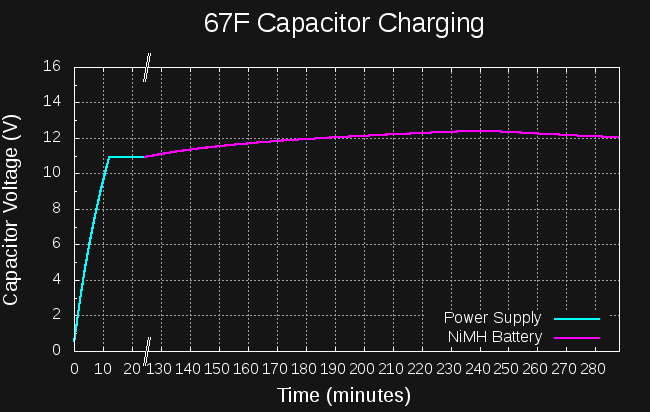
Here's the log of the capacitor voltage:
![]()
The initial almost-linear part was charging with my lab power supply at 11V, current-limited to 1A. The voltage climbed to 11V and stayed there (it's not quite linear probably due to resistance in the wires). After about an hour, I disconnected the lab supply, and put the caps on the boost converter driven by the NiMH cells (having been charged from the "coin cell"). I saw that it was working OK, and left to do some other things.
When I returned, I found that the capacitor voltage had peaked at 12.4V, then started dropping again. The NiMH cells were depleted. This means that 1097J had been deposited in the capacitor by the NiMH cells. Previous measurements had shown that 1500J are required to crank the engine.
So, it's not going to happen from one cell.
I have some more NiCd cells that were charged from LiSOCl2 cells and CR2477s, so I'll see if I can get the cap charged using the energy from multiple cells...
-
Now, *that's* a capacitor!
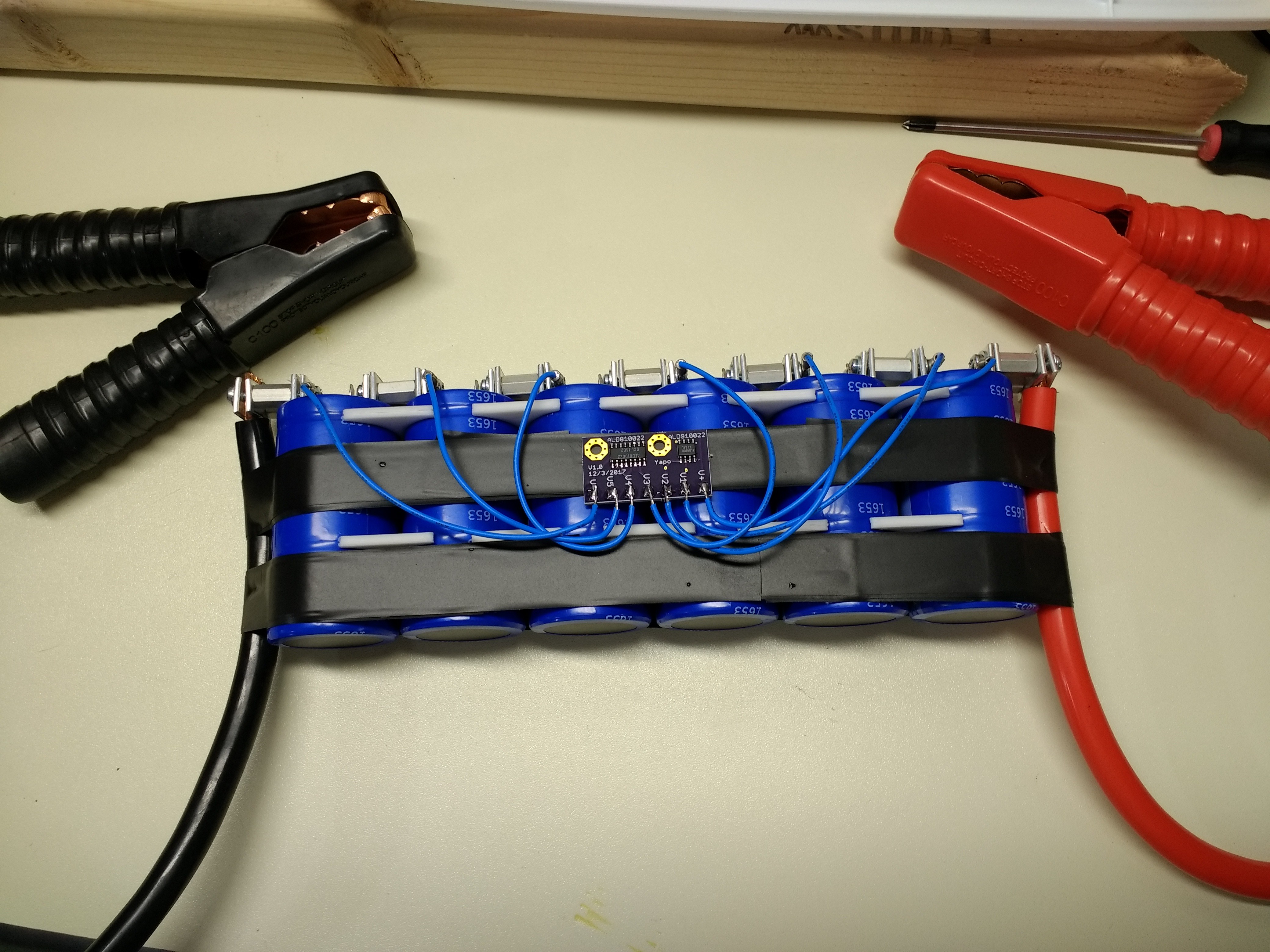
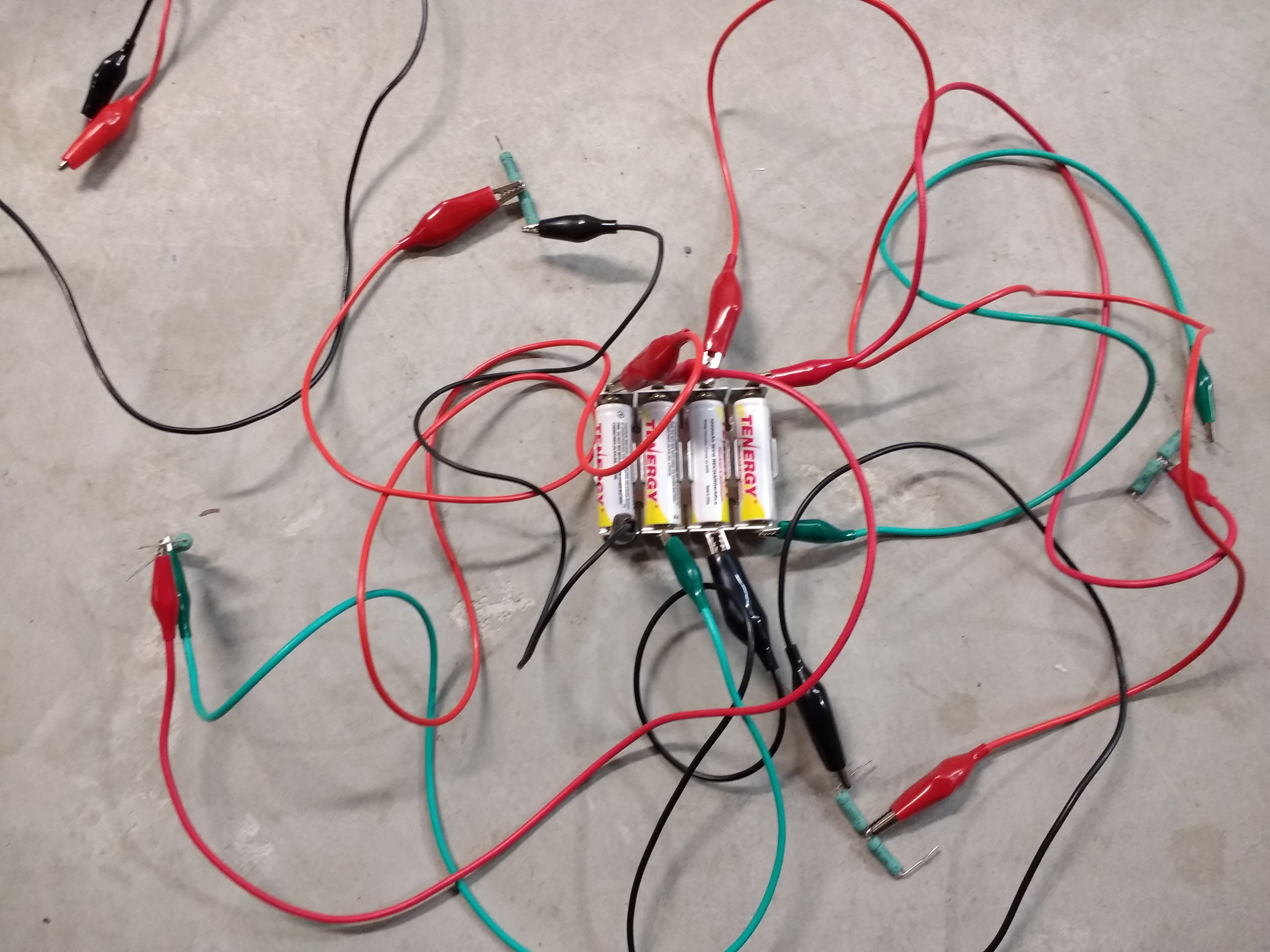
01/07/2018 at 21:47 • 0 commentsGood news, everyone! I assembled the 67F/16.2V capacitor, complete with cables and charge balance board. Let me show you the various lengths of wire I used:
![]()
I 3D-printed some spacers to keep the caps in line, bolted the terminals together with hex standoffs, wired the charge balance board to each node, clamped on the leads, then taped it all together. Afterwards, I insulated the whole assembly in a few layers of tape to avoid nasty shorts.
Now, I have to charge it. -
How to charge a capacitor efficiently
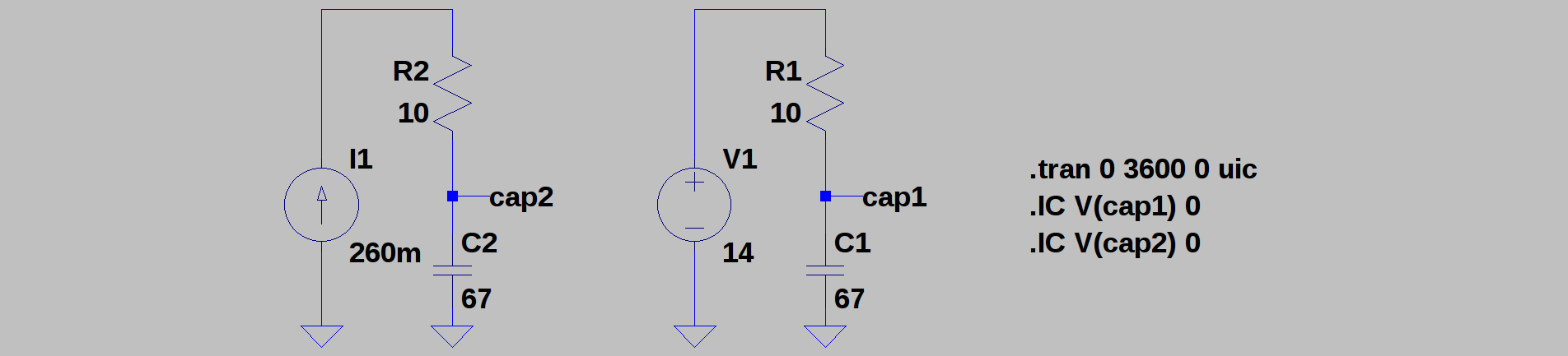
01/01/2018 at 22:44 • 0 commentsTI has an interesting application note about charging supercapacitors for energy buffering from LiSOCl2 cells. In their design, they use a microcontroller to slowly ramp up the output voltage of a DC-DC converter charging the capacitor to minimize losses. This is similar to charging with a current source instead of a voltage source. The difference is huge. Here's a simulation:
![]()
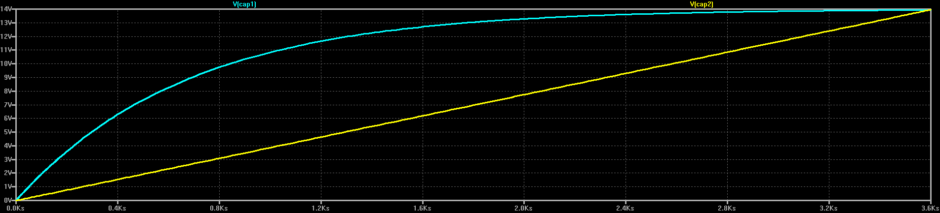
C1 and C2 are two identical 67F capacitors, charged through two identical 10-ohm resistors. On the right, the capacitor is charged from a fixed 14V source (for example, a voltage-feedback DC-DC converter). On the left, C2 is charged from a current source (more on how to do this later). As you'd expect, the voltage on C2 exponentially approaches 14V, while C2 shows a linear ramp (I've chosen the values so the two capacitors reach 14V at about the same time):
![]()
What you may not expect is that there's a huge difference in efficiency between the two. Charging C1 from the voltage source wastes half the energy in R1: in the simulation, 6.5 kJ end up in C1, and 6.56 kJ get dissipated in R1 (theoretically, they should be equal). This is 50% efficiency. It turns out that no matter what value you choose for R1, 50% of the energy is always wasted in the resistor.
On the other hand, C2 has 6.54kJ at the end of the simulation, while R2 has dissipated only 2.43kJ, for an efficiency of 73%. If we choose a 1-ohm resistor for R2 instead, only 243J end up wasted in R2: the efficiency is now 96%. You can decrease R2 as much as you like to further increase the efficiency.
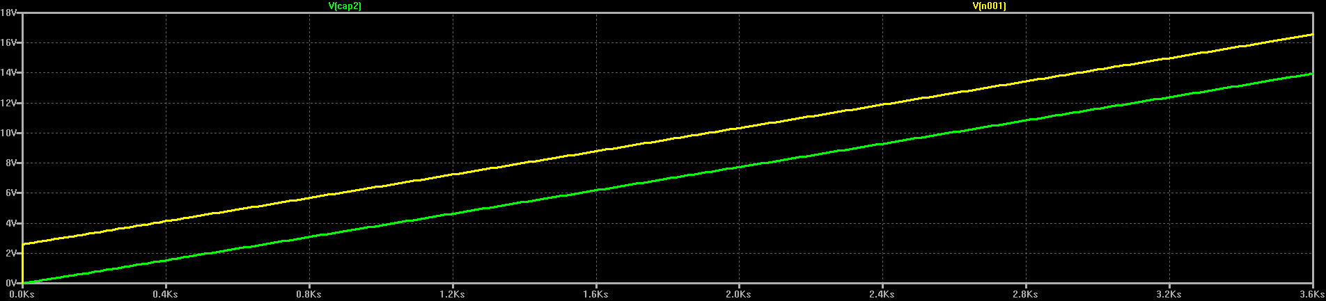
So, we should charge capacitors from current sources. In the TI app note, they emulate a current source by slowly ramping the voltage output of a DC-DC converter. If we look at the voltage at the output of the current source in the above simulation, we see a similar thing:
![]()
Here, the current source and R2 always keep the "charging voltage" a fixed amount above the capacitor voltage. Decreasing R2 decreases this voltage, and hence the power that gets wasted in the resistor.
Modifying common DC-DC converters for current output
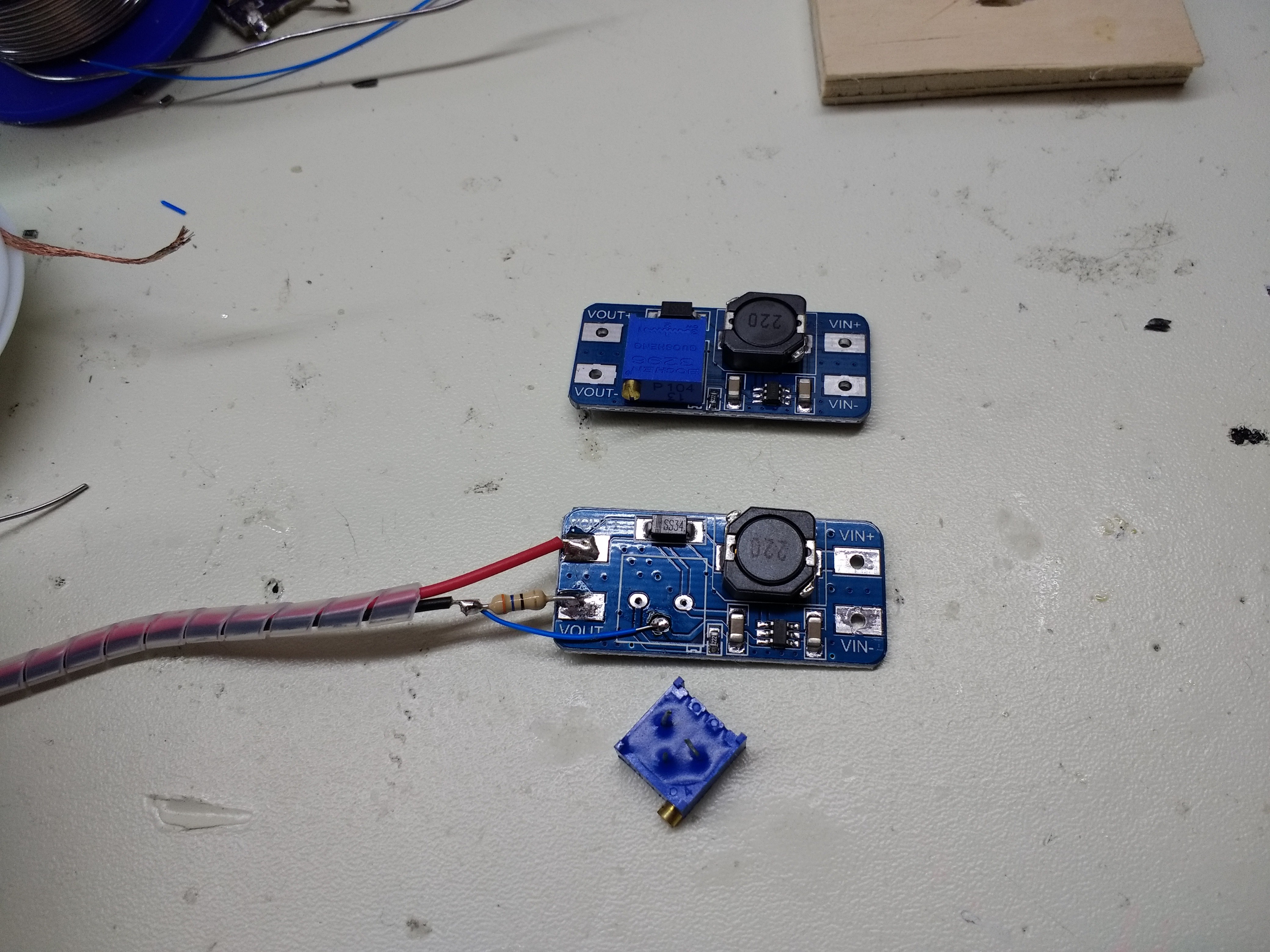
I happened to have a few MT3608 boost converter modules around. These converters accept inputs as low as 2V, can handle switching currents of up to 4A, and can output up to 28V. The modules have a 25-turn pot for adjusting the output voltage. A quick look at the MT3608 datasheet shows that this potentiometer controls the feedback from the output. The feedback is compared to 0.6V to regulate the output voltage.
I modified one of the boards by removing the output adjustment potentiometer and including a current sense resistor in the negative output line. The feedback voltage is taken from the top of the sense resistor.
![]()
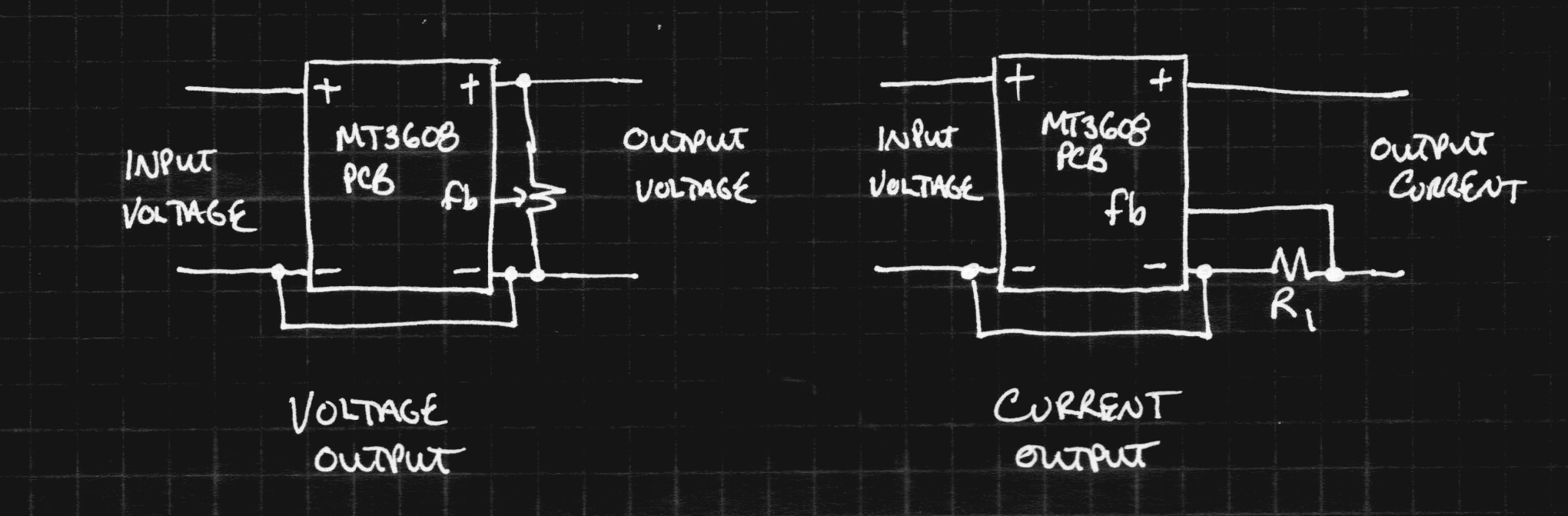
The before and after block diagrams are shown here. The rest of the circuit on the PCB isn't particularly relevant:
![]()
With the modified converter, the MT3608 tries to keep the voltage across R1 at 0.6V, no matter what the output voltage is. Now, the output is a current source, perfect for charging capacitors. By choosing R1, you control the output current according to:
It turns out that this is also a good way to control/limit the input current to the converter. I think I'm going to try charging NiCd's from another coin cell with one of these converters. It's likely to be more efficient than the homebrew converter I came up with.
-
NiCd cells charged
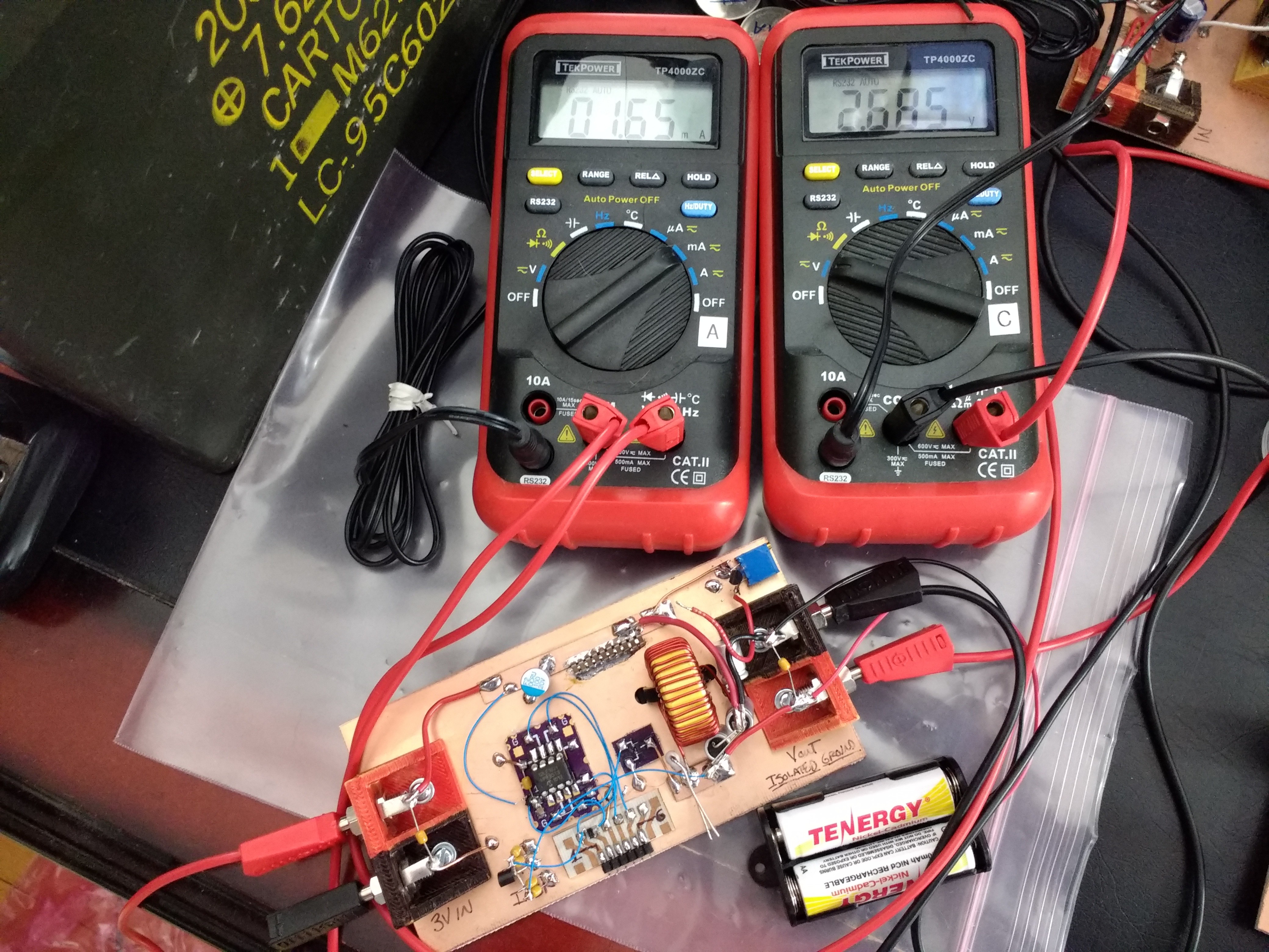
12/31/2017 at 16:04 • 0 commentsSo, my first experiment with charging NiCd cells is almost done. They have been charging from a CR2477 through the converter for more than a week now. The initial cell current of 2.5 mA has now dropped to 1.65, while the voltage is at 2.0, which would typically be considered dead.
![]()
The NiCd battery voltage is 2.685V at this point. This doesn't mean all that much, since you can't accurately infer the state-of-charge of the NiCd's from their voltage. I roughly guess that I was able to extract 70% of the energy from the coin cell (earlier modeling predicts 83%). Assuming a 60% converter efficiency (testing showed 65%), and 100% NiCd charging efficiency, I might have dropped 4000J into the NiCd's. It's taken a week to charge, so self-discharge has taken a toll, and maybe I managed to cram 3800J in there.
If I go with my top-off-the-capacitor plan, I'll need to transfer 1742 J to the capacitor to bring it from 12 to 14V. This allows me an efficiency of 45% for the second converter. It seems like it might be possible.
So, today, I have to finish building my capacitor bank and figure out some kind of boost converter to top off the capacitor with the NiCds. I have to hurry a little because I'm going to start losing energy to self-discharge in the NiCd's. For the moment, I suspect even the feeble current from the not-quite-dead-yet CR2477 is holding self-discharge at bay, but that won't last long.
Besides this one shot, I still have a week to try charging other NiCd's, so I have to get them going today, too.
-
Killing NiCd Cells
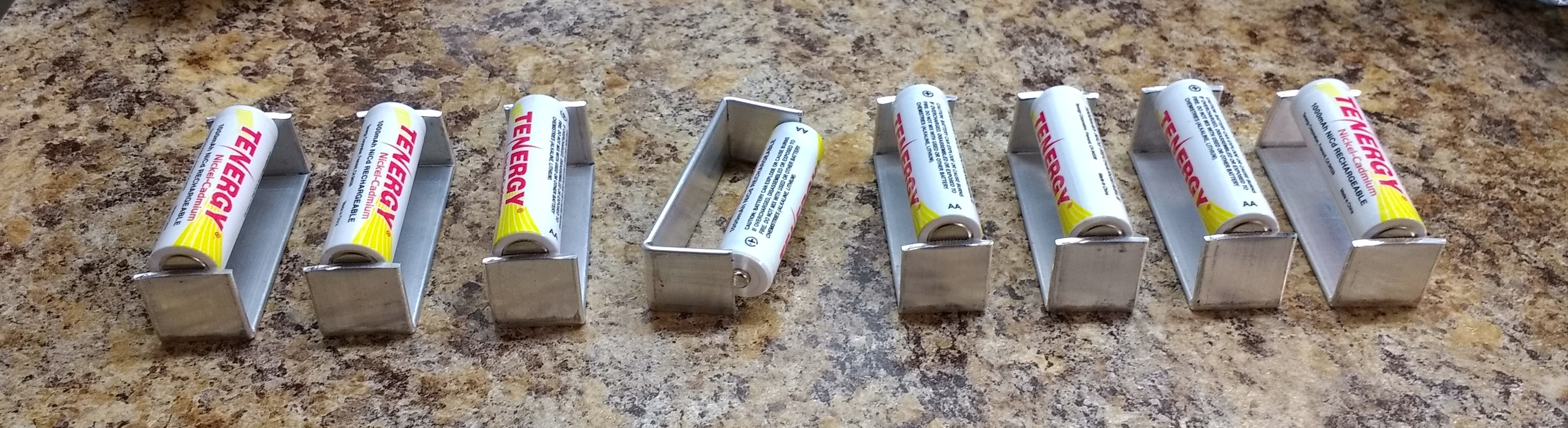
12/20/2017 at 18:16 • 0 commentsDon't worry: they'll come back as zombies later.
![]()
I made some shorting bars for AA NiCd cells from 1.5 x 20mm aluminum stock. The slight curvature of the stock created by my shears makes a nice contact for the negative battery terminal. They've been shorted like this since yesterday. This ensures the cells are at a "zero" state of charge. To prepare them for shorting, I first discharged them fully with 3.6 ohm and subsequently 1.8 ohm power resistors:
![]()
The lousy clip leads probably double the resistance, but the cells did eventually discharge.
How dead are they?
I intend to use the NiCd cells as an intermediate storage for the energy drained from a coin cell, since they self-discharge much more slowly than supercapacitors (1% per day vs 20% in the first day). The energy will then be transferred (quickly) from the NiCd's to the capacitors, since the capacitors can discharge with enough power to start the car.
Even though the NiCd's have been shorted for a long time, it's natural to wonder if there is any charge left in them. I can hear people crying foul already. But, it's a legitimate question: what's left in a NiCd after it has been stored shorted?
I took two cells out of their shorting bars and tested them. I connected the first to a high-impedance DMM to test the open-circuit voltage. Over the course of a few hours, the voltage slowly rose from 0 to 1.047V. This probably won't convince anyone that the cell is empty.
I connected the second cell directly to a DMM on the 2mA setting, then measured the voltage across the cell. The current crept up to 626uA, while the voltage rose to 65mV. This represents a power of 41 uW, which is ridiculously tiny.
To put this number in perspective, it would take 5 years to charge my 67F capacitor to 14V using a charging power of 41uW, assuming 100% efficiency and zero capacitor self-discharge. In contrast, I expect to charge the capacitor from the NiCd's in an hour or two.
My suspicion is that any minuscule residual charge that these measurements represent would eventually drain away during extended shorting. The open-circuit voltage recovery after shorting reminds me of dielectric absorption in capacitors: short a capacitor for a while, and the voltage will recover somewhat afterwards.
In any case, I'm not worried that there is any significant energy left in these cells. As an experimental control, however, I'll leave a set of identically shorted cells un-shorted while charging the others. Once the active cells have charged, I'll check how much the control set has recovered. I'd bet there won't be anything significant.
-
More Coin Cell Discharge Data
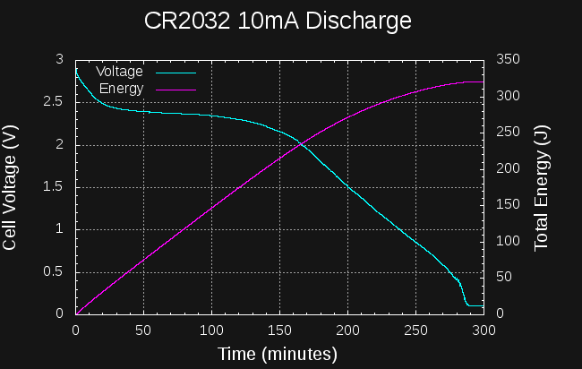
12/18/2017 at 03:32 • 0 commentsI tested a CR2032 cell at continuous 10mA discharge. The results aren't very good.
![]()
If we take 1.5V as the cutoff voltage, around 275J can be drained from the cell in a little over 3 hours. Draining down to the mV level gets you to 325J in just under 5 hours. This is roughly 12 and 14.5% of the cell's capacity, respectively.
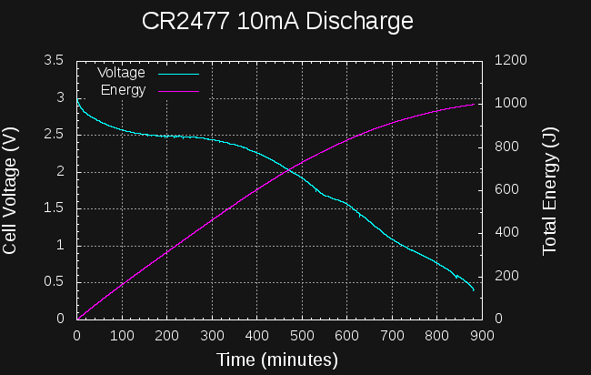
I tried the same experiment with a CR2477 cell:
![]()
This cell manages about 850J to the 1.5V level in 10 hours. I stopped the test about 15 hours in, when the energy reached 1000J; by this time the cell voltage is below 500mV. This isn't very good either, although it is roughly 3x the energy of the CR2032. The datasheets would have you believe the CR2477 can supply 4x or so at very low discharge rates (1000 vs 225 mAh), so I guess the relative performance of the cells I am seeing roughly makes sense.
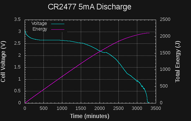
I also tried a longer test with a CR2477 at 5mA continuous drain.
![]()
In this case, the cell takes 43 hours to reach the 1.5V level. At this point, it has yielded around 1900J. If you can make used of the cell down to mV levels, you can get around 2100J at this current, but it takes 55 hours. Again, not very good at all.
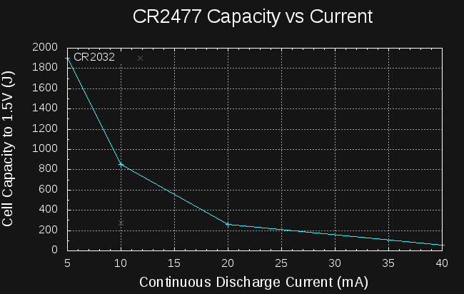
Looking at the four data points I have for CR2477 cells, we can see what effect the drain current has on the yield (I also add the single data point for CR2032):
![]()
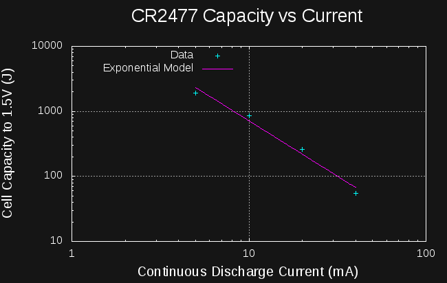
Yield is a very strong function of drain. I wondered how it would look on a log-log scale, so I plotted it, and it is roughly linear, hinting at an exponential relationship between capacity and current drain, similar to Peukert's Law for lead-acid batteries. Here are the data points along with a best fit line in the log-log space:
![]()
The exponential model is of the form:
where E is the energy yield of the cell in Joules, I is the discharge current in mA, and k and m constants. For the CR2477, a least-squares fit gives k = 35594, and m = -1.704.
Using this model, I would estimate that at 80mA, you should get 35594*80^-1.704 = 20J, while at 2.5 mA, you should get 35594*2.5^-1.704 = 7469 J.
Just like Peukert's Law, this model predicts you can get infinite energy by draining at lower and lower currents, so at some point it is no longer applicable. Just for fun, I re-arranged the equation to solve for the current you'd need to use to get 9000J (approximately full capacity) from a CR2477. The answer: 2.24 mA. This sounds like an interesting test, and if it wouldn't tie up my meters for five days, I'd start it now. Maybe after the contest :-)
-
DC-DC Converter Efficiency
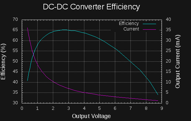
12/17/2017 at 15:47 • 0 commentsI must have figured this out while sleeping, because when I woke this morning, I knew I could use the cell discharge tester to measure the DC-DC converter efficiency. The discharge tester is an adjustable current load. By connecting this load to the output of the DC-DC converter and manually sweeping the current, I could record the converter efficiency as a function of output voltage.
![]()
The plot shows efficiency and output current vs output voltage for the homebrew converter tuned to draw 10.7mA from a 3V source. A 1.7Ah LiSOCl2 cell can supply this current without any decrease in capacity.
The efficiency peaks at 65% between about 2.5 and 3.5V output. This is a good match to charging a series battery of two AA NiCd cells (nominal 2.4V). To ensure good NiCd efficiency, I'll want to limit the cells to 70% charged, so I will probably use two sets of NiCd's in parallel, making a 2S2P pack of 2.4V / 2Ah capacity.
I ordered some 1000mAh NiCd cells, since I haven't had any around here in over a decade.
The efficiency of the converter is not very good compared to commercial offerings, but the input current is easily adjusted to a fixed value, an odd requirement for a power supply. I am not sure how easy this is to do with commercial switcher offerings. Does anybody know about this?
I will have to re-test this converter with a higher input current, because if the efficiency curve is the same, this converter is unsuitable for charging capacitors to 14V. At only 9V output, the efficiency has dropped to below 35%. The efficiency peak around 2.5V might make it OK for charging 2.7V capacitors in parallel (they would then be connected in series once charged). Even then, the steep drop-off of efficiency at low voltages isn't very good.
I still have to investigate commercial DC-DC converters for charging the supercapacitors.
The problem with the 10.7mA current is that it would take a week to get all the energy out of an LiSOCl2 cell at this rate. The cell is rated for 10mA continuous/50mA pulse, but I'm not sure how far I'm willing to push it. Going to 30mA would drain the cell in 57 hours, which seems more reasonable.
-
Capacitors? Why not NiCd's?
12/17/2017 at 04:24 • 5 commentsSo @EricH gave me an interesting idea. He asked if using an intermediate step with another set of capacitors could help with the energy transfer problem. If you could find large-valued capacitors with low self-discharge, you could take a long time to charge those with a coin cell, then charge the supercapacitor quickly from the intermediate caps. It sounds like it could work, but I don't think the right capacitor exists for this intermediate step.
What about using a rechargeable battery as the intermediate energy storage? This gets interesting. Everyone seems willing to allow an electrochemical capacitor as intermediate storage, so why not a rechargeable battery? (I'll refer to the coin cell as a "cell" and the rechargeable battery as a "battery" in the discussion below).
Let's forget about any technical problems for a minute and consider the contest judges and spectators. You have to convince them somehow that you're not running anything from energy pre-stored in the battery. Since state-of-charge is very difficult to measure accurately, I'm not even sure I wouldn't be cheating with most battery chemistries. The exception is NiCd, which can and should be stored with the terminals shorted and at a zero state of charge. It's how NASA stores their NiCd cells, as detailed in this technical report on NiCds. So, if I take a couple of AA NiCd's that have had their terminals shorted for a few days, then verify there is 0V across them, I think I can make a convincing argument that there's no energy hidden up my sleeve.
OK, so there's a way to verify that all the energy is coming from the coin cell. What are the properties of a NiCd battery?
- Nominal voltage 1.2V with a flat discharge curve.
- Can sustain very high rates of discharge (think of a cheap cordless drill).
- Self discharge rates quoted as 10% per month (wikipedia) or 1% per day (NASA TR).
- Tolerant of varied charging methods (C-rate and end-of-charge detection)
Overall, they sound like a good intermediate reservoir for energy storage. They have a much lower self-discharge rate than supercapacitors, so can be charged slowly from a coin cell without terrible losses (a DC-DC converter is still required). Then, once charged, they can be drained very quickly to charge the supercapacitor before supercap self-discharge becomes an issue.
What are the drawbacks? First, the energy will be going through two DC-DC converters, so losses get compounded there. Also, there's the charging efficiency of the NiCd's. Wikipedia mentions that at a C/10 charge rate, you have to apply around 1.5C of charge to fully charge a NiCd (equivalent to a 33% loss of energy). The NASA TR, however, shows that this ratio is a strong function of temperature (P. 13). With battery temperature near 0C, the ratio approaches 1, so much less energy is lost in charging.
So, can I take a 1.7Ah LiSOCl2 cell, charge some 1000mAh AA NiCd's, then use the NiCd's to charge a 67F capacitor to 14V? Here's how everything stacks up:
Storage Capacity (mAh) Energy (J) CR2477 1000 9000 TL-5935/P 1700 20000 2x NiCd AA 1000 8600 3x NiCd AA 1000 12960 4x NiCd AA 1000 17280 67F capacitor @14V - 6566 From the TL-5935/P datasheet, it looks like I can get the full 1.7Ah from the cell at 10mA, which is the maximum recommended continuous drain. I also estimate that the cell voltage will remain stable at around 3V for the entire discharge. Discharging at this rate will take 7.08 days. Assuming the 1% per day self-discharge rate for NiCd's, I might lose 600J during this week. Assuming a 33% loss due to NiCd charging inefficiency (which might be improved by cooling), and a 70% DC-DC converter efficiency, I end up with 8961 J in the NiCds, which almost fits in 2 AA's. I'll call it 8600 which just fits.
In order to charge the capacitor to 14V with the 8600J in the NiCd battery, I need a DC-DC converter with around 76% efficiency. Since the NiCd's can tolerate high current drain, I can use an efficient off-the-shelf converter, so that might not be too difficult to achieve.
It ain't pretty, and there's not much slack to play with, but it looks possible to start a car with a coin cell again.
EDIT: I found that charging efficiency for NiCd cells is nearly 100% until they reach 70% capacity. So, I can gain a lot of efficiency by using more NiCd cells and charging them to less than 70% capacity. Nice.
Also of interest is the PowerSonic NiCd Catalog. I need to pour over those graphs.
-
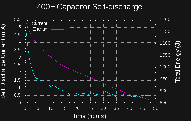
Capacitor Self-discharge
12/16/2017 at 18:13 • 0 commentsThe numbers are in on the self-discharge test. I charged a 400F capacitor to 2.33V with my bench supply, and let it soak at that voltage for about 2 hours. Then, I recorded the capacitor voltage over the next two days while the capacitor self-discharged.
![]()
To estimate the self discharge current, I fit a series of lines to the local voltage-vs-time curve using least-squares regression with a window of 2001 points wide (about 45 minutes of elapsed time). Some of the noise in the curve is due to the quantization of the voltage steps.
The datasheet specifies a 1mA maximum self-discharge after 72 hours. The capacitor meets the specification, with the leakage current dropping below 1mA after about 12 hours. After about 16 hours, the self-discharge current levels off at around 0.5 mA. The bad news is that the self-discharge current starts at around 5 mA, so 10% of the capacitor energy is lost in the first 5 hours, extending to 20% lost in 24 hours.
I don't know how this curve would look if the capacitor had been "soaked" for a longer time at 2.33V. It may be that if held at a specific voltage for an extended period of time, the initial self-discharge would decrease.
So far, I'm also not sure exactly how to apply this data to the charging problem. For instance, what does the leakage current look like during charging? Does it increase or decrease as the capacitor charges? In any case, the initial self-discharge current doesn't look good.
-
This is my hack...
12/16/2017 at 16:10 • 0 comments...and it's likely to spark some debate. Let me introduce the idea by way of an analogy. Let's say you're tired of the city and want to visit the country. Your friend agrees to lend you her car for the weekend so you can get away and clear your head. When you pick up the car from her, it has 3/4 of a tank of gas. The first thing you do is stop at the gas station to fill the tank and buy some snacks for the trip. The trip is great, and you return on Sunday evening completely refreshed. When you return the car, it has a little more than 3/4 of a tank of gas - say 7/16. Your friend notices you haven't used any of her gasoline, and says you can borrow the car again whenever you want.
After a few trips like this you decide it makes sense for you to buy your own car. Unfortunately, you are taken in by the slick salesman and end up with a car which has trouble starting. It turns out that the real issue is not the battery but the alternator - for some unknown reason, the alternator will keep the car running once it has started, but never re-charges the battery, not even a little. Luckily, your friend has a 67F capacitor she can lend you to start your car. When you pick up the capacitor it is charged to 12V, so contains 4824J of energy. Just like you did with the gasoline, you first "fill up" the capacitor to 14V (you happen to have a little device which does this) - now the capacitor contains 6566J. You connect the capacitor in place of your car battery, and start the car. Starting the car takes 1500J, so afterwards, the capacitor contains 5066J of energy, and is charged to 12.297V. Just as you did with her car, you return the capacitor to her with a little more energy than when you borrowed it. Again, she notices that you haven't used any of the energy in her capacitor, and offers to lend it to you whenever you need.
Unfortunately, the little device you have won't charge the capacitor from 0 to 14V, only from 12 to 14. So, if your friend lends you a fully discharged capacitor, you can't start your car. If, on the other hand, she lends you the same capacitor you began with, you always leave it with a little more energy than the last time you used it, and you can continue starting your car indefinitely using just the energy from your little device.
The Proposal
I don't know if I can extract 6566J from a coin cell fast enough to charge a supercapacitor, but I may be able to extract 1500J. In this case, I propose to begin with a capacitor charged to 12V, charge the capacitor to 14V, then start the car with it. By monitoring the voltage and current during starting with an oscilloscope, I can verify that the starting took less energy than was deposited in the capacitor by the coin cell. The numbers used here are just examples: the actual values will probably differ somewhat.
Ideally, I'd modify the car so that the alternator would not charge the capacitor once the engine is started (imagine a beefy ideal diode made with MOSFETs). The problem is that cars depend on the battery to filter the alternator voltage - with older cars, you could disconnect the battery once the car was running, but with modern computerized engines, this is asking for a whole lot of trouble. I am willing to believe that a 67F capacitor can stand in for the battery as a power supply filter, but don't think it is wise to have the capacitor isolated from the alternator once the engine is running. So, the next best thing is to analyze the voltage and current waveforms during starting to verify that none of the original charge of the capacitor was used in starting the engine.
Will the judges accept this argument? Will they disqualify my entry? What do you think?
Then again, maybe I can still find a way to get 6566J from a coin cell :-)