 Mike Rigsby
Let's see the results first:
I started with two discharged 350 farad capacitors.
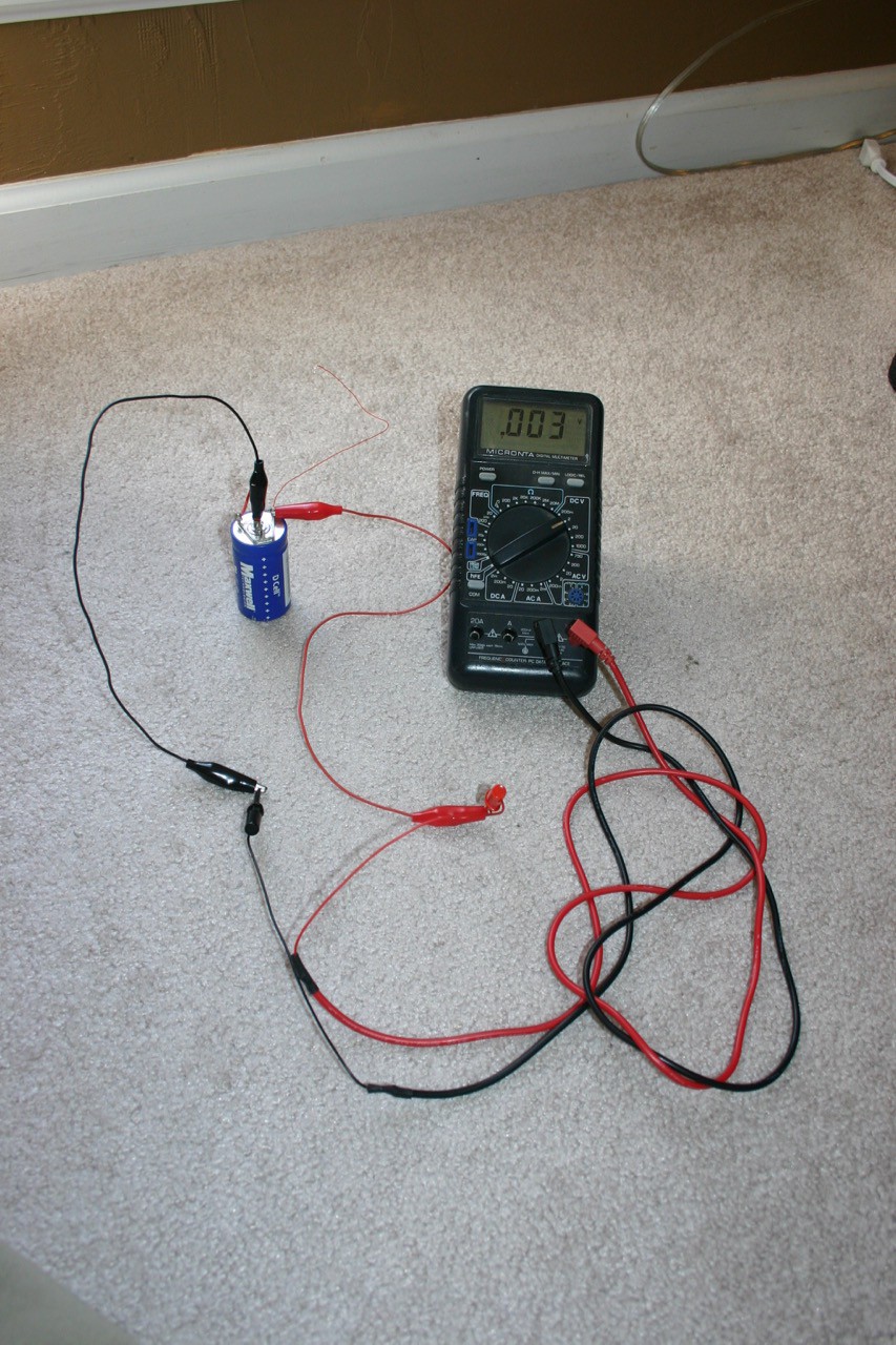
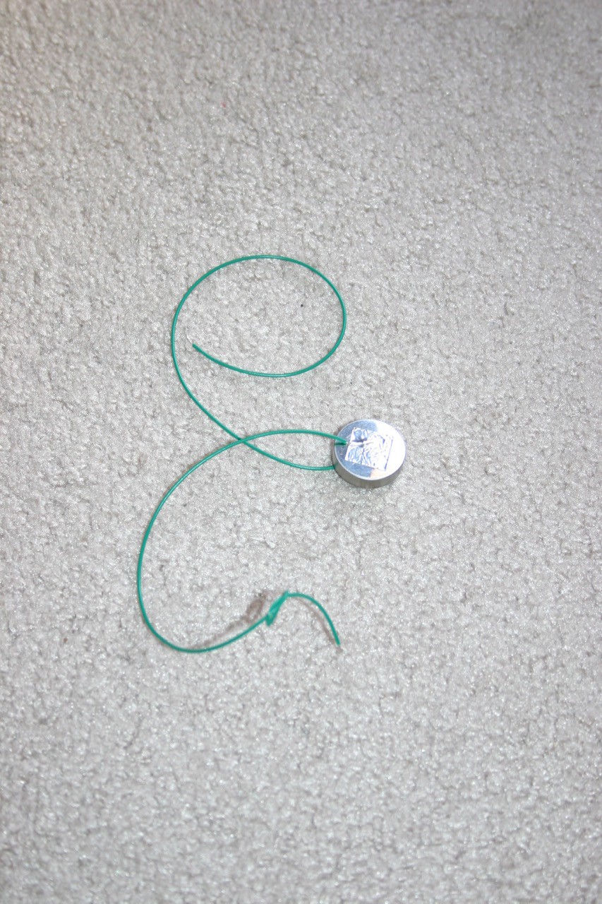
Next, I taped wires to a CR2477 coin cell and attached those directly to the capacitor. Nothing caught fire or exploded, so all was off to a good start.
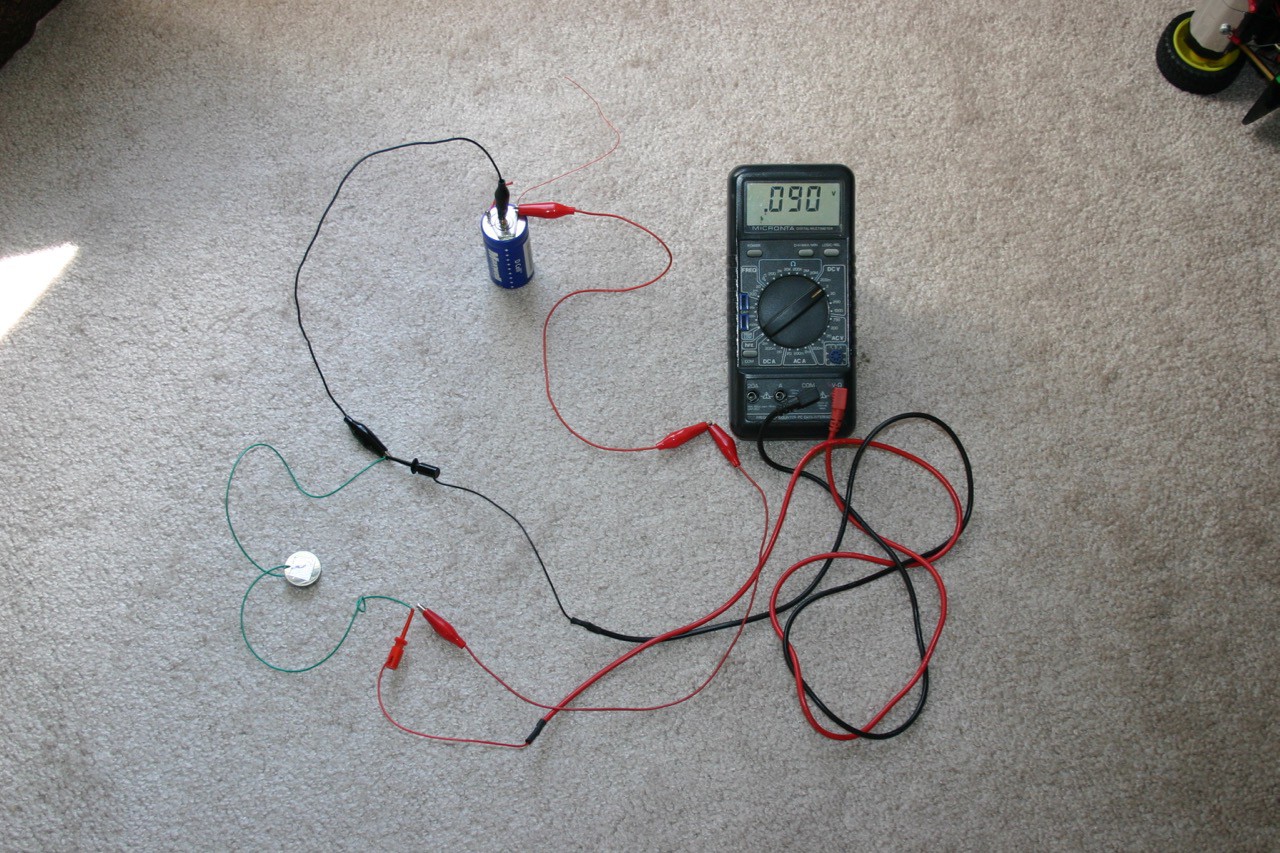
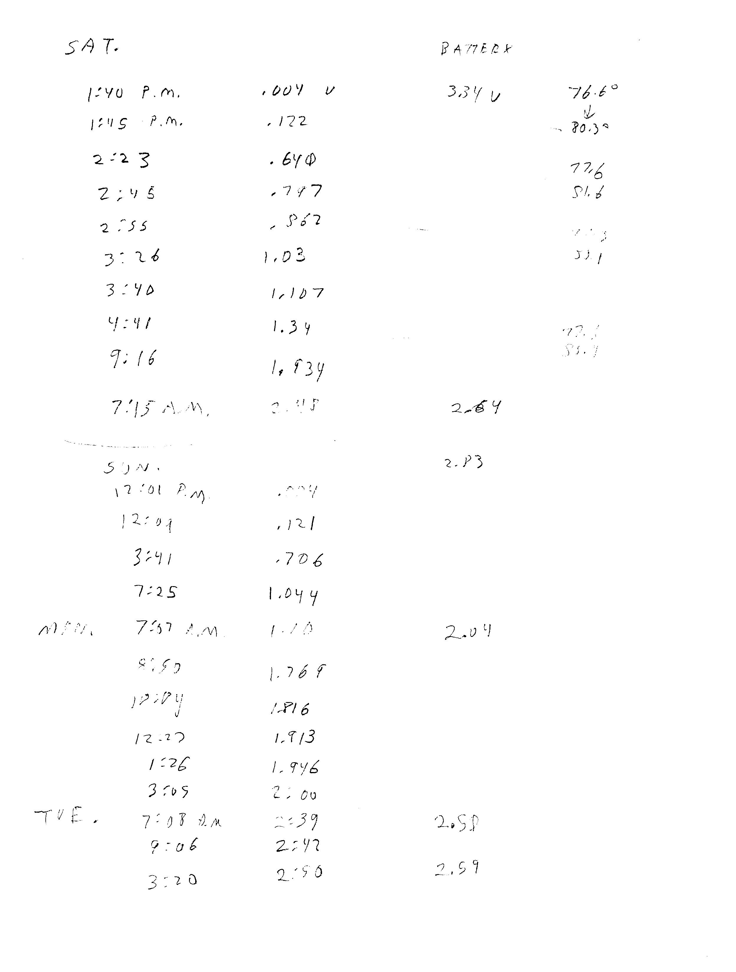
Beyond that, there was a slow collection of data. It took about 18 hours to charge the first capacitor to 2.5 volts. It required 51 hours to get the second one charged. Maybe a third could be done, but it would surely take a lot of time. Below is my highly organized data collection.
I used a DROK LTC1871 3.5V-30V Boost Converter (available on Amazon.com) to boost the capacitor voltage to the ten volts my train engine wanted.
My loaded train ran slightly more than once around the tree . . . there was still about 4 volts on the capacitor and over 2 volts on the coin cell, but my goal was to move a train (with nine attached cars), so I declare success and move on!
Yes; very good indeed. I suspect the major current draw will be: (a) the considerable inertia of the assembled consist (the loco and the wagons); and (b) the frictional losses in the locomotive; and (c) the friction between rails and wheel flanges, especially on the curves.
Impressive result.