Close
0%
0%

A Better Turret

Need a turret but the not impressed by the servo type. Perhaps a stepper motor version may be better.

Similar projects worth following
Using commonly available components, here is an attempt at a better turret based on stepper motors.

Parts

Bought the following parts:

  • 2x NEMA 17 stepper motor - 68 oz in (400 steps/rev)
  • 1x Pololu universal aluminum mounting hub for 5mm shaft M3 holes (2 Pack)
  • 2x NEMA 17 stepper motor mounting bracket
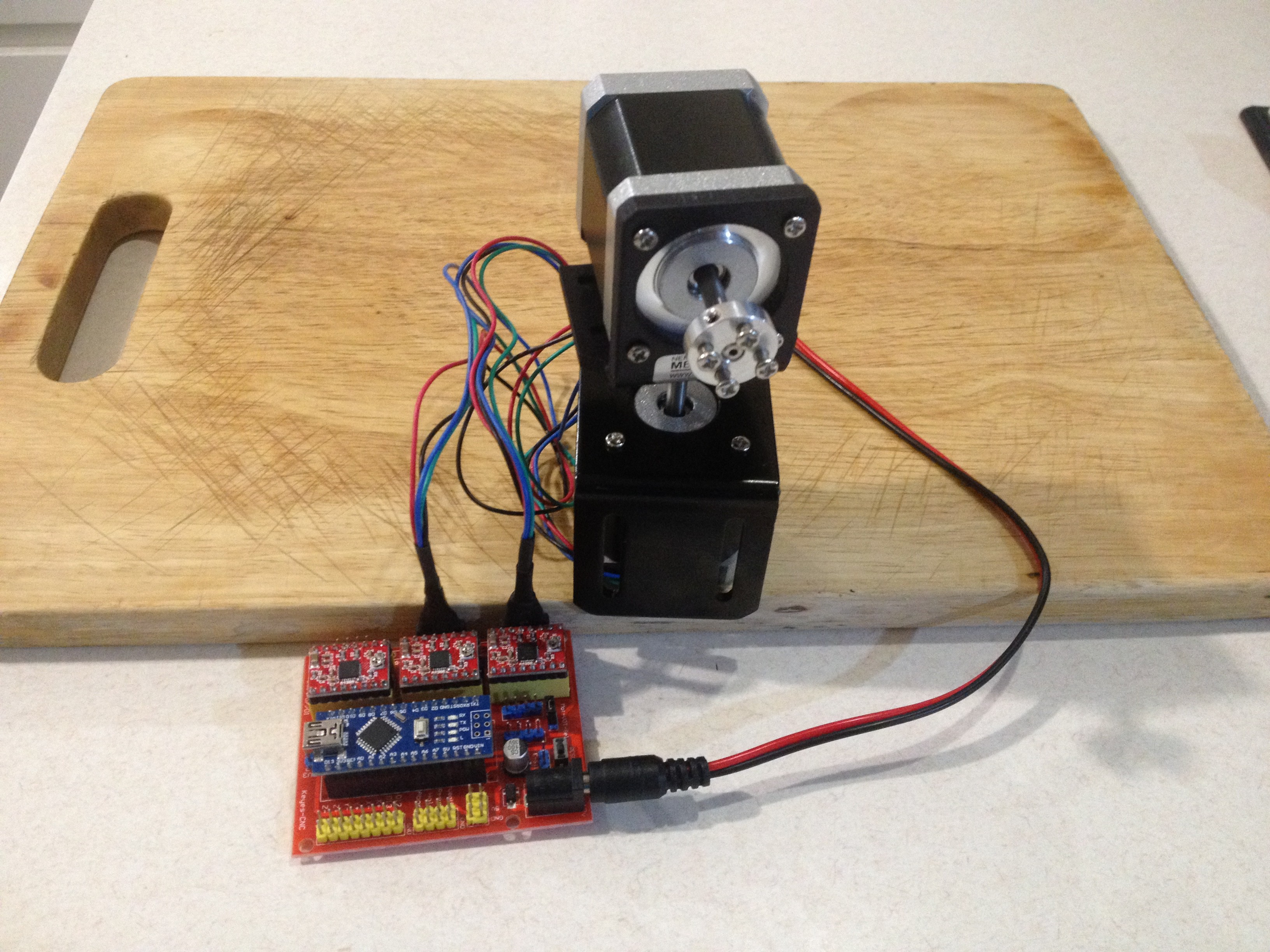
  • 1x Nano 3.0 CNC board (uses A4988 stepper motor drivers)
  • 1x 11.1v LiPo battery

Assembling the Turret

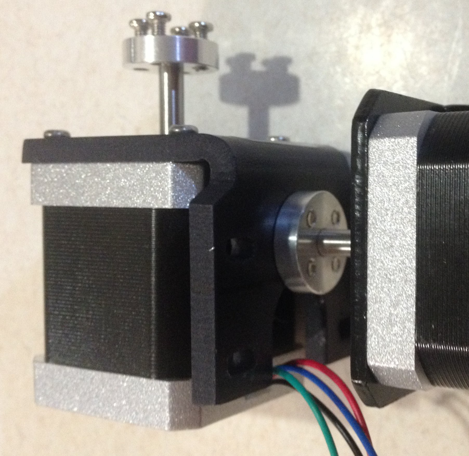
I drilled 4x 3 mm diameter holes in the base of one of the motor brackets to match the mounting hub:
Hook Up the CNC board

Here is what the CNC board looks like:

Almost no documentation in the Internet on this board!?

Mapping/tracing the Nano pins I get:

  • RX - Serial Receive (pin provided but not used)
  • TX - Serial Transmit (pin provided but not used)
  • D2 - X Direction
  • D3 - Y Direction
  • D4 - Z Direction
  • D5 - X Step
  • D6 - Y Step
  • D7 - Z Step
  • D8 - Enable
  • D9 - +/- X End Stops (pin provided but not used)
  • D10 - +/-Y End Stops (pin provided but not used)
  • D11 - +/-Z End Stops (pin provided but not used)
  • D12 - Free (pin provided)
  • D13 - Free (pin provided)
  • A0 - Abort (pin provided but not used)
  • A1 - Hold (pin provided but not used)
  • A2 - Resume (pin provided but not used)
  • A3 - Coolant Enable (pin provided but not used)
  • A4 - SDA (pin provided but not used)
  • A5 - SCL (pin provided but not used)
  • A6 - Free (pin provided)
  • A7 - Free (pin provided)

There are also:

  • +5v0 and ground pins
  • +3v3 and ground pins (uses an on board regulator)
  • Reset button (for Nano)
  • E-Stop pins (same as reset)
  • The power plug (Motor Power 8-12v):
    • Powers the Nano and via a shunt powers the A4988 stepper motor boards.
    • Otherwise the A4988 boards and the Nano are powered separately.
  • Under each A4988 stepper motor board are pins to shunt (S) the micro-stepping:
    • MS1 MS2 MS3 (up view)
    •      -        -       -  Full Step
    •      S       -       -  Half Step
    •      -       S       -    1/4 Step
    •      S      S       -   1 /8 Step
    •      S      S      S  1/16 Step   

    Here is the turret waiting for the battery pack (ordered), code and perhaps some cable sleeves:

Next

Get a laser pointer and write some code to control it (see logs).

AlanX

TurretScanISR.ino

x-arduino - 6.42 kB - 12/16/2017 at 04:03

Download

TurretScan.ino

x-arduino - 6.13 kB - 12/14/2017 at 07:00

Download

A4988.pdf

Adobe Portable Document Format - 1.04 MB - 12/12/2017 at 06:48

Preview

a4988Hookup.png

Portable Network Graphics (PNG) - 74.25 kB - 12/12/2017 at 06:48

Preview

a4988.png

Portable Network Graphics (PNG) - 84.72 kB - 12/12/2017 at 06:48

Preview

View all 9 files

  • ISR Motion Control

    agp.cooper12/16/2017 at 03:57 0 comments

    ISR Motion Control

    Reworked the code to use an ISR (Interrupt Service Routine).

    The ISR is pretty heavy duty but with the code optimisation it runs in less than 25 us. So it will run with a 16 MHz input clock (i.e. 31372.55 Hz interrupt rate). Still I slowed input clock down to 2 MHz for a 3921.57 Hz interrupt rate. As there is no ramp code, it is likely the stepper motors will miss steps if you try to go too fast.

    Here is the updated code:

    /*
      Simple 3 Axis Motion Controller
      ===============================
      Written by Alan Cooper (agp.cooper@gmail.com)
      This work is licensed under the Creative Commons Attribution-NonCommercial 2.5 License.
      This means you are free to copy and share the code (but not to sell it).
    */
    
    // Motor controller (CNC board) pin mapping: 
    #define DirX     2
    #define DirY     3
    #define DirZ     4
    #define StepX    5
    #define StepY    6
    #define StepZ    7
    #define Enable   8  // Active low
    #define Laser   12  // Turn laser on or off
    
    // Set motion (rate) steps per second
    unsigned long rate=1000;
    
    // Motor Controller direction settings
    bool xReverse=false;
    bool yReverse=true;
    bool zReverse=false;
    
    /* Motion ISR */
    volatile long xNew=0;           // The target X co-ordinate
    volatile long yNew=0;           // The target Y co-ordinate
    volatile long zNew=0;           // The target Z co-ordinate
    volatile long xCurrent=0;       // The current X co-ordinate
    volatile long yCurrent=0;       // The current Y co-ordinate
    volatile long zCurrent=0;       // The current Z co-ordinate
    volatile long steps=-1;         // Number of steps remaining in motion
    volatile unsigned int magic=0;  // Magic number (used by ISR)
    volatile unsigned int phase=0;  // Accumulator (used by ISR)
    ISR(TIMER2_OVF_vect)
    {
      static long stepX,stepY,stepZ;
      static long dx,dy,dz,ax,ay,az,sx,sy,sz,mx,my,mz;
      
      if (phase<0x8000) {
        phase+=magic;
        if (phase>=0x8000) {
          if (steps>0) {
            // Advance steppers
            stepX=0;
            stepY=0;
            stepZ=0;
            if ((ax>=ay)&&(ax>=az)) {
              if (my>=0) {
                my-=ax;
                stepY=sy;
              }
              if (mz>=0) {
                mz-=ax;
                stepZ=sz;
              }
              my+=ay;
              mz+=az;
              stepX=sx;
            } else if ((ay>=ax)&&(ay>=az)) {
              if (mx>=0) {
                mx-=ay;
                stepX=sx;
              }
              if (mz>=0) {
                mz-=ay;
                stepZ=sz;
              }
              mx+=ax;
              mz+=az;
              stepY=sy;
            } else {
              if (mx>=0) {
                mx-=az;
                stepX=sx;
              }
              if (my>=0) {
                my-=az;
                stepY=sy;
              }
              mx+=ax;
              my+=ay;
              stepZ=sz;
            }
            xCurrent+=stepX;
            yCurrent+=stepY;
            zCurrent+=stepZ;
            // Step HIGH
            if (stepX!=0) PORTD|=1<<StepX;
            if (stepY!=0) PORTD|=1<<StepY;
            if (stepZ!=0) PORTD|=1<<StepZ;
            steps--;
            // Disable ISR 
            if (steps==0) steps=-1;
          }
        }
        if (steps==0) {
          // Determine next movement parameters
          dx=xNew-xCurrent;
          dy=yNew-yCurrent;
          dz=zNew-zCurrent;
          // Check that there is something to do
          if ((dx!=0)||(dy!=0)||(dz!=0)) {
            ax=abs(dx);
            ay=abs(dy);
            az=abs(dz);
            sx=xNew<xCurrent?-1:xNew>xCurrent?1:0;
            sy=yNew<yCurrent?-1:yNew>yCurrent?1:0;
            sz=zNew<zCurrent?-1:zNew>zCurrent?1:0;
            if ((ax>=ay)&&(ax>=az)) {
              mx=0;
              my=ay-(ax>>1);
              mz=az-(ax>>1);
              steps=ax;
            } else if ((ay>=ax)&&(ay>=az)) {
              mx=ax-(ay>>1);
              my=0;
              mz=az-(ay>>1);
              steps=ay;
            } else {
              mx=ax-(az>>1);
              my=ay-(az>>1);
              mz=0;
              steps=az;
            }
            // Set the stepper directions
            if (xReverse) {
              // digitalWrite(DirX,(1-sx)>>1);
              if (sx==1) PORTD&=~(1<<DirX); else PORTD|=1<<DirX;
            } else {
              // digitalWrite(DirX,(sx+1)>>1);
              if (sx==-1) PORTD&=~(1<<DirX); else PORTD|=1<<DirX;
            } 
            if (yReverse) {
              // digitalWrite(DirY,(1-sy)>>1);
              if (sy==1) PORTD&=~(1<<DirY); else PORTD|=1<<DirY;
            } else {
              // digitalWrite(DirY,(sy+1)>>1);
              if (sy==-1) PORTD&=~(1<<DirY); else PORTD|=1<<DirY;
            } 
            if (zReverse) {
              // digitalWrite(DirZ,(1-sz)>>1);
              if (sz==1) PORTD&=~(1<<DirZ); else PORTD|=1<<DirZ;
            } else {
              // digitalWrite(DirZ,(sz+1)>>1);
              if (sz==-1) PORTD&=~(1<<DirZ); else PORTD|=1<<DirZ;
            } 
          }
        }
      } else {
        phase+=magic;
        // Reset step LOW
        PORTD&=~(1<<StepX);
        PORTD&=~(1<<StepY);
        PORTD&=~(1<<StepZ);
      }
    }
    
    #include <math.h> // For PI, radians(), sin() and cos()
    int iSin[360];
    int iCos[360];
    void setup()
    {
      // LED
      pinMode(LED_BUILTIN,OUTPUT);
    
      // Initialise Motor Controller
      pinMode(DirX,OUTPUT);
     pinMode(StepX,OUTPUT);
    ...
    Read more »

  • Test 2

    agp.cooper12/14/2017 at 01:55 3 comments

    Update to Code

    Spent the morning checking the code to determine why the X axis motor controller smoked. I don't know! The code seems to be doing what it should.

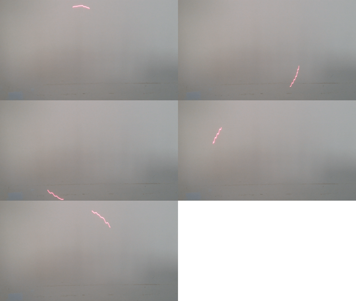
    The code now scans a circles. The circle is pretty rough:

    Set the driver to 1/8 micro-steps:

    It has taken me a while to determine that what I am seeing is overshoot:

    The overshoot is in the order of half a full step. Unfortunately there is not much I can do about it.

    Here is the current code:

    /*
      Simple 3 Axis Motion Controller
      ===============================
      Written by Alan Cooper (agp.cooper@gmail.com)
      This work is licensed under the Creative Commons Attribution-NonCommercial 2.5 License.
      This means you are free to copy and share the code (but not to sell it).
    */
    #include <math.h> // For PI, radians(), sin() and cos()
    
    // Motor controller (CNC board) pin mapping: 
    #define DirX     2
    #define DirY     3
    #define DirZ     4
    #define StepX    5
    #define StepY    6
    #define StepZ    7
    #define Enable   8  // Active low
    #define Laser   12  // Turn laser on or off
    
    // Motor Controller direction settings
    bool xReverse=false;
    bool yReverse=true;
    bool zReverse=false;
    
    // Movement control parameters
    long stepCountDown;              // Movement steps remaining
    unsigned long movementRate;      // Steps per second
    unsigned long movementInterval;  // Step period (uS)
    unsigned long movementRampIncr;  // Step period (uS)
    long xNew,yNew,zNew;             // New co-ordinates
    long xCurrent,yCurrent,zCurrent; // Current co-ordinates
    
    void motionControl(void)
    {  
      static unsigned long movementPreviousMicros=0;
      static unsigned long movementCurrentMicros=0;
      static unsigned long movementRamp;
      static long stepCountUp=0; 
      static long stepX,stepY,stepZ;
      static long dx,dy,dz,ax,ay,az,sx,sy,sz,mx,my,mz;
    
      // Process motion command at end of current movement
      if (stepCountDown==-1) {
        stepCountDown=0;
        stepCountUp=0;
    
        // Determine movement parameters
        dx=xNew-xCurrent;
        dy=yNew-yCurrent;
        dz=zNew-zCurrent;
        ax=abs(dx);
        ay=abs(dy);
        az=abs(dz);
        sx=xNew<xCurrent?-1:xNew>xCurrent?1:0;
        sy=yNew<yCurrent?-1:yNew>yCurrent?1:0;
        sz=zNew<zCurrent?-1:zNew>zCurrent?1:0;
        if ((ax>=ay)&&(ax>=az)) {
          mx=0;
          my=ay-(ax>>1);
          mz=az-(ax>>1);
          stepCountDown=ax;
        } else if ((ay>=ax)&&(ay>=az)) {
          mx=ax-(ay>>1);
          my=0;
          mz=az-(ay>>1);
          stepCountDown=ay;
        } else {
          mx=ax-(az>>1);
          my=ay-(az>>1);
          mz=0;
          stepCountDown=az;
        }
    
        // Set counters
        if (stepCountDown>0) {
          stepCountUp=1;
        } else {
          stepCountDown=-1;
          stepCountUp=-1;        
        }
    
        // Set the stepper directions
        if (xReverse) {
          digitalWrite(DirX,(1-sx)>>1);
        } else {
          digitalWrite(DirX,(sx+1)>>1);
        } 
        if (yReverse) {
          digitalWrite(DirY,(1-sy)>>1);
        } else {
          digitalWrite(DirY,(sy+1)>>1);
        }
        if (zReverse) {
          digitalWrite(DirZ,(1-sz)>>1);
        } else {
          digitalWrite(DirZ,(sz+1)>>1);
        }
      }
    
      // Advance Steppers 
      if (stepCountDown>0) {
        movementRamp=movementInterval;
        if ((stepCountUp==1)||(stepCountDown==1)) movementRamp+=movementRampIncr;
        
        movementCurrentMicros=micros();    
        if (movementCurrentMicros-movementPreviousMicros>movementRamp) {
          movementPreviousMicros=movementCurrentMicros;
                
          // Advance steppers
          stepX=0;
          stepY=0;
          stepZ=0;
          if ((ax>=ay)&&(ax>=az)) {
            if (my>=0) {
              my-=ax;
              stepY=sy;
            }
            if (mz>=0) {
              mz-=ax;
              stepZ=sz;
            }
            my+=ay;
            mz+=az;
            stepX=sx;
          } else if ((ay>=ax)&&(ay>=az)) {
            if (mx>=0) {
              mx-=ay;
              stepX=sx;
            }
            if (mz>=0) {
              mz-=ay;
              stepZ=sz;
            }
            mx+=ax;
            mz+=az;
            stepY=sy;
          } else {
            if (mx>=0) {
              mx-=az;
              stepX=sx;
            }
            if (my>=0) {
              my-=az;
              stepY=sy;
            }
            mx+=ax;
            my+=ay;
            stepZ=sz;
          }
          xCurrent+=stepX;
          yCurrent+=stepY;
          zCurrent+=stepZ;
    
          // Step pulse (high for at least 10 us)
          digitalWrite(StepX,abs(stepX));
          digitalWrite(StepY,abs(stepY));
          digitalWrite(StepZ,abs(stepZ));
          delayMicroseconds(10);
          digitalWrite(StepX,LOW);
          digitalWrite(StepY,LOW);
          digitalWrite(StepZ,LOW);
          stepCountDown--;
          stepCountUp++;
    
          // Flag end of movement 
          if (stepCountDown==0) {
            stepCountDown=-1;
            stepCountUp=-1;
          }
          
        }
        
      } else {
     movementPreviousMicros=micros();...
    Read more »

  • Test Run

    agp.cooper12/12/2017 at 06:32 0 comments

    Code

    I wrote some code (using Bresenham's algorithm) for the turret:

    /*
      Simple 3 Axis Motion Controller
      ===============================
      Written by Alan Cooper (agp.cooper@gmail.com)
      This work is licensed under the Creative Commons Attribution-NonCommercial 2.5 License.
      This means you are free to copy and share the code (but not to sell it).
    */
    
    // Motor controller (CNC board) pin mapping: 
    #define DirX     2
    #define DirY     3
    #define DirZ     4
    #define StepX    5
    #define StepY    6
    #define StepZ    7
    #define Enable   8  // Active low
    #define Laser   12  // Turn laser on or off
    
    // Motor Controller direction settings
    bool xReverse=false;
    bool yReverse=true;
    bool zReverse=false;
    
    // Movement control parameters
    bool pause=false;                // Pause movement
    long rampSteps;                  // start and stop ramp steps
    long stepCountDown;              // Movement steps remaining
    long stepCountUp;                // Movement steps completed
    long movementRate;               // Steps per second
    long movementInterval;           // Step period (uS)
    long ramp;                       // Ramp up/down period
    long xNew,yNew,zNew;             // New co-ordinates
    long xCurrent,yCurrent,zCurrent; // Current co-ordinates
    
    void motionControl(void)
    {  
      static unsigned long movementPreviousMicros=0;
      static unsigned long movementCurrentMicros=0;
      static long stepX,stepY,stepZ;
      static long dx,dy,dz,ax,ay,az,sx,sy,sz,mx,my,mz;
    
      // Process motion at end of current movement
      if (stepCountDown==-1) {
        stepCountDown=0;
        stepCountUp=0;
    
        // Determine movement parameters
        dx=xNew-xCurrent;
        dy=yNew-yCurrent;
        dz=zNew-zCurrent;
        ax=abs(dx);
        ay=abs(dy);
        az=abs(dz);
        sx=xNew<xCurrent?-1:xNew>xCurrent?1:0;
        sy=yNew<yCurrent?-1:yNew>yCurrent?1:0;
        sz=zNew<zCurrent?-1:zNew>zCurrent?1:0;
        if ((ax>=ay)&&(ax>=az)) {
          mx=0;
          my=ay-(ax>>1);
          mz=az-(ax>>1);
          stepCountDown=ax;
        } else if ((ay>=ax)&&(ay>=az)) {
          mx=ax-(ay>>1);
          my=0;
          mz=az-(ay>>1);
          stepCountDown=ay;
        } else {
          mx=ax-(az>>1);
          my=ay-(az>>1);
          mz=0;
          stepCountDown=az;
        }
    
        // Set counters
        if (stepCountDown>0) {
          stepCountUp=1;
        } else {
          stepCountDown=-1;
          stepCountUp=-1;        
        }
    
        // Set the stepper directions
        if (xReverse) {
          digitalWrite(DirX,(1-sx)>>1);
        } else {
          digitalWrite(DirX,(sx+1)>>1);
        } 
        if (yReverse) {
          digitalWrite(DirY,(1-sy)>>1);
        } else {
          digitalWrite(DirY,(sy+1)>>1);
        }
        if (zReverse) {
          digitalWrite(DirZ,(1-sz)>>1);
        } else {
          digitalWrite(DirZ,(sz+1)>>1);
        }
    
      }
    
      // Advance Steppers 
      if ((pause==false)&&(stepCountDown>0)) {
        movementCurrentMicros=micros();
        if (movementCurrentMicros-movementPreviousMicros>ramp) {
          movementPreviousMicros=movementCurrentMicros;
          
          // Start/stop ramp
          if (stepCountUp<=rampSteps) ramp-=movementInterval;
          if (stepCountDown<=rampSteps) ramp+=movementInterval;
          
          // Advance steppers
          stepX=0;
          stepY=0;
          stepZ=0;
          if ((ax>=ay)&&(ax>=az)) {
            if (my>=0) {
              my-=ax;
              stepY=sy;
            }
            if (mz>=0) {
              mz-=ax;
              stepZ=sz;
            }
            my+=ay;
            mz+=az;
            stepX=sx;
          } else if ((ay>=ax)&&(ay>=az)) {
            if (mx>=0) {
              mx-=ay;
              stepX=sx;
            }
            if (mz>=0) {
              mz-=ay;
              stepZ=sz;
            }
            mx+=ax;
            mz+=az;
            stepY=sy;
          } else {
            if (mx>=0) {
              mx-=az;
              stepX=sx;
            }
            if (my>=0) {
              my-=az;
              stepY=sy;
            }
            mx+=ax;
            my+=ay;
            stepZ=sz;
          }
          xCurrent+=stepX;
          yCurrent+=stepY;
          zCurrent+=stepZ;
    
          // Step pulse (high for at least 10 us)
          digitalWrite(StepX,abs(stepX));
          digitalWrite(StepY,abs(stepY));
          digitalWrite(StepZ,abs(stepZ));
          delayMicroseconds(10);
          digitalWrite(StepX,LOW);
          digitalWrite(StepY,LOW);
          digitalWrite(StepZ,LOW);
          stepCountDown--;
          stepCountUp++;
    
          // Flag end of movement 
          if (stepCountDown==0) {
            stepCountDown=-1;
            stepCountUp=-1;
          }
          
        }
        
      } else {
        movementPreviousMicros=micros(); // Reset movement rate clock to ensure near full cycle on start
      }
      
    }
    
    void setup()
    {
      // Initialise Motor Controller
      // Note: The motor controller is using 1/16 micro-stepping
      pinMode(DirX,OUTPUT);
      pinMode(StepX,OUTPUT);
      pinMode(DirY,OUTPUT);
      pinMode(StepY,OUTPUT);
      pinMode(DirZ,OUTPUT);
      pinMode(StepZ,OUTPUT);
      pinMode(Enable,OUTPUT);
      pinMode(Laser,OUTPUT);
      digitalWrite(DirX,LOW);
      digitalWrite(StepX,LOW);
     digitalWrite(DirY,LOW);
    ...
    Read more »

  • Inspirational

    agp.cooper12/07/2017 at 10:21 0 comments

    Inspirational

    I found this doing an Internet search of "Animatronics":

    Source: "See RoboBones and RoboHead" (http://www.animatronics.org)

    Back to Work

    Elected not to shunt the external Nano power supply to the motor power supply.

    The external power supply input has a schottky to protected against reverse power supply connections. This has the unintended consequence of preventing back EMF from returning to the battery (usually desirable). Instead any back EMF has to be absorbed by the driver boards or the Nano board.

    I had lots of problems with back EMF trying to use a common external battery in the past so this time around I will have two separate power supplies.

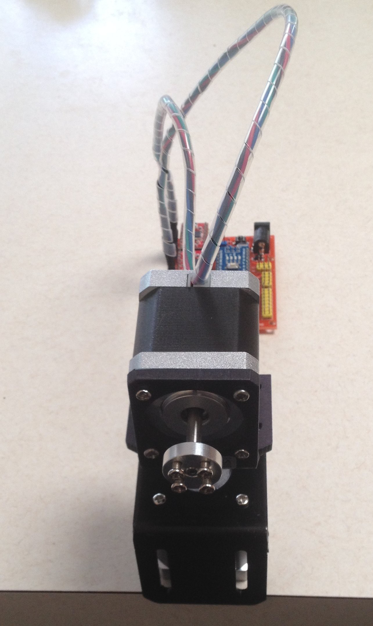
    Added some cable sleeves:

    Working on the Code

    A bit more complicated then I expected. Do I want to move at an arbitary  direction? I suppose I do, so I will gave to code a Bessenham's line drawing algorithm.

    Set up an Interrupt Service Routine (ISR) for the step pulse generator. I have limited the maximum pulse rate to 500 PPS, which is safe from a standing start for full step operation for nearly all common stepper motors. Should be able to bump this up for micro-stepping.


    Magic

View all 4 project logs

Enjoy this project?

Share

Discussions

agp.cooper wrote 11/05/2023 at 01:20 point

Hi TM,

My code was about moving the turret from A0,B0->A1,B1 (polar coordinates).

At the time I was considering a mechanical brake to prevent overshoot.

Belt drive seemed the next step for me.

You may be able to add PID without feedback to control the stepper motor overshoot.

Perhaps you can control pulse rate and/or current and/or micro stepping.

Depends of what you can control on the stepper motor driver chip.

You may need to design your own driver circuit or find one the allow this fine control.

The other option is to use a position sensor ($) and use closed feed back PID to control the 

stepper motor driver chip.

Other than belt drive I suspect none of the above will be out of the box, as you seem to be requesting.

Still have a look at PID, its not that hard and someone may have already done the work.

Regards Alan

  Are you sure? yes | no

TM Russell wrote 11/04/2023 at 21:40 point

Awhile back I came across this project: (https://jjrobots.com/remotely-controlled-laser-pointer/)
I really liked the look and idea but it turned out that the Devia board used for this project was no longer being made. I am looking to see if anyone has any ideas for an alternative to make this work? I was thinking using an ESP32 since it has BT to intergrade a PS3/Xbox controller. A few boards I have on hand are the MKS DLC32 cnc board or an ESP32 based Uno R3 board with a cnc shield. If anyone could help, I would be so grateful. I am not new to coding, but no expert by any means. If anyone has some input for this, PLEASE let me know. Thank you.

  Are you sure? yes | no

agp.cooper wrote 12/15/2017 at 02:44 point

Hi Florian,

The datasheet was 15' of arc which is 0.25 degrees. I used degrees to avoid unit change and possible confusion (fail!).

Yes pre-loading is an option as is mechanical damping of overshoot but both these add mechanical construction complexity to the project. Considering that the steppers pull a few Gs in normal operation, pre-loading need to be quite significant to be effective (i.e. not just at low speeds).

Backlash compensation in software simply allows for the gearbox movement in software. Not quite that simple as it changes with speed and loading.

To recap the current turret performance: precision is 0.11 degrees, overshoot about 0.23 degrees from the mean. If allowed to settle then accuracy is about 0.11 degrees. Uses off the shelf components. These measurements were at a crazy speed of 60 RPM! All for less than $100.

Open questions:

(1) Is better performance available using a precision planetary gear stepper?

(2) When will 0.36 degree steppers be available!

For this project I don't see any simple improvements that I can make that would greatly increase the performance.

---

By the way I like your laser cut planetary gear project. Neat. I assume you are press fitting the pinion gear. I had lots of problems in this area. Here is an idea (forget where I found it):  https://cdn.hackaday.io/files/12929553154336/LaserCutWheelCentre.jpg

Regards AlanX

  Are you sure? yes | no

Florian Festi wrote 12/15/2017 at 09:43 point

Sorry for the arc minute confusion. By pure chance the fist stepper I opened had a 25 arc minutes back lash.

Also I see pre-loading as a way to get rid of back lash not as a cure of the overshoot. The way to deal with the overshoot is gearing down to the point where is does not longer matter.

As I use plywood for my gears pressing them on is pretty easy as wood is a sponge like material and the laser cutter can deliver enough precision to get the pressure just right. But I use steppers with flattened axis. So transferring torque is not that much of an issue

Could you try one thing: Put the stepper with the laser on a small board at least about 20cm long with the axis pointing up. It probably does not even need to be fixed. Then lift the end of the board up with a string wound around the other stepper's axis. This should create a backlash free ~1:10 reduction (with very limited travel). I am curious if the approach is feasible.

  Are you sure? yes | no

agp.cooper wrote 12/15/2017 at 10:41 point

The use of nylon with steppers has been done before. I remember a CNC machine done that way. Not the one I was looking for but close enough:

https://www.youtube.com /watch?v=0UigQApV01o

(Kill the space in the link above!)

Main downside that I can see is low rigidity and without a position sensor, no real idea where the pointer is pointing. Why not use a timing belt and two pulleys for this? They are pretty rigid, known gearing, no slippage and parts are off the shelf.

Did you have a design in mind?   

AlanX

  Are you sure? yes | no

Florian Festi wrote 12/15/2017 at 11:44 point

The benefit of using a string is the much smaller diameter of the drive "pulley" when using the motor shaft. Getting to a 1:10 or even 1:20 reduction with timing belts will either require a lot of space or a two stage reduction (which may be just fine). 

I've build a styrofoam cutter using fishing line a few yeas back. But ofc it does not have that huge demands on precision.

I would also not drive the fishing line by the shaft but wind it up which solves the problem of slippage. As forces as pretty small something like a 40kg (100lb) braided fishing line should hold up with very little stretch.

Oh, my 1:10 estimate above is wrong. 20cm is the radius. So it is more like 3.5mm to 200mm: ~1:60

  Are you sure? yes | no

Ted Yapo wrote 12/14/2017 at 03:32 point

I like this idea.  I used a commercial stepper version about 10 years ago for a LIDAR scanner prototype.  It used to skip steps when it moved too fast, and so occasionally needed to be "homed" to get back in sync.

I wonder if you can achieve better performance using a smaller stepper motor mounted on a larger one - that way, the larger one doesn't have to move as much mass.  It seems like the bulk of the work done by the first stepper is moving the second one around.  It's the Popeye problem :-)

  Are you sure? yes | no

agp.cooper wrote 12/14/2017 at 04:34 point

There is a smaller/shorter 0.9 degree NEMA 17 stepper motor that I was looking at. But best to stay simple to begin. The code is from my "Not GRBL" project so I have spent some time looking at pulse train ramps in the past in order to go fast and not miss steps. But the ramp was slowing down the stepper motor more than it should. At the moment I think I have a coding error (https://cdn.hackaday.io/images/6669941513225333746.png).

AlanX

  Are you sure? yes | no

agp.cooper wrote 12/14/2017 at 05:30 point

Okay, I checked the code and it is fine. The problem is overshoot. So although I am not missing steps, micro-stepping is not as "firm" as full step (which I was previously using for my laser CNC board). So it is a good as it gets.

AlanX

  Are you sure? yes | no

Florian Festi wrote 12/14/2017 at 10:08 point

Running the steppers faster may smooth out the path - probably at the cost of absolute precision. When running slowly stepper do - as the name suggests - steps. So the shaft jumps forward and then stops again waiting for the next step. This creates a lot of noise and vibration. If the stepper turns fast enough the rotor never stops but continues moving. IN this mode the rotor is always lagging behind the magnetic field a bit (which is what creates the torque).

So one reason to gear down the steppers can be just the be able to move them quicker to reduce the noise.

But to be honest I don't fully understand all the relations between noise, speed and micro stepping.  

  Are you sure? yes | no

agp.cooper wrote 12/13/2017 at 14:05 point

Hi Florian,

According to the documentation of a commonly available geared stepper motor, the backlash is quoted as <=1 degree. This is why I did not use a geared stepper motors for his application. I could have used a geared stepper motor as I have four of them. Yes there are special geared stepper motor with better backlash but they are expensive (>$200 each). So it is pretty unlikely home made gears (mechanical issues aside) would be any better.

I checked the datasheet for "high-precision" planetary gear type steppers and they were rated at <=0.25 degrees. The spur gear type were rated at <=3 degrees!

I have made allowance for rotational mass acceleration by using a ramp up and ramp down for the pulse train. As a generalisation most commonly available steppers can start and stop in full step mode without a ramp for pulse rate below 500 to 700 pps. At 3200 pps and 1/16 micro stepping I did needed  use a ramp up and ramp down not to lose steps. But I also reduced the stepper motor current to about 30% of the rated current. So acceleration issues can be controlled.

At the moment I am getting about 0.1 degrees which exceeded my expectation.
I suppose it was not stated but I was targeting high accuracy (i.e. repeatable positioning). Speed was not my main criteria.

The total cost was less than $100 and used off the shelf Pololu components. I only had to drill 4 holes in the base of the stepper bracket.

If you have used a servo based turret before you will appreciate how bad they are.

Today I was playing around with my code and managed to "smoke" one of the stepper drivers. I did not think that was possible! So I will need to find out why?

Regards AlanX

  Are you sure? yes | no

Florian Festi wrote 12/14/2017 at 10:03 point

Well, I have not used servos in a turret but I have used servos...

The best solution depends a lot on what you want to achieve. E.g. winding fishing line around the shaft of the servo gives good reduction without backlash. But it does not provide a obvious large scale precision and the reduction factor depends on the winding properties which determine the effective diameters. It also has limited range - which may or may not be OK for a turret.

May be 0.1° (or less giving the latest pictures) is just enough. Any reduction will be limited by the precision of the bearing. And the stepper already offer pretty good bearings which - depending on your manufacturing capabilities - may not that easy to reproduce.

  Are you sure? yes | no

Florian Festi wrote 12/13/2017 at 12:14 point

You may want to consider gearing the steppers down - depending on the speed you want to achieve. If you have access to a laser cutter you can simply cut out some gears from plywood. This works quite well for such low load applications (assuming a bit of noise is not an problem).

You can easily get up to 1:15 reduction by making the rotating platform a big gear driven by a pinion on the stepper.

Moving the second stepper off the rotating mass would allow much better acceleration. But this is a bit tricky. You could use the second stepper as rotation axis and have the elevation controlled with a bevel gear. Of course you then need to rotate the second axis together with the first one to keep the same elevation.

If gears are not your thing: You can use braided fishing line winding around the shaft of the steppers to get pretty big "gearing" ratios. For limited travel you can just pull to the opposite direction with a spring or rubber band for a backlash free reduction.

  Are you sure? yes | no

agp.cooper wrote 12/14/2017 at 13:12 point

Hi Florian,

One unexpected problem with my solution was overshoot. Whether it is a real problem will depend on the application.

I have thought again about planetary gear steppers (~0.25 degrees backlash), particularly as the precision one's have come down in price and can be sourced from https://www.omc-stepperonline.com.

The thought is that backlash can be compensated in software while overshoot is practically impossible. So it may be a better solution!

At the moment however I am reworking the motion control code to make is simpler to use (i.e. adding a command buffer).

AlanX

  Are you sure? yes | no

Florian Festi wrote 12/14/2017 at 14:20 point

You might get rid of the backlash by pre loading the gearbox in one direction.

Btw, 25 arc minutes is not .25° but .42° as a degree has only 60 minutes.

  Are you sure? yes | no

Similar Projects

Does this project spark your interest?

Become a member to follow this project and never miss any updates