lion mclionhead
-
Clock documentation
04/04/2019 at 16:30 • 0 comments![]()
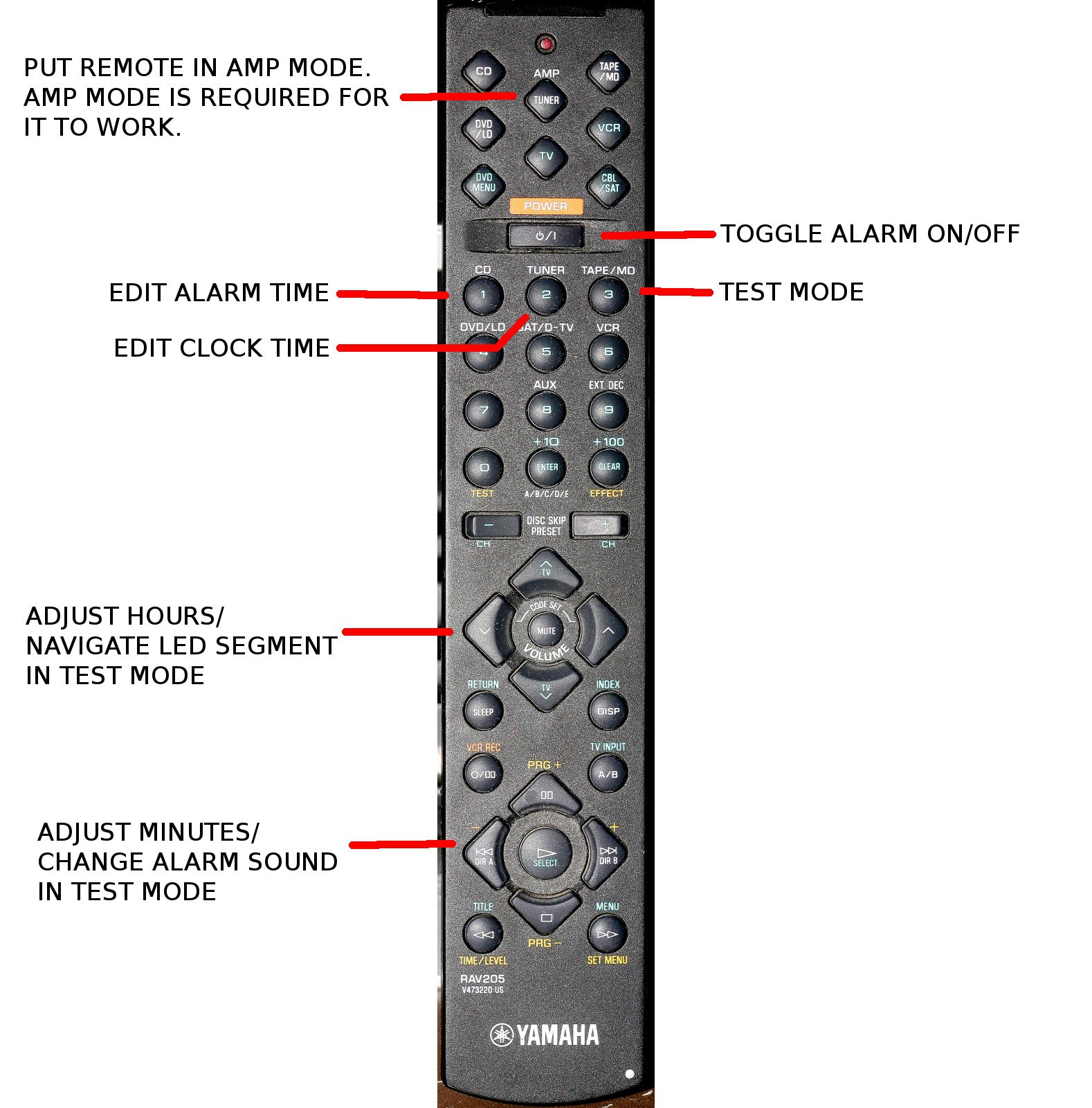
A year without commuting allowed the clock interface to never be used. With the return to commuting, the lion kingdom had manely forgotten how to set the alarm. It was time to document the control. This is the last Yamaha remote the lion kingdom will ever have & it arrived 20 years ago with a stereo that's long gone. The next remote once this one is lost will be completely different.
-
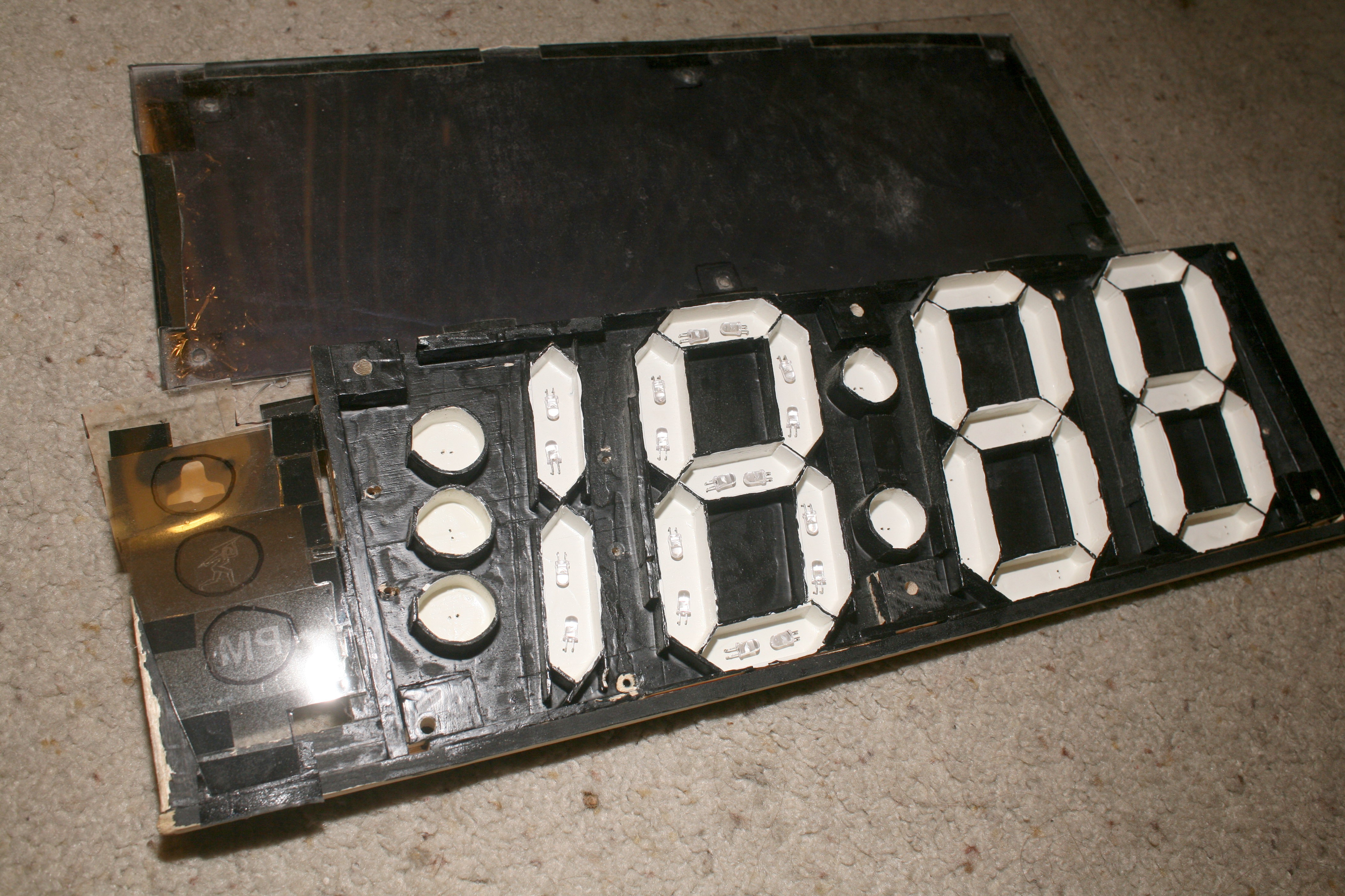
The remanes of Heroineclock I
08/16/2018 at 03:47 • 0 commentsThermometer II was made out of the known good LEDs from Heroineclock I, which left the original faceplate & questionable LEDs ready for landfill.
![]()
![]()
![]()
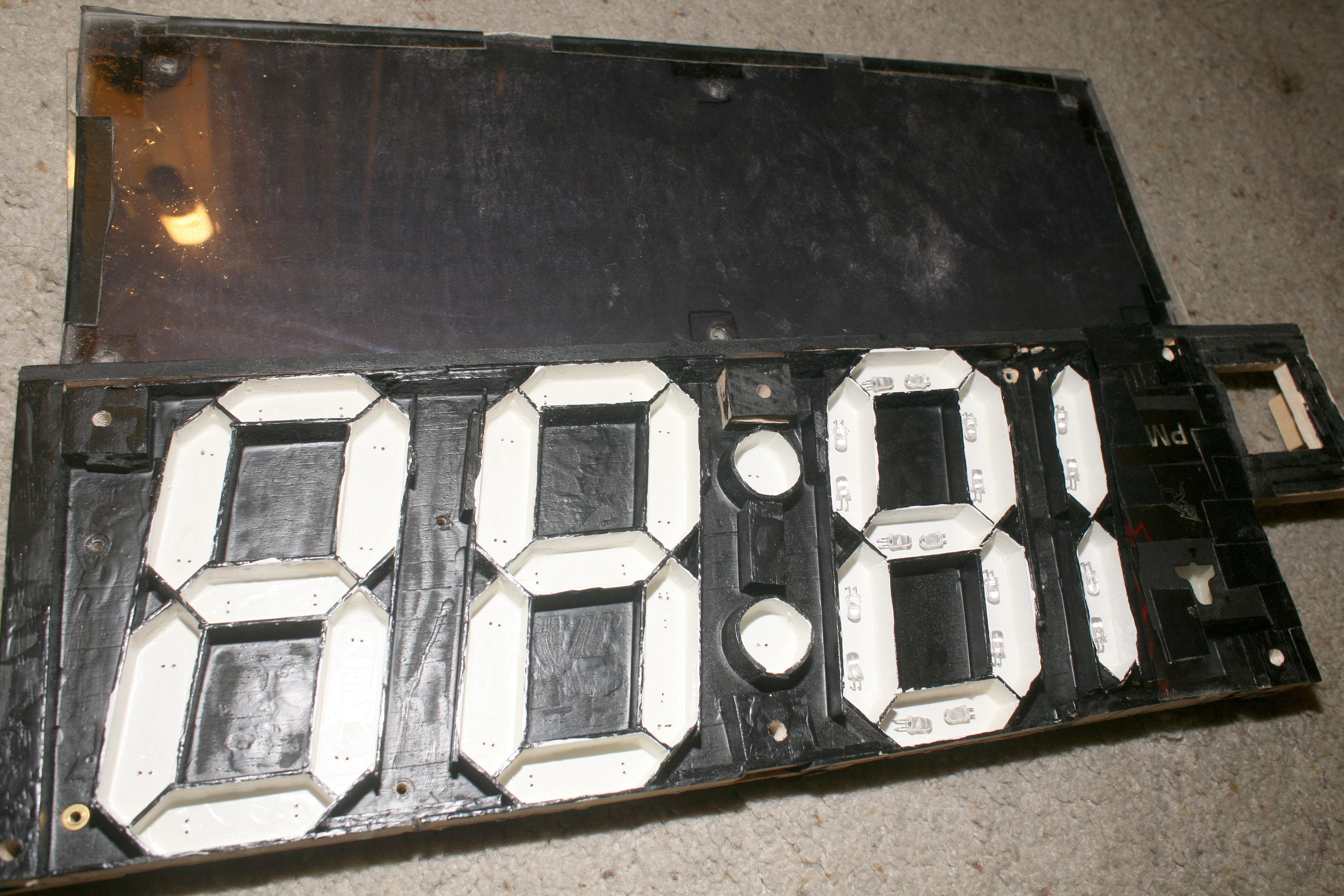
It was seriously overbuilt & had a lot more features. Was surprised to discover the plastic was covered in window tint to make it darker, while also losing some brightness.
![]()
It's long journey since being painted in 2004 had come to an end. The electronic section still has hope.
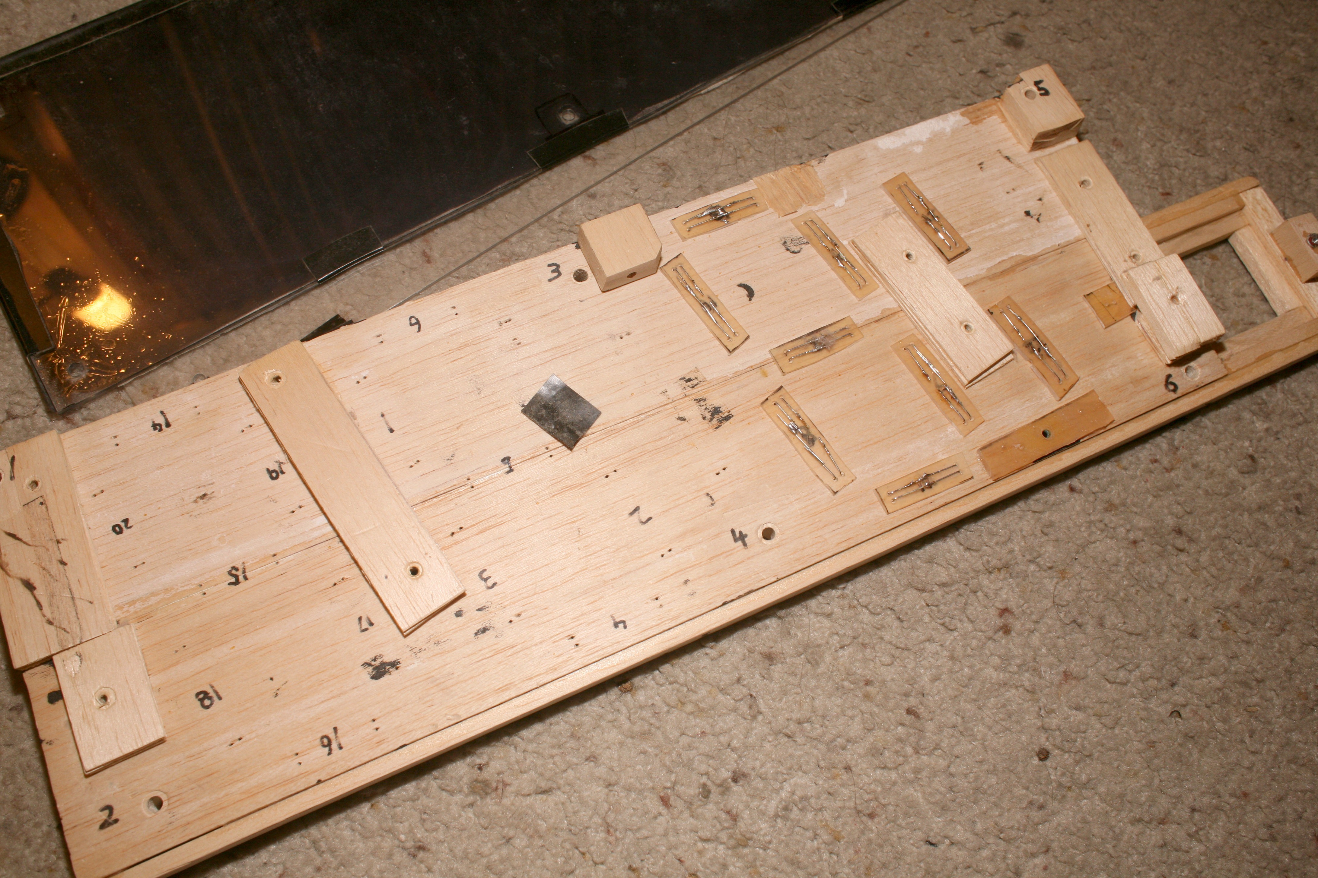
Whether the original balsa faceplate could be reused is doubtful. The lion kingdom doesn't foresee any way to afford a 2nd room. It's much bulkier than its size requires.
-
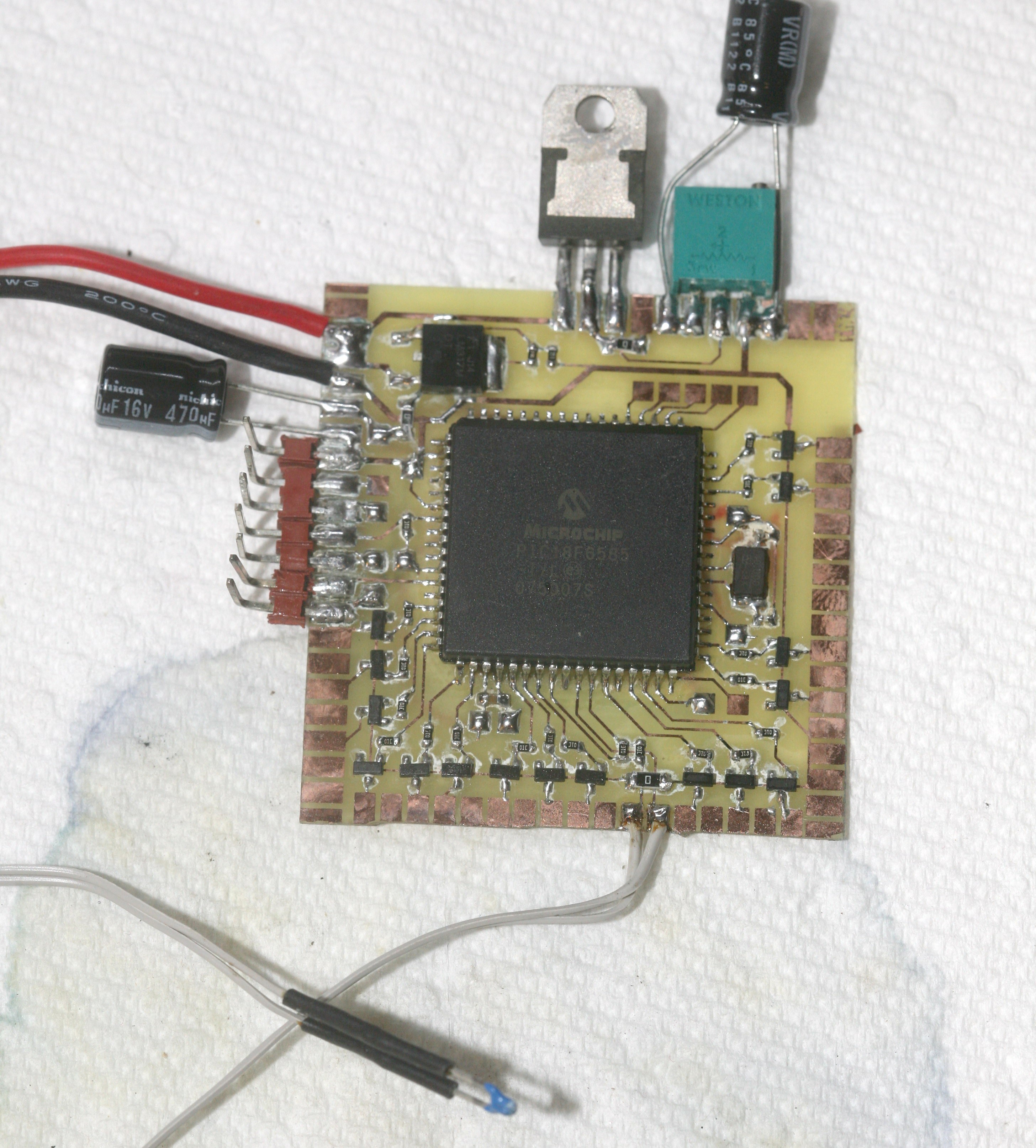
Thermometer II completion
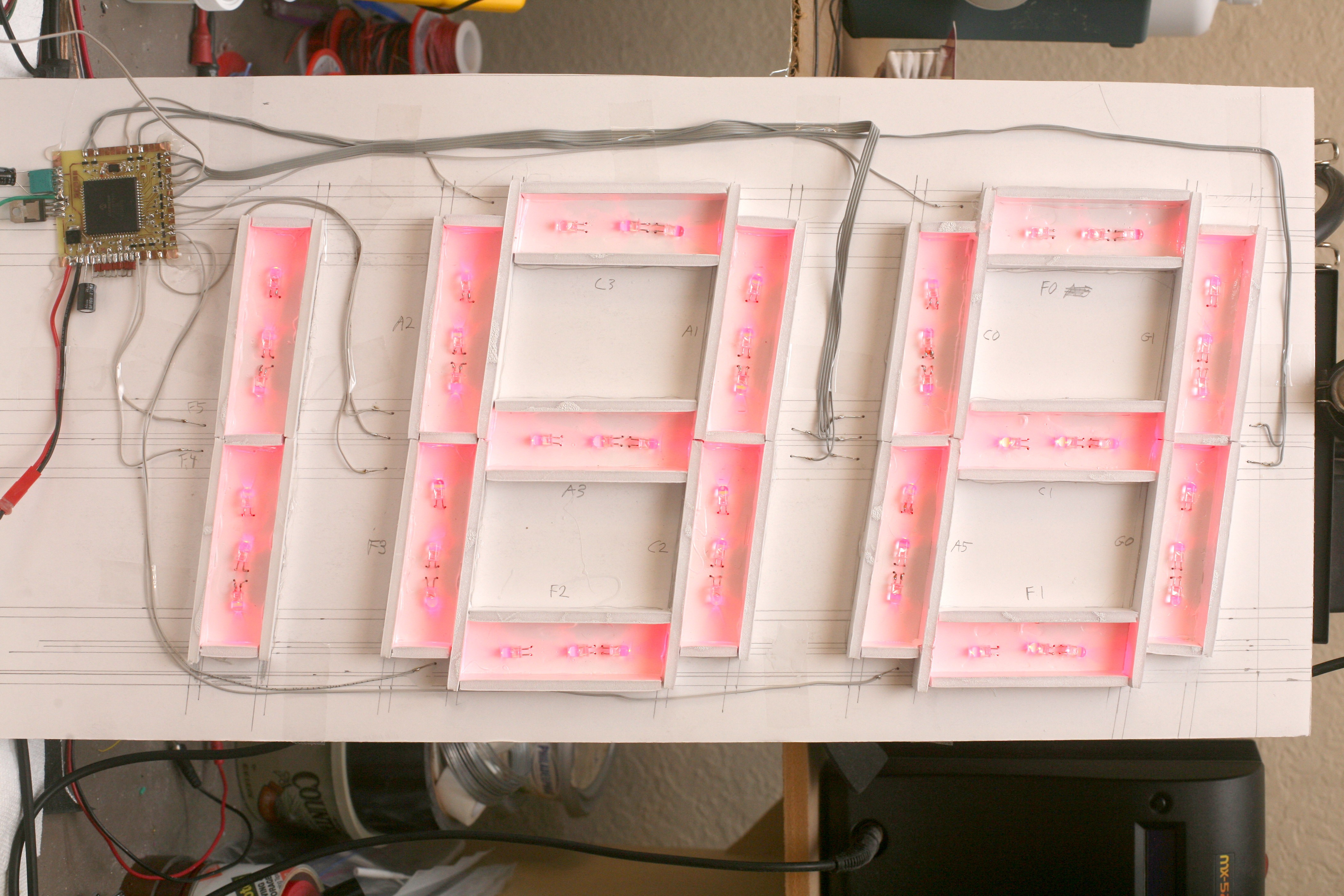
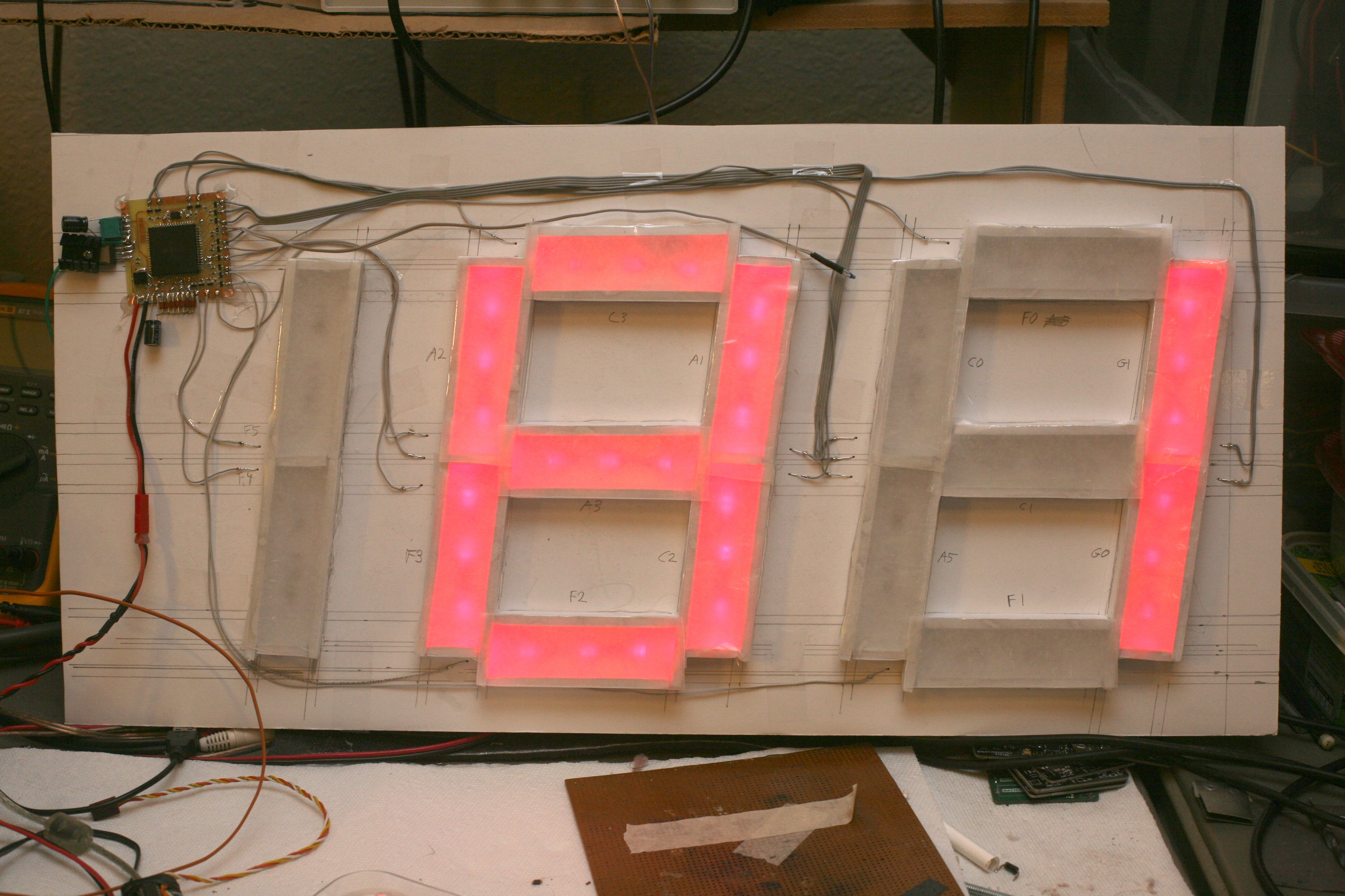
08/14/2018 at 08:34 • 0 comments![]()
![]()
![]()
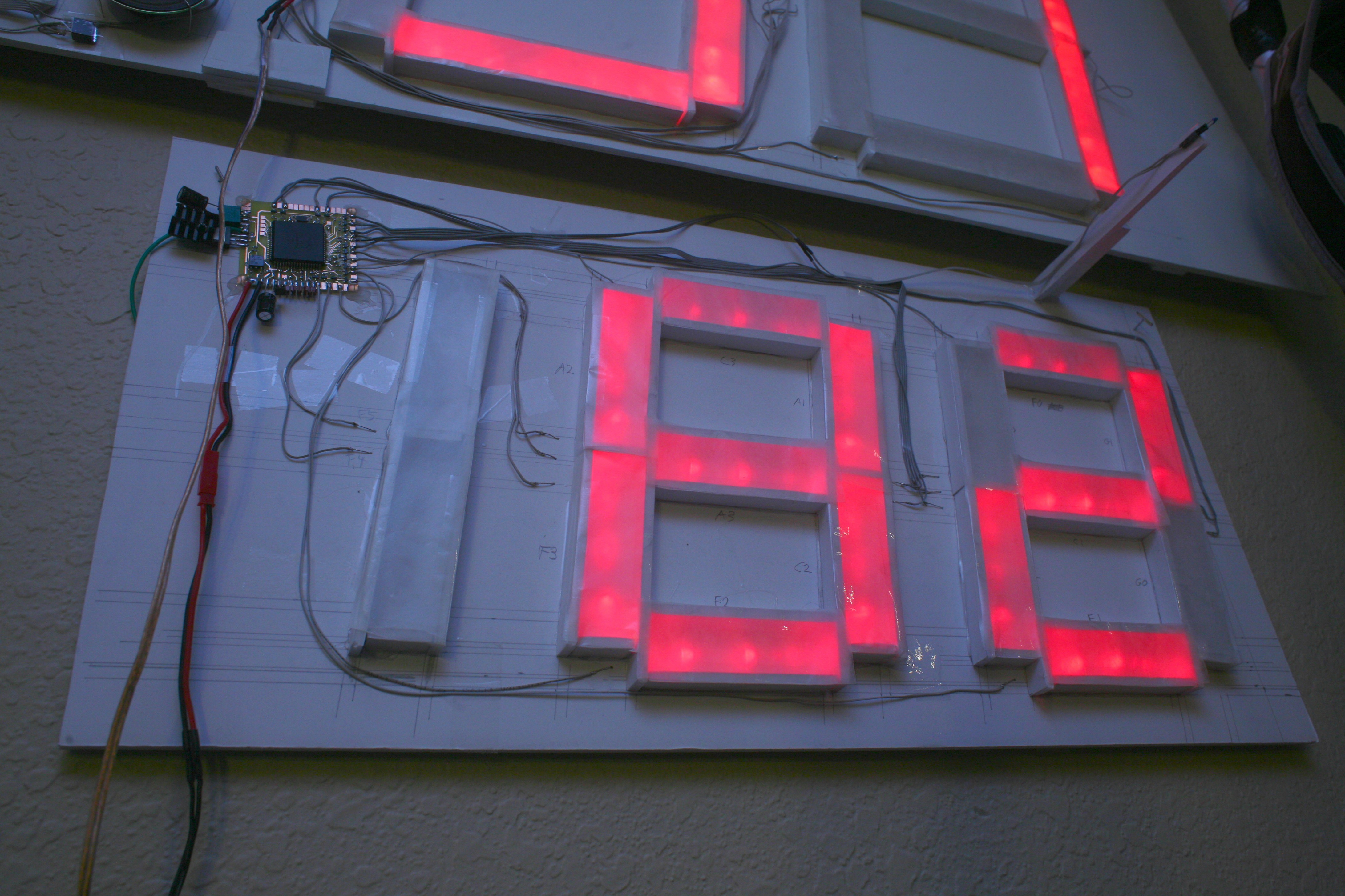
Be sure to label your GPIOs.
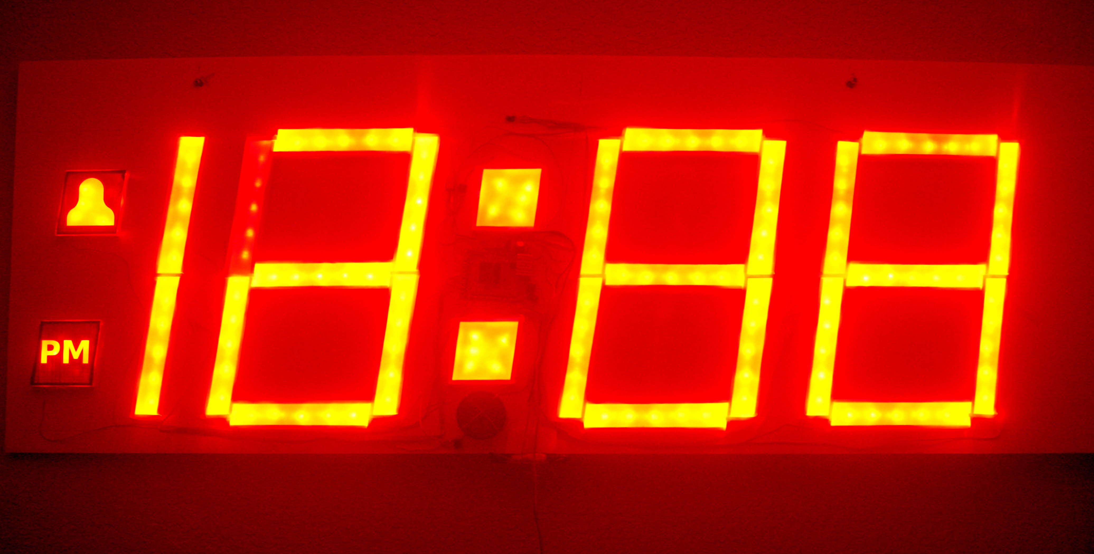
![]()
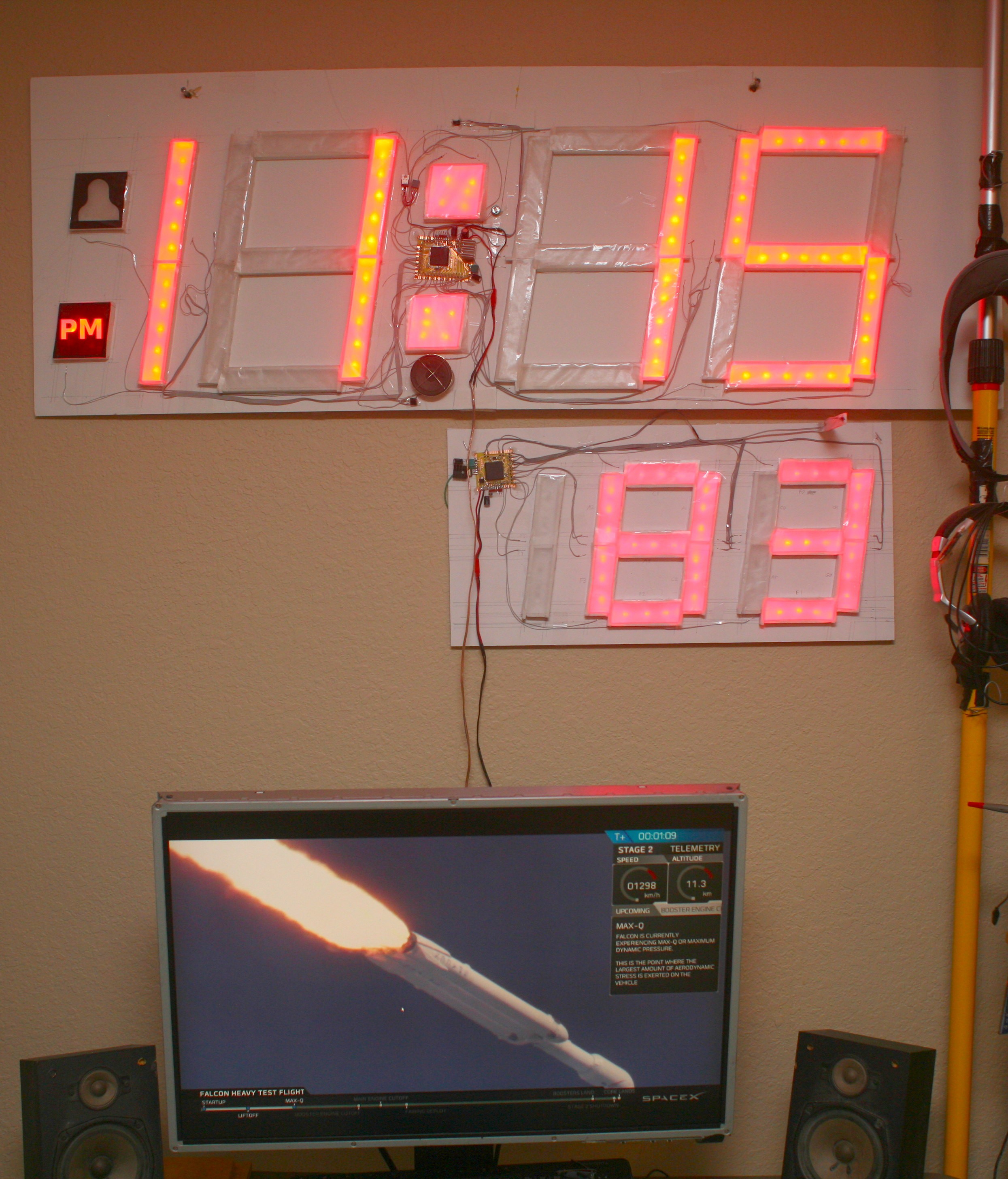
2 layers of wax paper, just like Heroineclock II were applied. The ancient LEDs were maxed out & it was still dimmer than Heroineclock II's minimum brightness. If you don't have any money, it says 81. If you have money, it says 72.
An accurate temperature reading is very very very hard because of the logarithmic resistance of the thermister combined with the logarithmic voltage from the voltage divider. Didn't realize how far off the circuit was until comparing it to the Fluke. Heroineclock 1 was calibrated only by testing ice & boiling water. Fluke measurements from ice & boiling water are way off of 32 & 212. Better results would be achieved by multiple GPIOs feeding variable current to the thermister.
The basic equation for a voltage divider gives reasonable ADC values near habitable
temperatures. A simple C program https://cdn.hackaday.io/files/284921219001728/temp_tester.c converted resistances from the data sheet to ADC values from the voltage divider. Though it had some experimental test values, the ADC values were predicted purely from the data sheet. This gave exactly the same temperatures as the Fluke, from 45F to 185F, accepting differences in thermal inertia.
To make a better video, the thermometer got a completely worthless test mode. The test mode was manely to measure its maximum current. It only used 140mAh with all the LEDs on. The PIC was clocked at only 10Mhz to reduce the power.
-
Thermometer 2 board
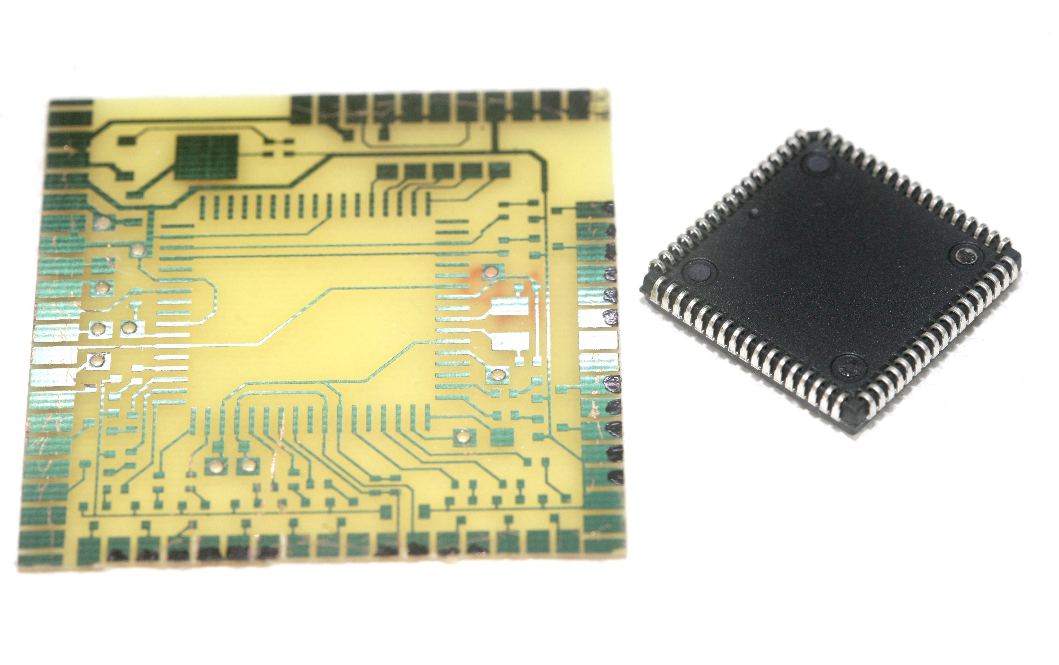
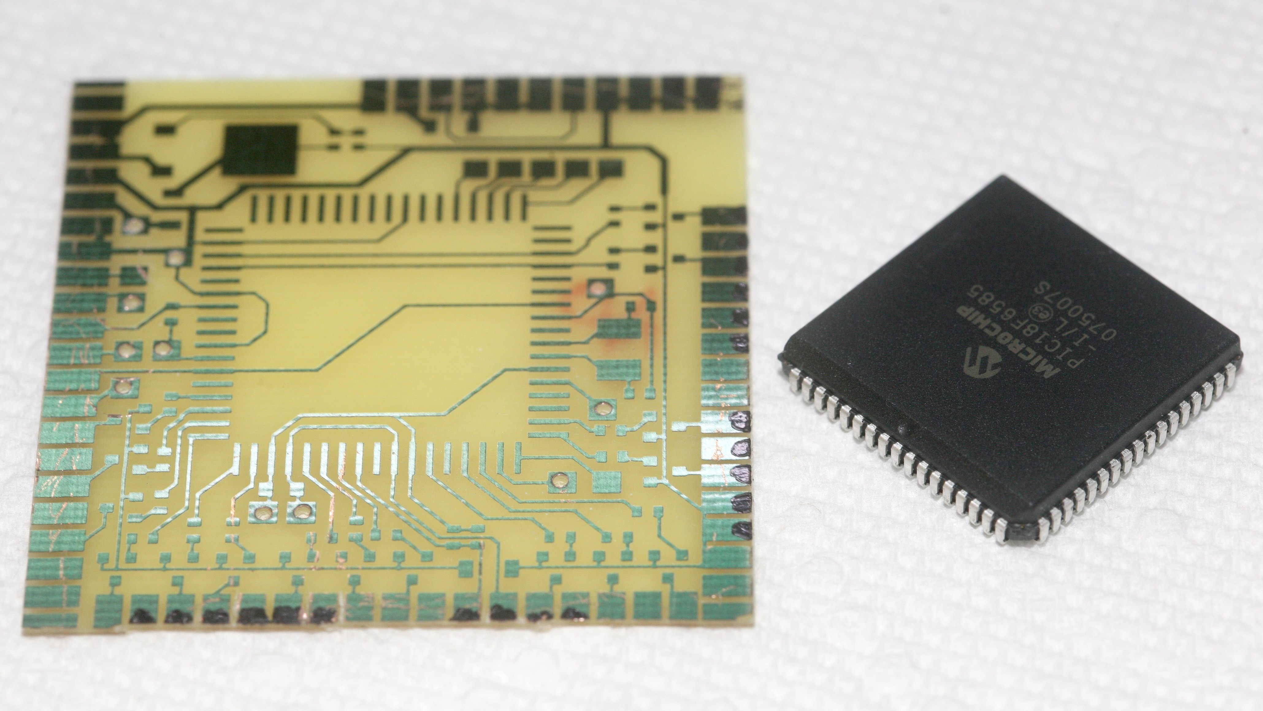
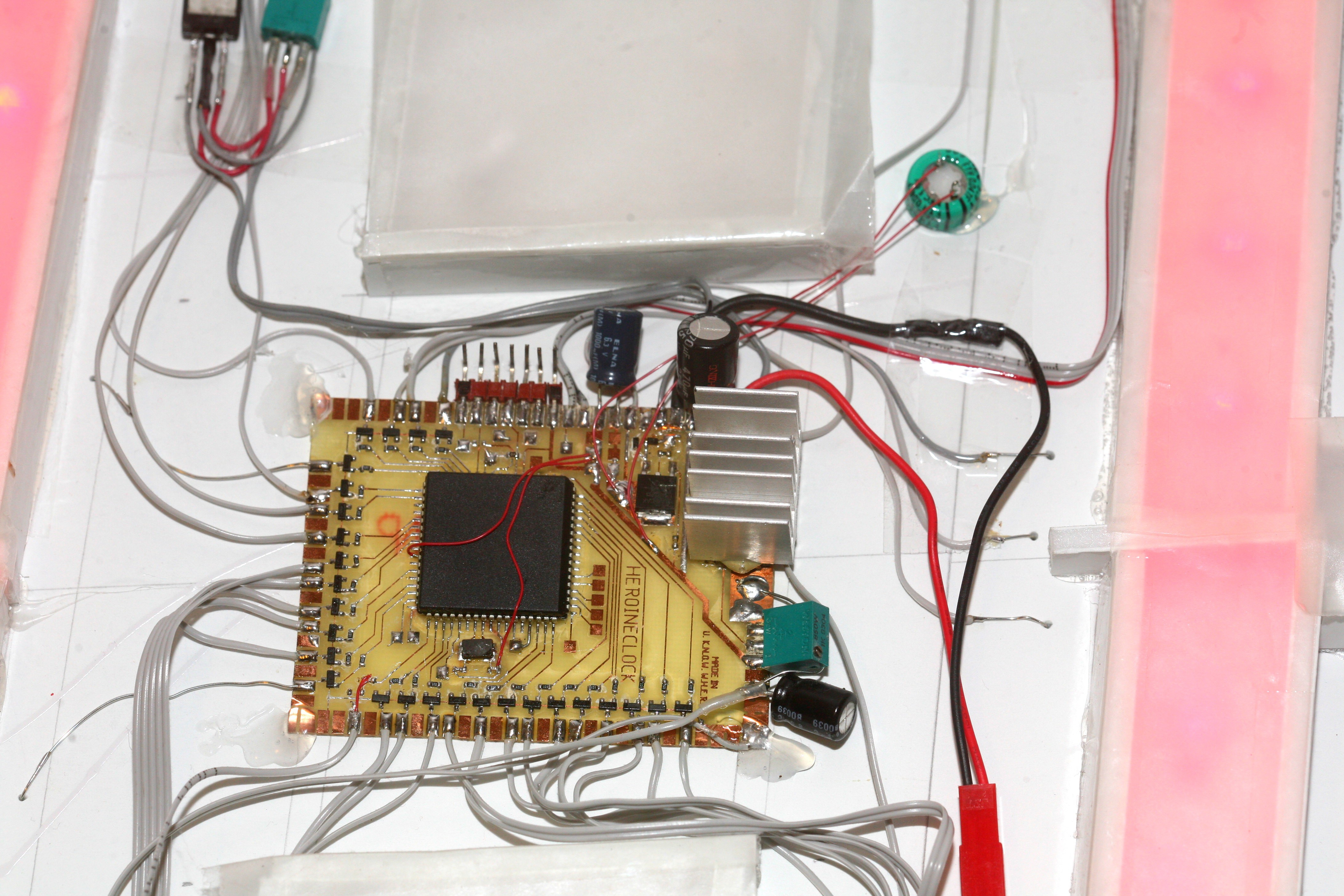
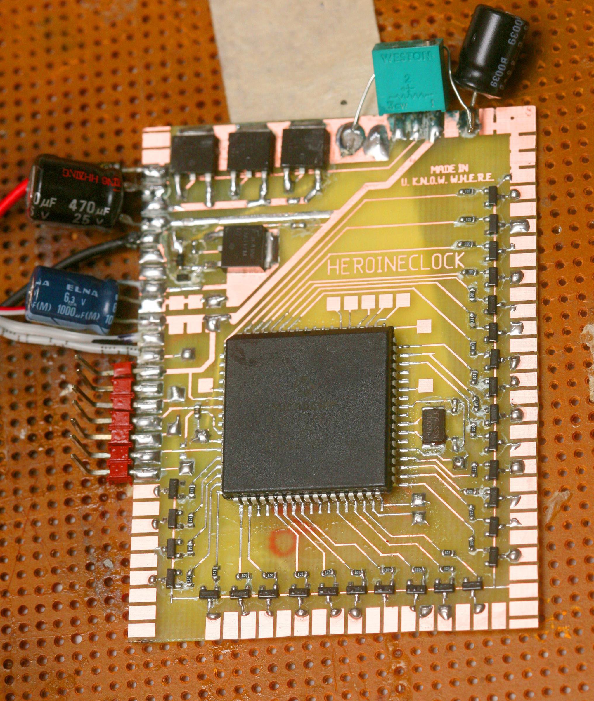
08/07/2018 at 20:39 • 0 comments![]()
![]()
![]()
The 1st home etched board since February rolled off the assembly line. Phones & raspberri pi's have made this fabrication extremely rare.
Those PLCC 68's are still things of beauty & joys forever. Should have used a much smaller chip, but the 68's came 10 years ago & were never used. They were meant for building heroineclock II in through hole mode, but all through hole boards of that complexity were replaced by surface mount. It's totally pointless & expensive to use them now, outside of vanity designs. It'll be in full view of the apartment until the lion kingdom dies.
It occurred to the lion kingdom to make the segments fade on, instead of smashing on like LED brakelights. It might make it easier to sleep & give it an edge over Chinese shit. It would also feel like slowing down the aging process if the numbers didn't quickly change.
Would still have to bang the LEDs on when playing sound. PWM needs to get above 200Hz. The trick is fading slow enough to not wake up the lion, to not look like an incandescent light & yet fast enough to have a useful on time. Having said that, sleeping is the only time a lion even sees the digits changing. Once you get used to it, it doesn't matter.
![]()
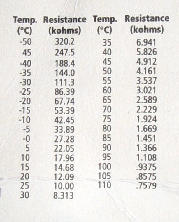
The https://hackaday.io/project/159267-moving-the-dvd-archive-to-an-8tb-hard-drive DVD archiving project yielded the original table for the original thermister. 20 years ago, you could obtain a bare thermister just by walking 2 miles, no shipping costs or 1 week delay. 30 years ago, someone who lived outside China even knew what a thermister was.
Useful range would be 5k - 30k. Heroineclock 1 used a carefully tuned op-amp to span the entire ADC range. Modern designs just wire the thermister in series with a resistor. A 10k gives 0.45 - 3.75 on the voltage range. A 5k resistor gives 0.83 - 4.29.
-
Thermometer II
07/14/2018 at 20:51 • 0 commentsThe original heroineclock had a thermometer. It could show temperature fulltime or oscillate between time & temperature. It oscillated painfully for 10 years. It could be resurrected as a fulltime thermometer, but it uses too much power. There are 33 LEDs known to be good in Heroineclock 1 & 23 spares of Heroineclock 1's vintage. A temperature display of Heroineclock 2's size needs 80 + at least 5 spares.
The framework of Heroineclock 1 could be left intact, with all the electronics replaced, LEDs rewired in series. Heroineclock 2 left behind enough transistors to do the job. Voltage regulators from Heroineclock 1 could be reused. A slightly larger display could be made with 3 LEDs per segment.
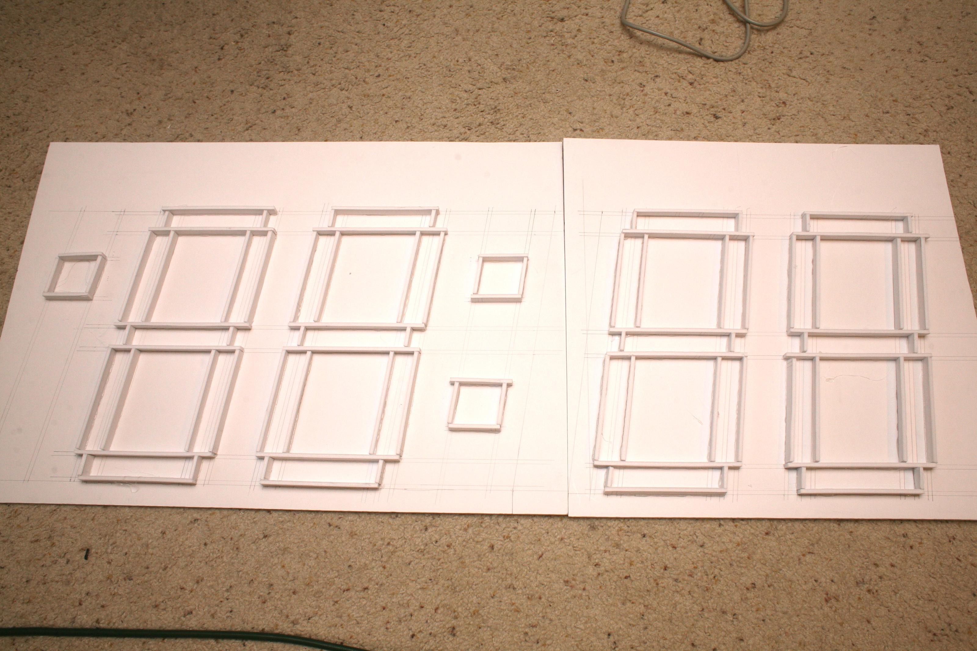
![]()
3 LEDs per segment limited the new display to 8" tall. Younger lions could make out 6" tall digits from anywhere in the apartment, so old lions might be still able to read it with a bit of effort.
The LED count limited it to 0-199 in Fahrenheit. Imperial is still the cheapest unit to display, as much as binary imperial would be even cheaper.
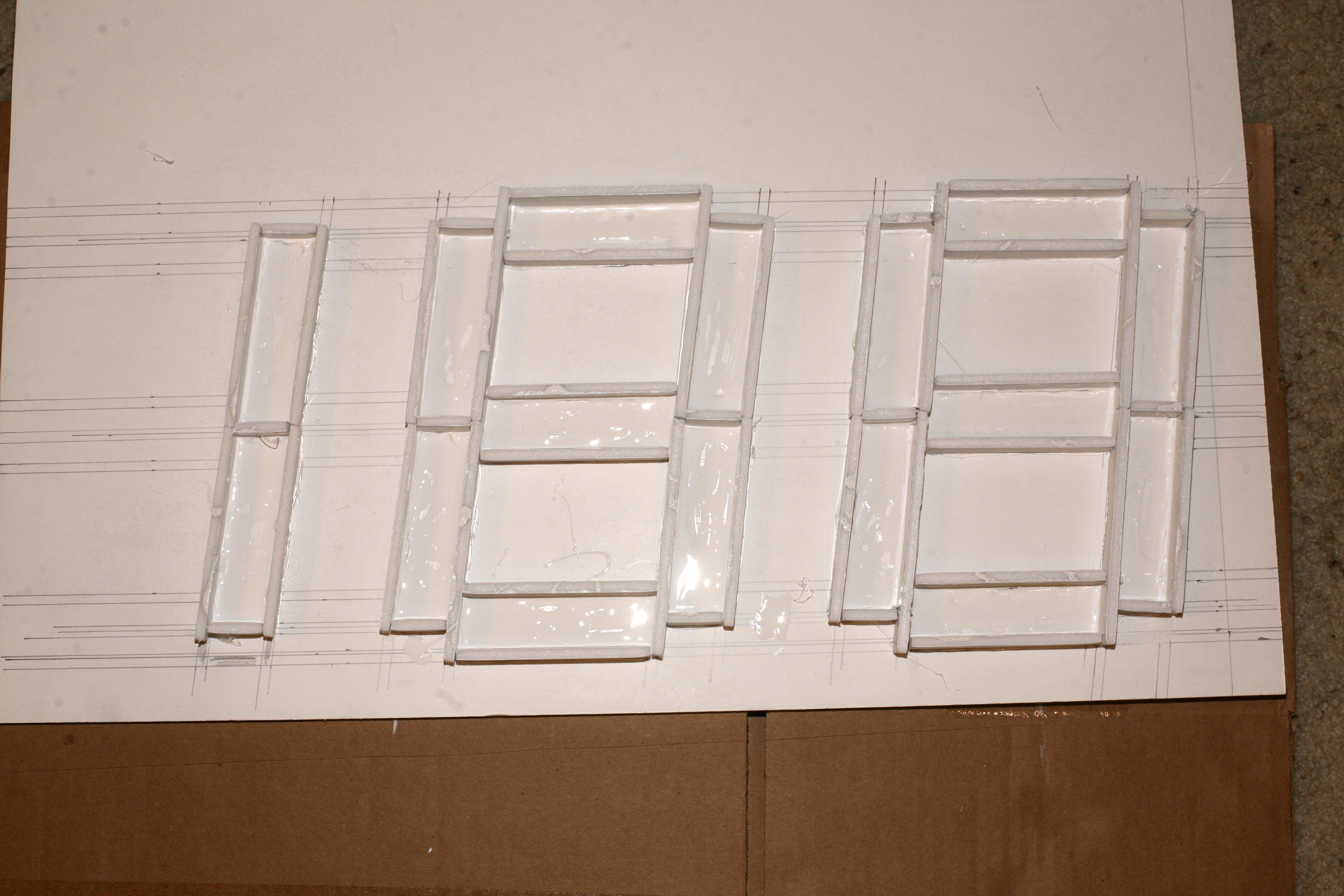
Lessons learned from Heroineclock II were applied to thermometer II.
Far fewer pieces of foam were cut for each digit. The foam length was limited by the amount of hot glue which would stay hot.
Apply hot glue to the paper side of the joints, not the foam side. It melts foam so nothing fits flush. Don't do what Adam Savage does.
Glue middle segments of each digit first, then work outward. This way, segments won't end up being too long for the remaneing space & the digits will naturally overrun the outlines.
Try to hold the segments vertical until the glue sets. The glue fills in the gaps from lousy cutting.
Measurements don't have to be crazy accurate, because the cutting & gluing is terrible anyway.
-
LED replacement
07/07/2018 at 06:36 • 0 comments![]()
It was 1st documented in Nov 2017 that a segment had died, as they always do. Lions wait as long as possible, in case more segments quickly followed.
![]()
8 months later, all 5 LEDs had to be replaced. The lion only ordered 5 replacements. The next bad segment will require using higher voltage ones with the higher voltage regulator or another $20 digikey order of yet another voltage. Not easy to have any surplus, since China only does 1 run of each LED design.
Also replaced the backup battery with a 45000uF cap. It feeds the regulator's feedback resistors, so it only lasts a second. It's good enough for glitches & there's nothing to configure on the clock. The backup battery was worthless, since the power went out often, for over 4 hours & a charging circuit would have been expensive. Without a charger, it was easier just to reset the time than disassemble it.
During the year without the segment, telling time was still possible. It made the lion kingdom wonder, with all the funky binary, octal, hex, flipper clocks, what is the minimum number of segments required for the minimum useful precision? It's 11 segments, 5 bits for the hour in binary, 6 bits for the minutes in binary. You'd have to be a savant to decipher it, or a candidate for a SpaceX job.
Binary coded binary is still too hard. Hex hours with base 10 minutes would allow dropping 2 hour segments & still be easy. It might be hard to remember the minutes were base 10.
-
The Video
12/07/2017 at 22:21 • 0 commentsThe video
-
Construction
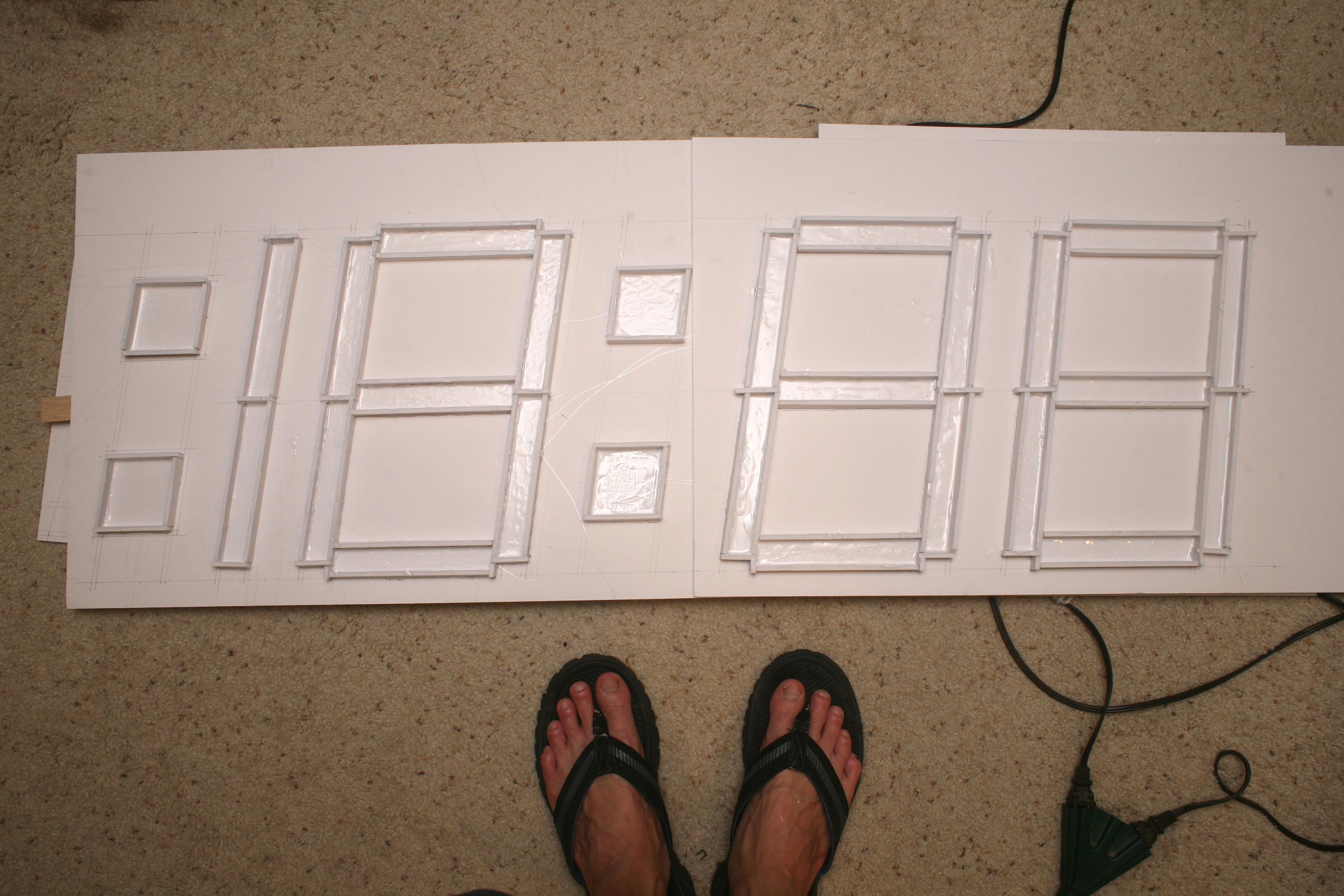
12/07/2017 at 22:12 • 0 comments![]()
The first pattern was drawn.
![]()
The 1st pattern was a failure. There were gaps in the segments.
![]()
The 2nd pattern was a failure. There were still gaps.
![]()
Final pattern, with paint for brightness.
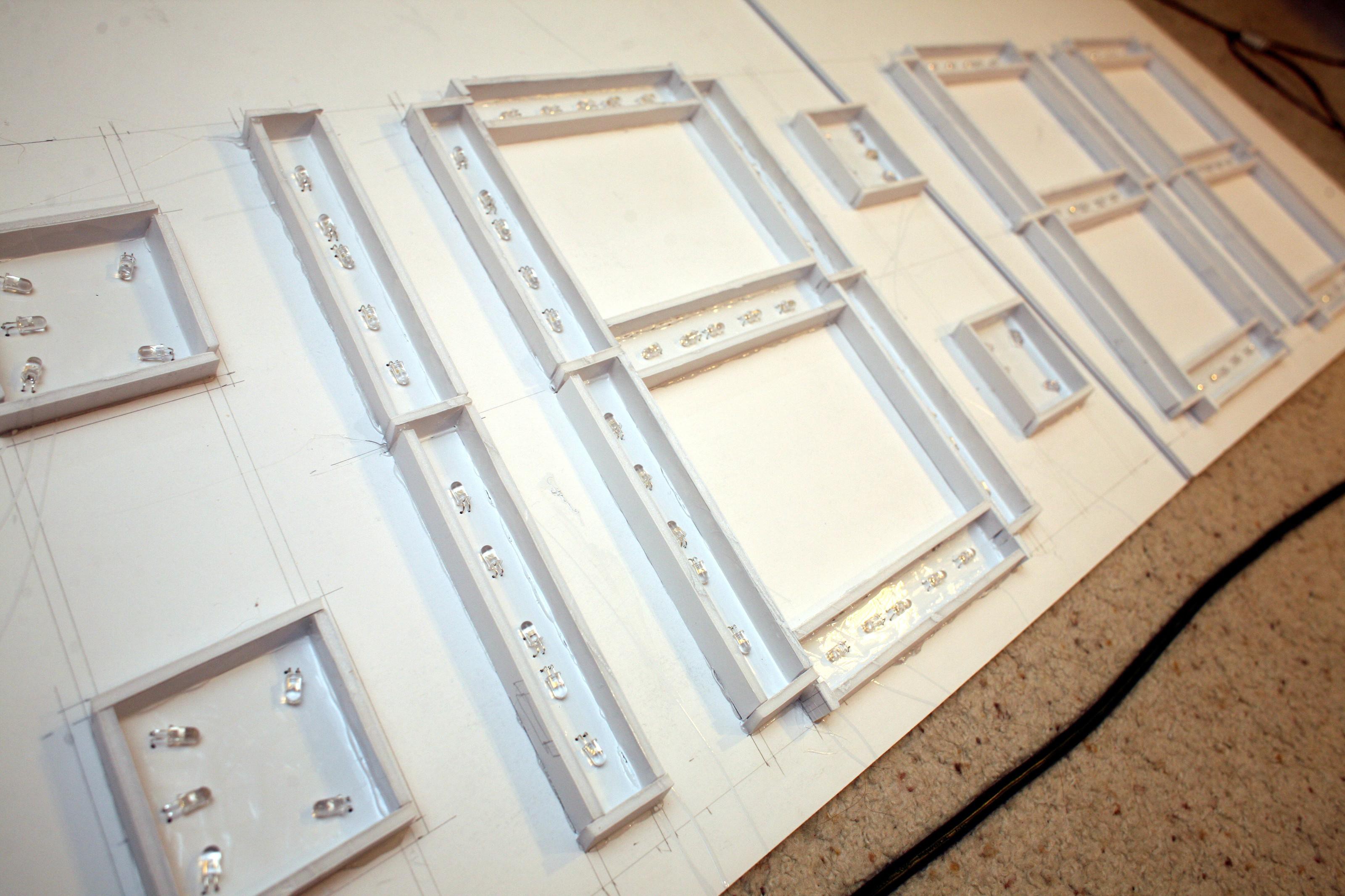
![]()
Completed LED installation.
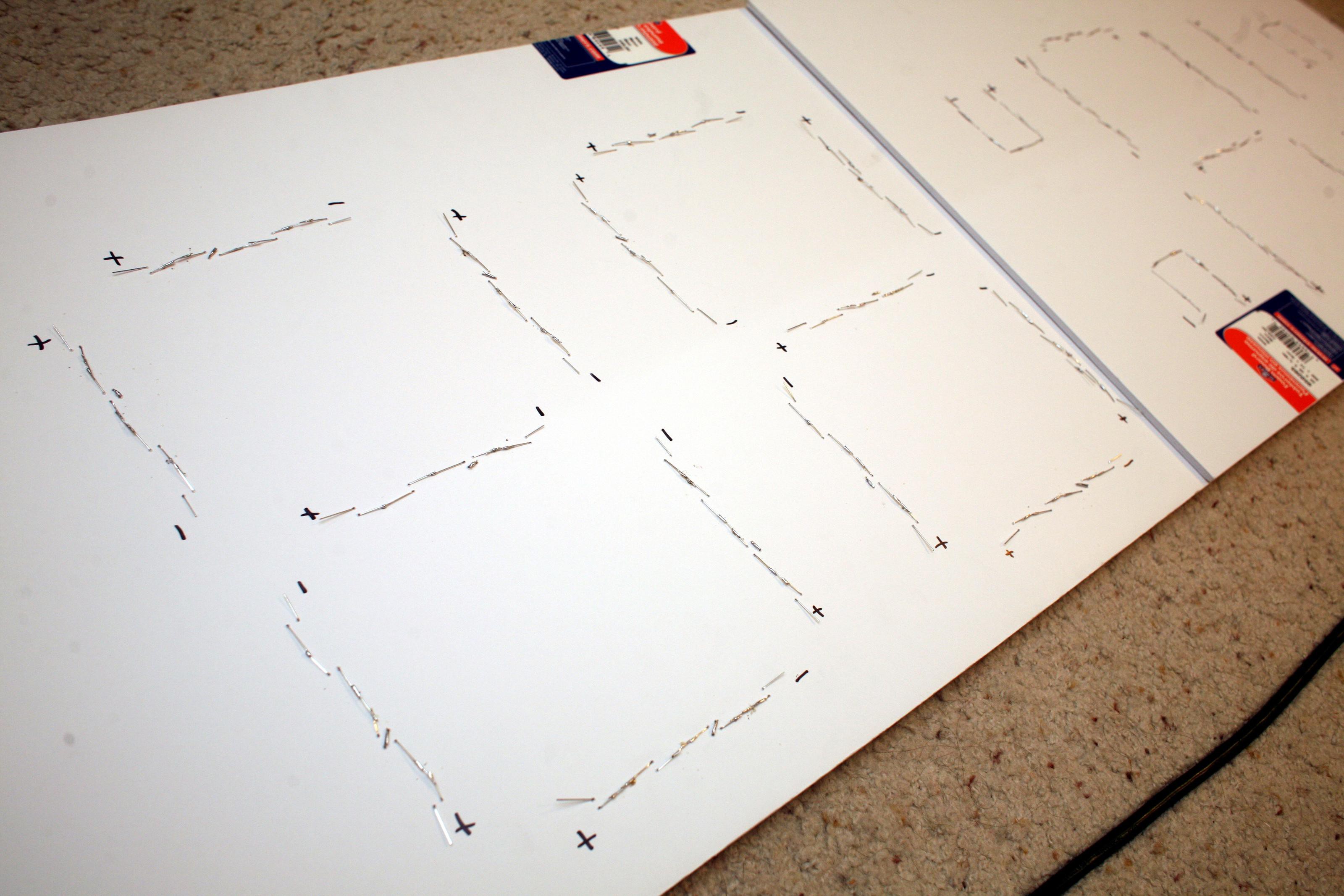
![]()
Soldering & labeling of all the LEDs.
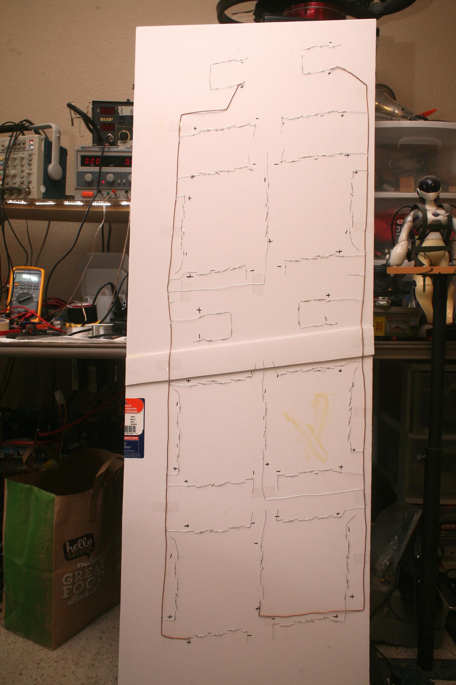
![]()
Complete back wiring
![]()
Complete board with lots of defects.
![]()
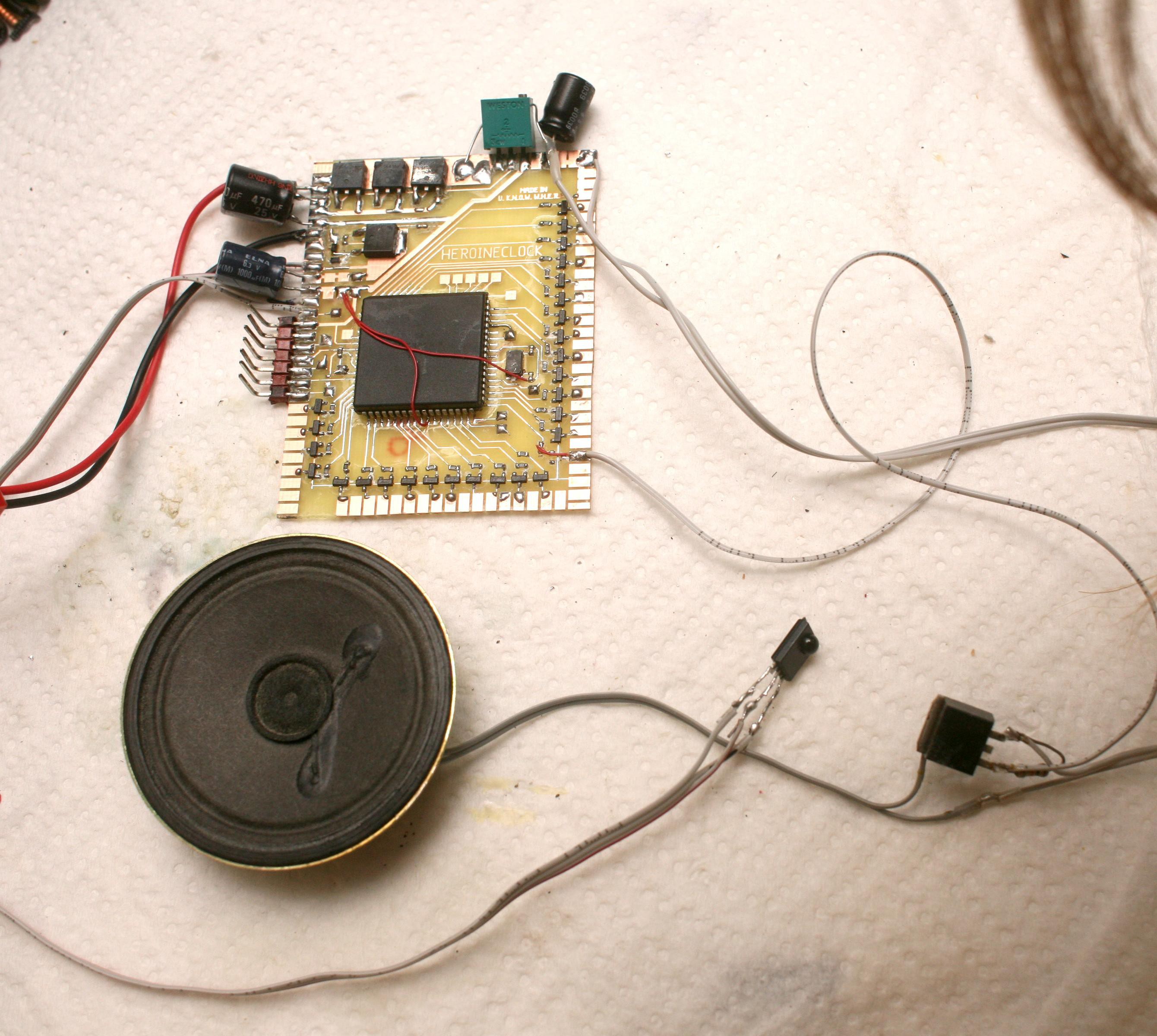
All the ground pins had to be grounded for it to work at all. The speaker needed a MOSFET with more power.
![]()
1st light of the LEDs powered by the mane board.
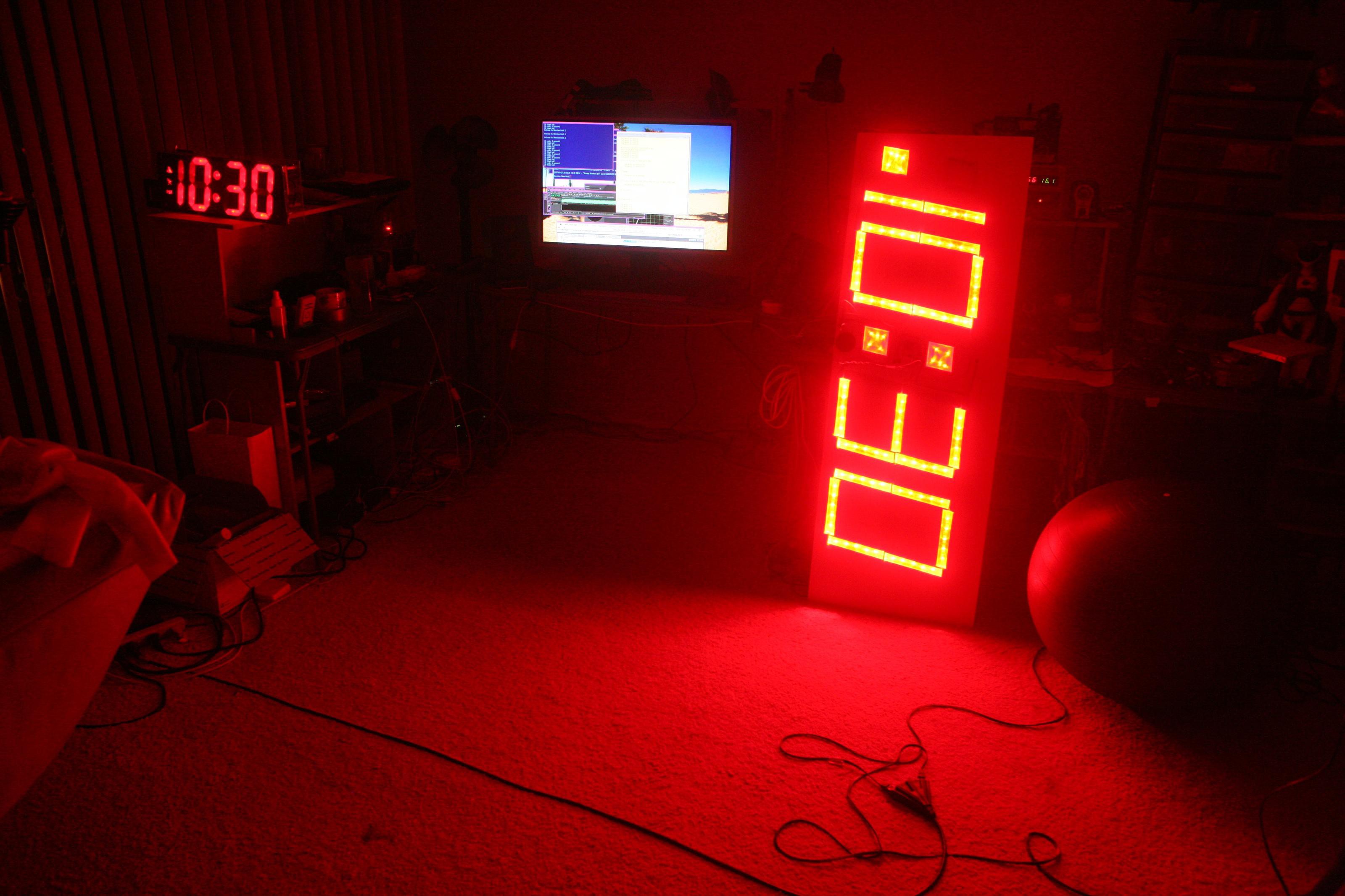
![]()
Maximum brightness, showing the 1st time display. Voltage had to be reduced to the minimum in order for it to be dim enough to sleep by.
![]()
Each segment was individually covered in 2 layers of wax paper. Laser printed transparencies covered the icons.
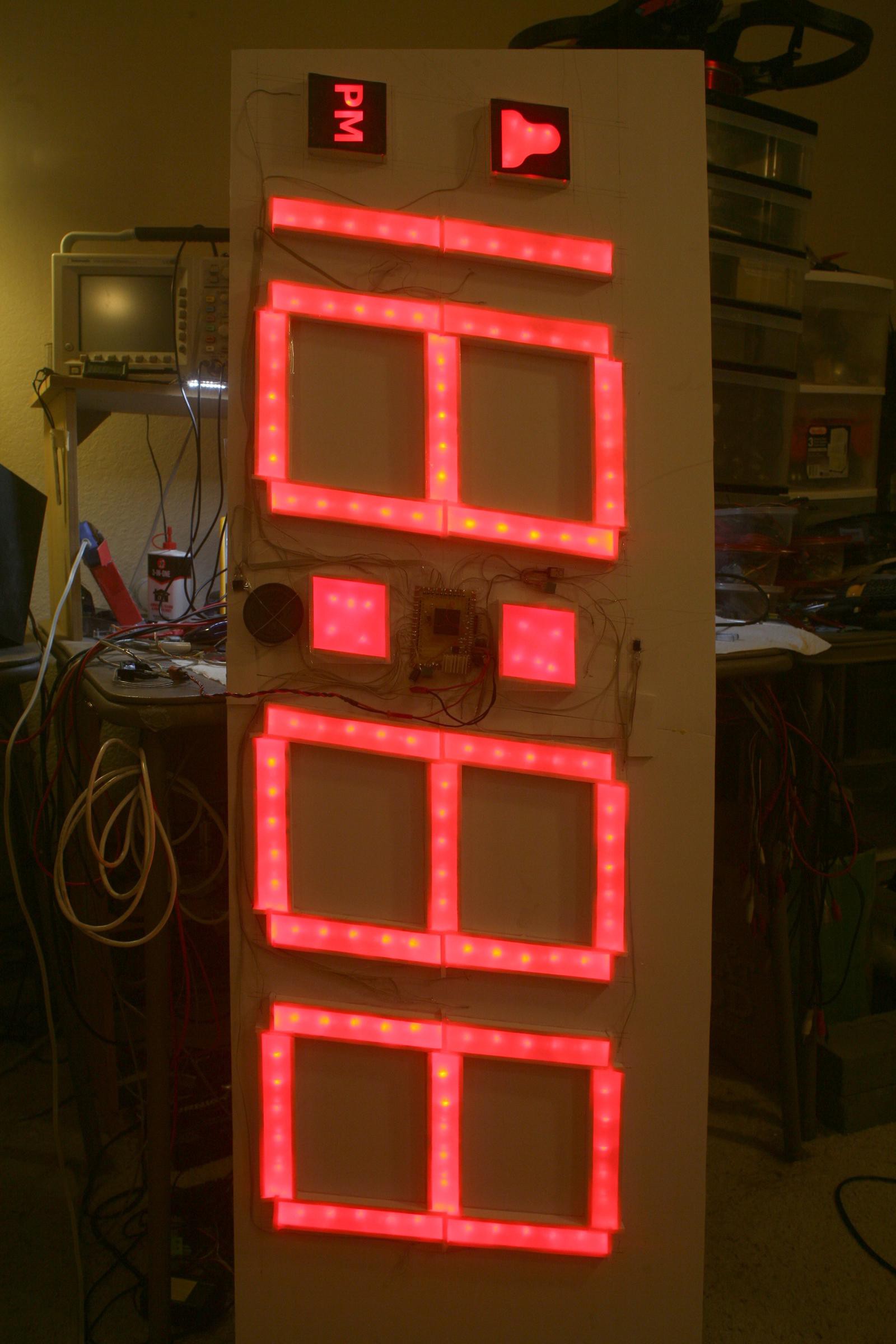
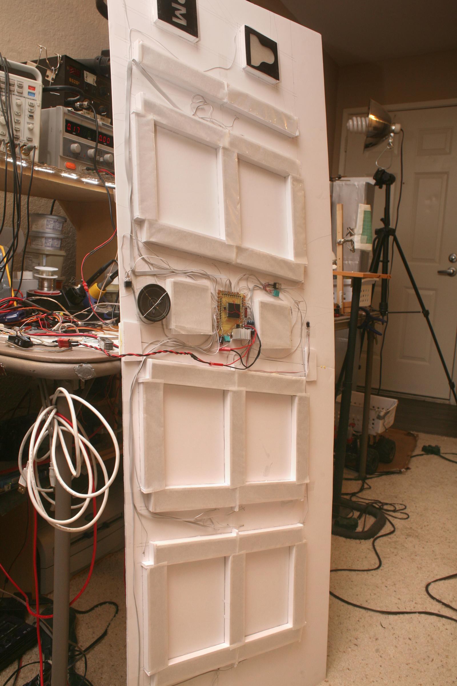
![]()
IR sensor, speaker, mane board strapped in. Every segment has its own ground wire to the mane board. A 2nd voltage regulator powers the colon. That contains 10 old LEDs which required higher voltage.
Heroineclock II
Giant clock from a PIC18F6585, 135 cheap LEDs, foam core posterboard, hot glue, lots of hot glue