The problem with modern headsets is you can't hear your own voice or determine if the microphone is working. There is absolutely no way to monitor the headset microphone with phone software. That was attempted long ago. The best solution was a software loopback which delayed it. Android allowed nowhere close to the latency of ALSA, despite all the hardware being there.
Then, there was the idea of using a confuser soundcard to mix the microphone with speakers for monitoring, but the microphone would have to be split & sent back to the phone. To keep emissions from the phone out of the confuser soundcard, there would have to be an RF choke & voltage following amplifier. It would need some kind of mute button which didn't make pops. Android's mute button with non sensical screen blanking is useless. There would be powered analog electronicals no matter what.
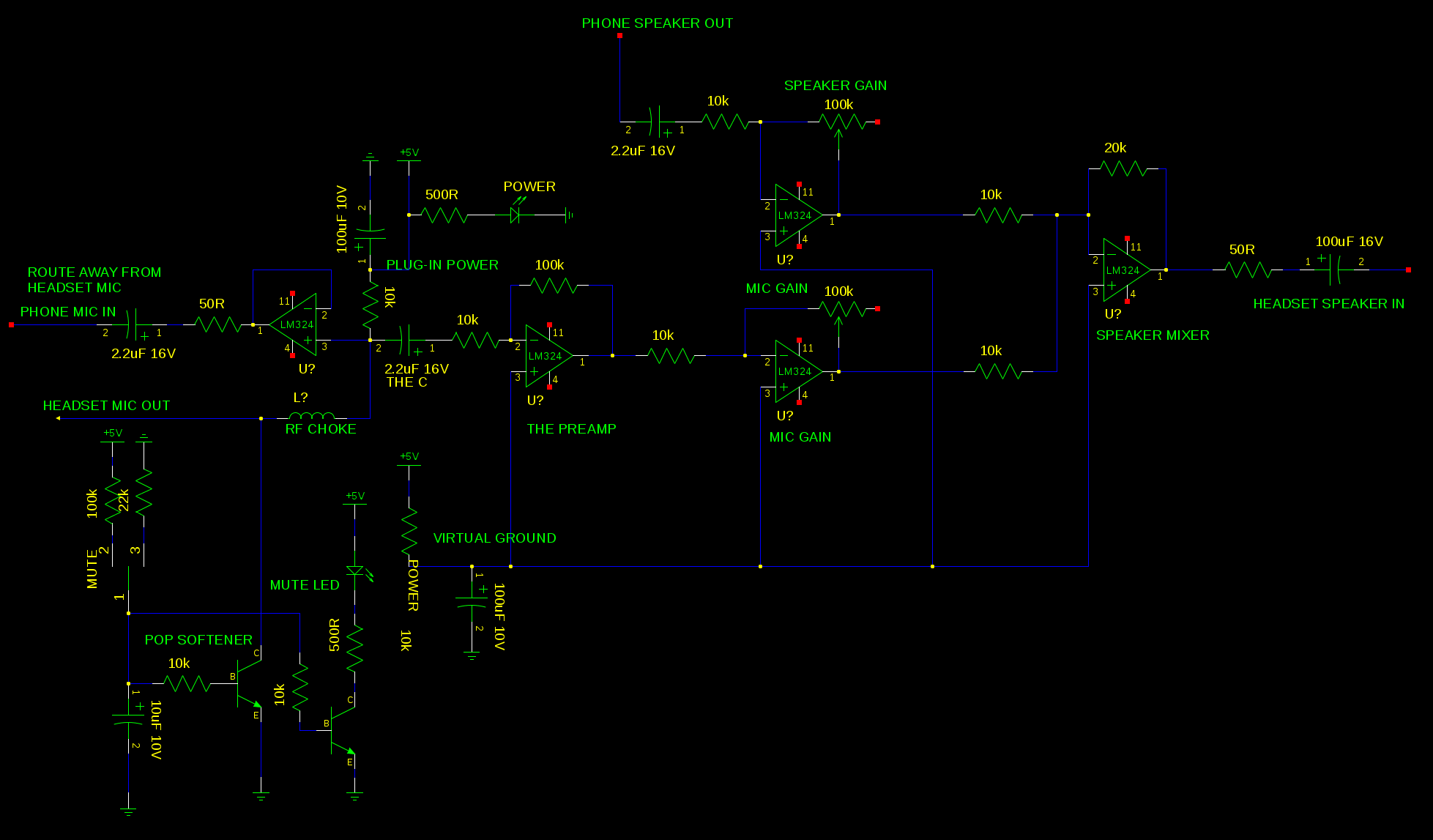
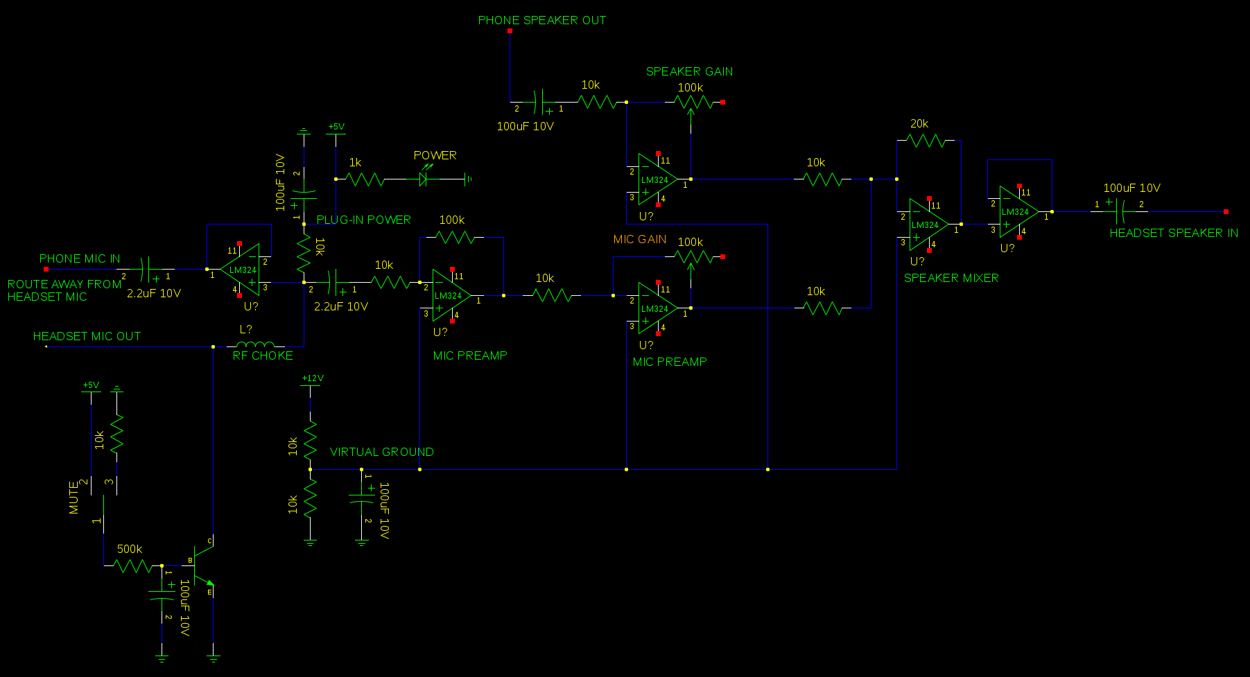
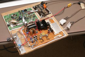
This was 1st solved in 2012 with an analog headset monitor. It was a very large circuit board for what it did, using multiple LM324's to mix the microphone with the speaker output, power the speakers, & isolate the microphone from the phone. The original also had a large inductor to shield the microphone amplifier from the phone's RF emissions.

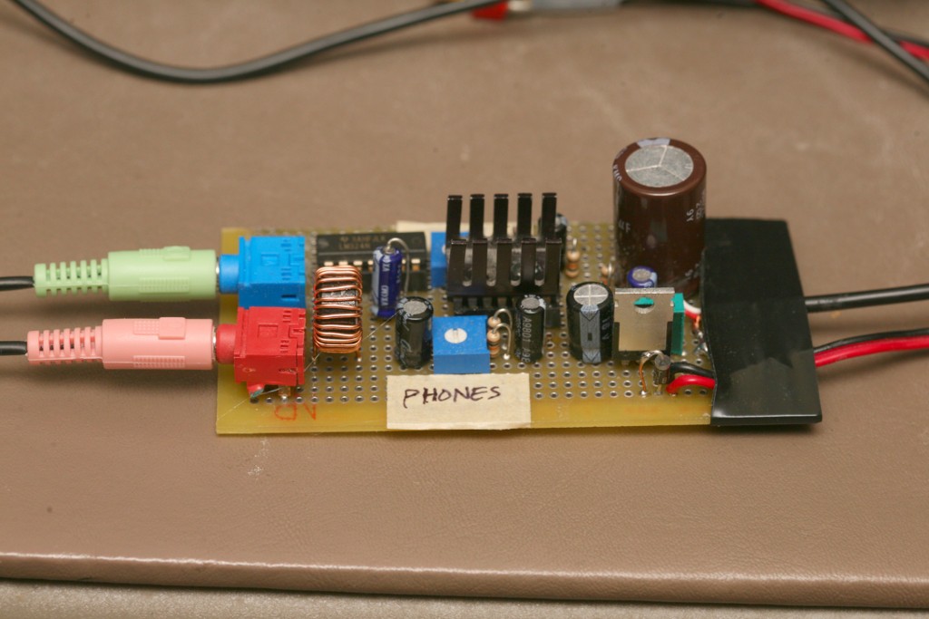
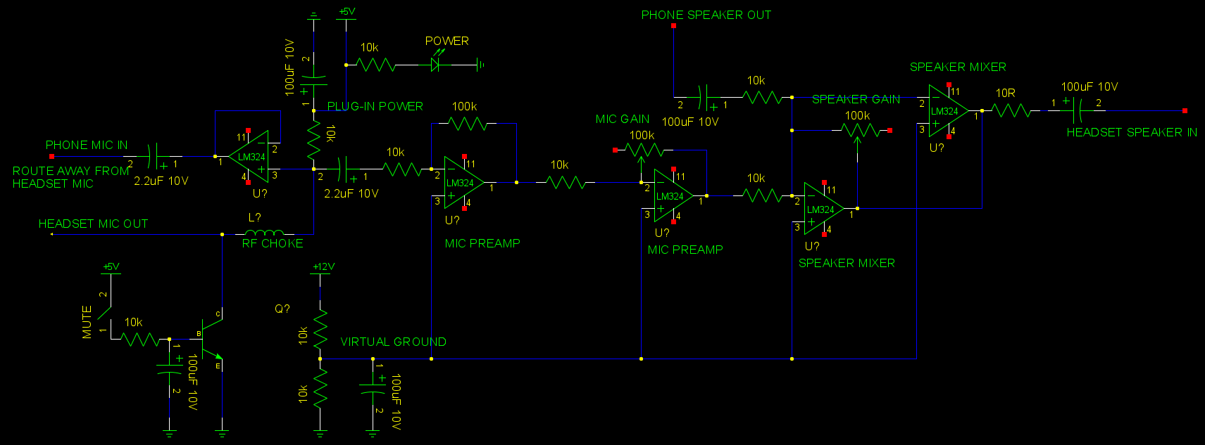
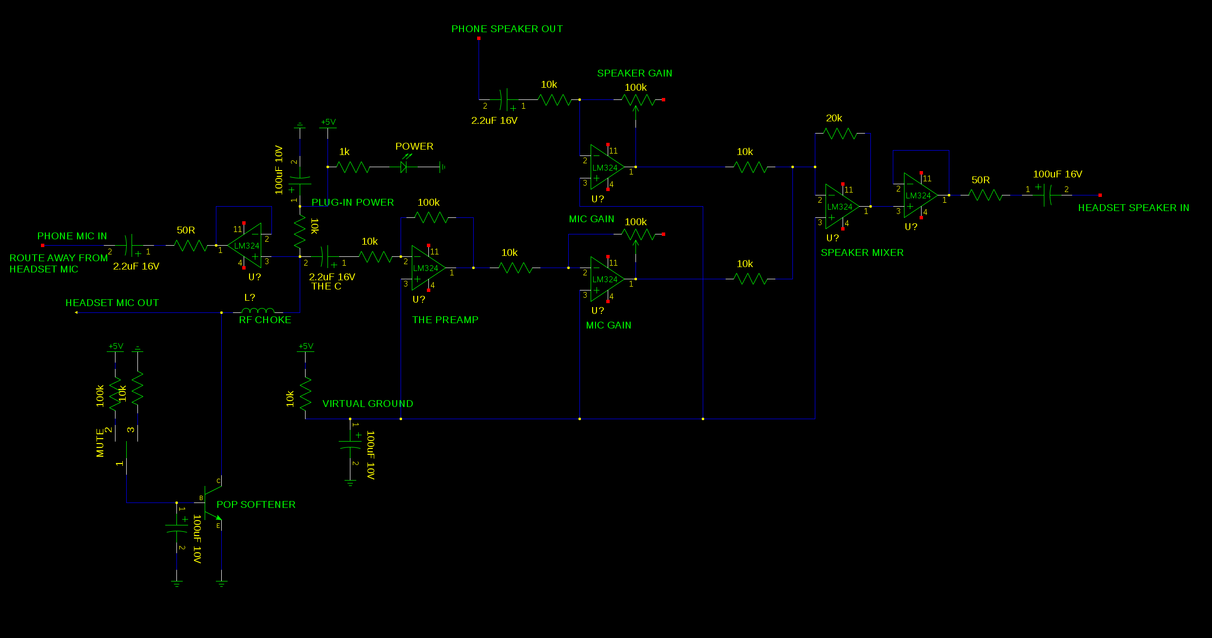
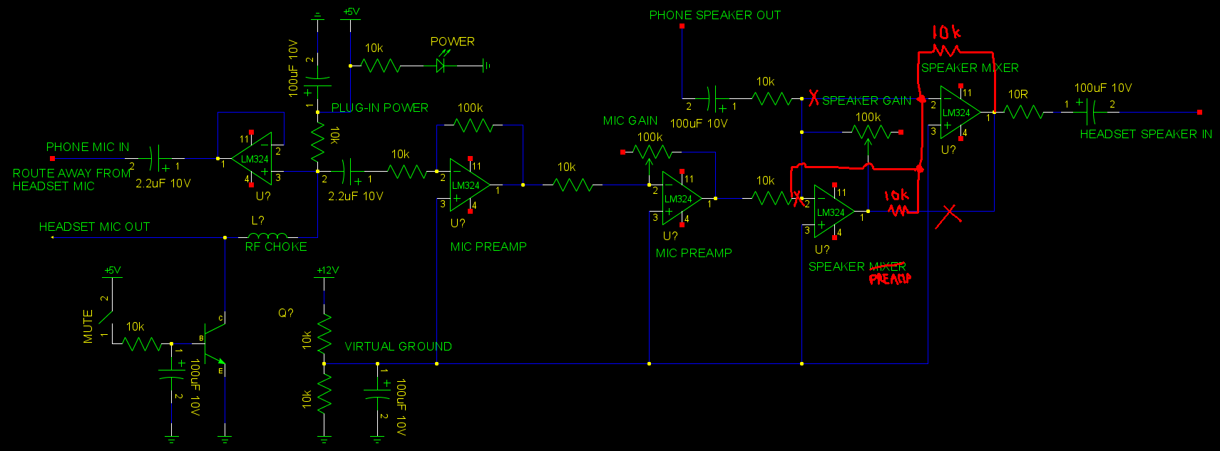
8 years later, it had grown into a quite complicated circuit. The mane additions over the years were an LED to show when it was on & a simple transistor to mute the microphone by grounding it. It also needed a resistor after the speaker mixer to prevent op-amp oscillation.
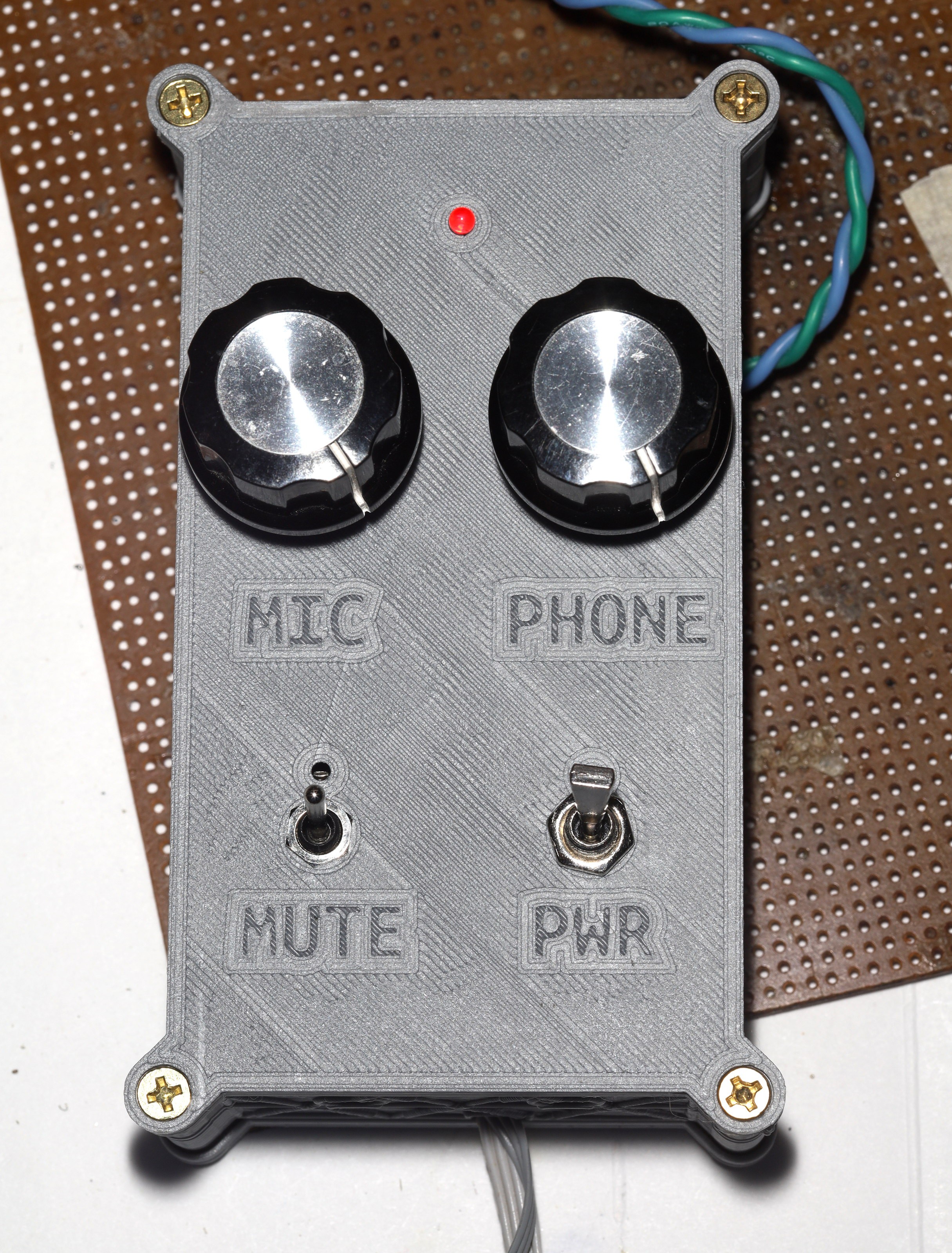
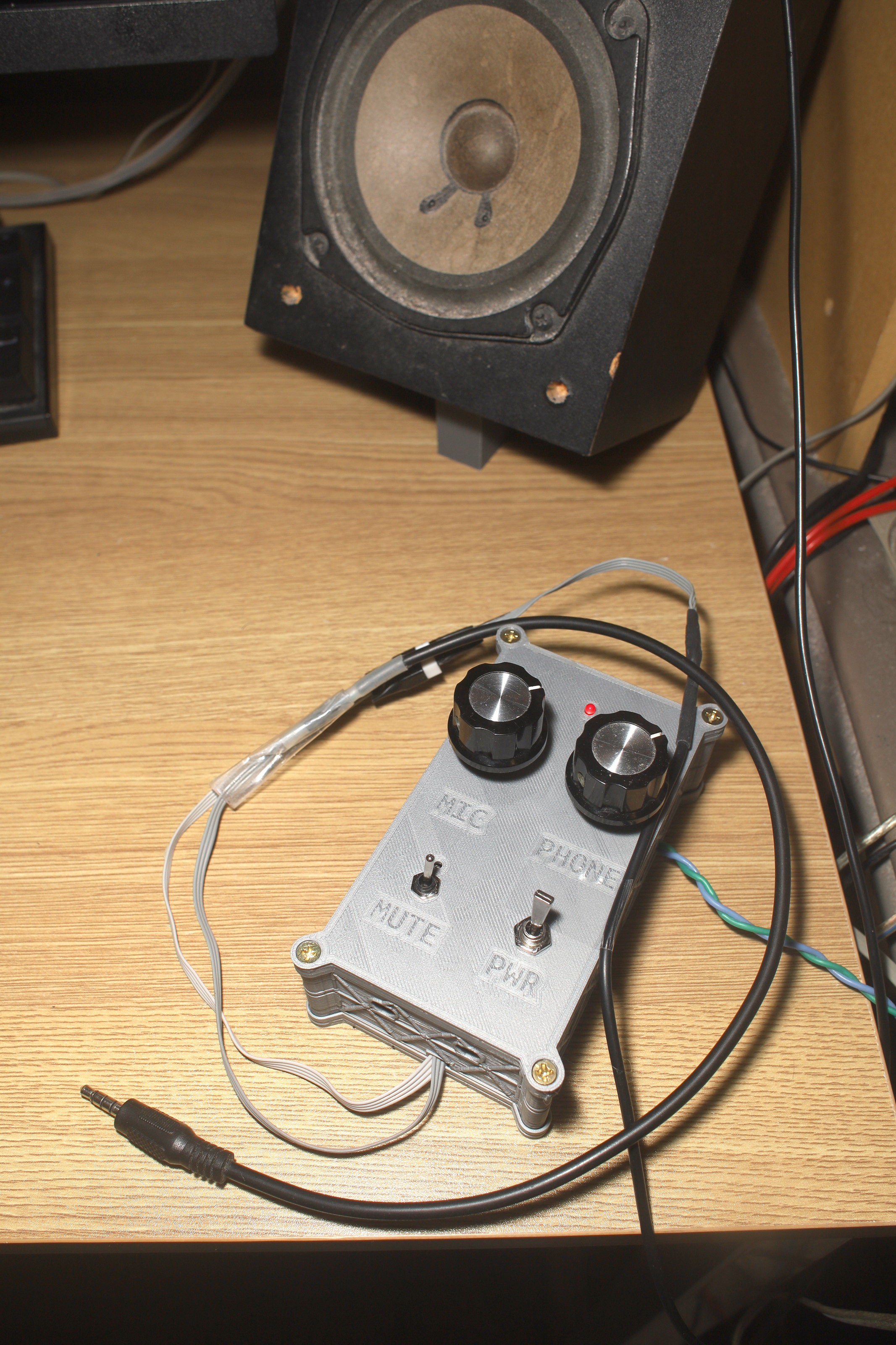
Because the Alphabet corporation doesn't allow us to have our phone screens on while making a call, it's very slow to toggle the software mute button. The lion kingdom finally added a mute switch to the headset mic out.
Using a switch to disconnect the microphone didn't work because RF just entered the floating wire. Turning off the phantom power didn't work because the microphone still detected sound without power. Turning off the voltage follower didn't work because current still flowed through the op-amp without power. Directly grounding the microphone made too much of a pop, but muted it.
Only a transistor turned on by an RC circuit could ground it without too much of a pop. There always must be a pop, since the microphone turns on at a threshold voltage instead of gradually getting louder. Only an NPN transistor would work, since it has to pull the voltage to 0.
The mane problem is the speaker gets louder when the microphone is muted. Not sure why this is.
The original design regulated 12V down to 5V for phantom power. Having 5V later proved useful for muting the microphone & powering an LED.
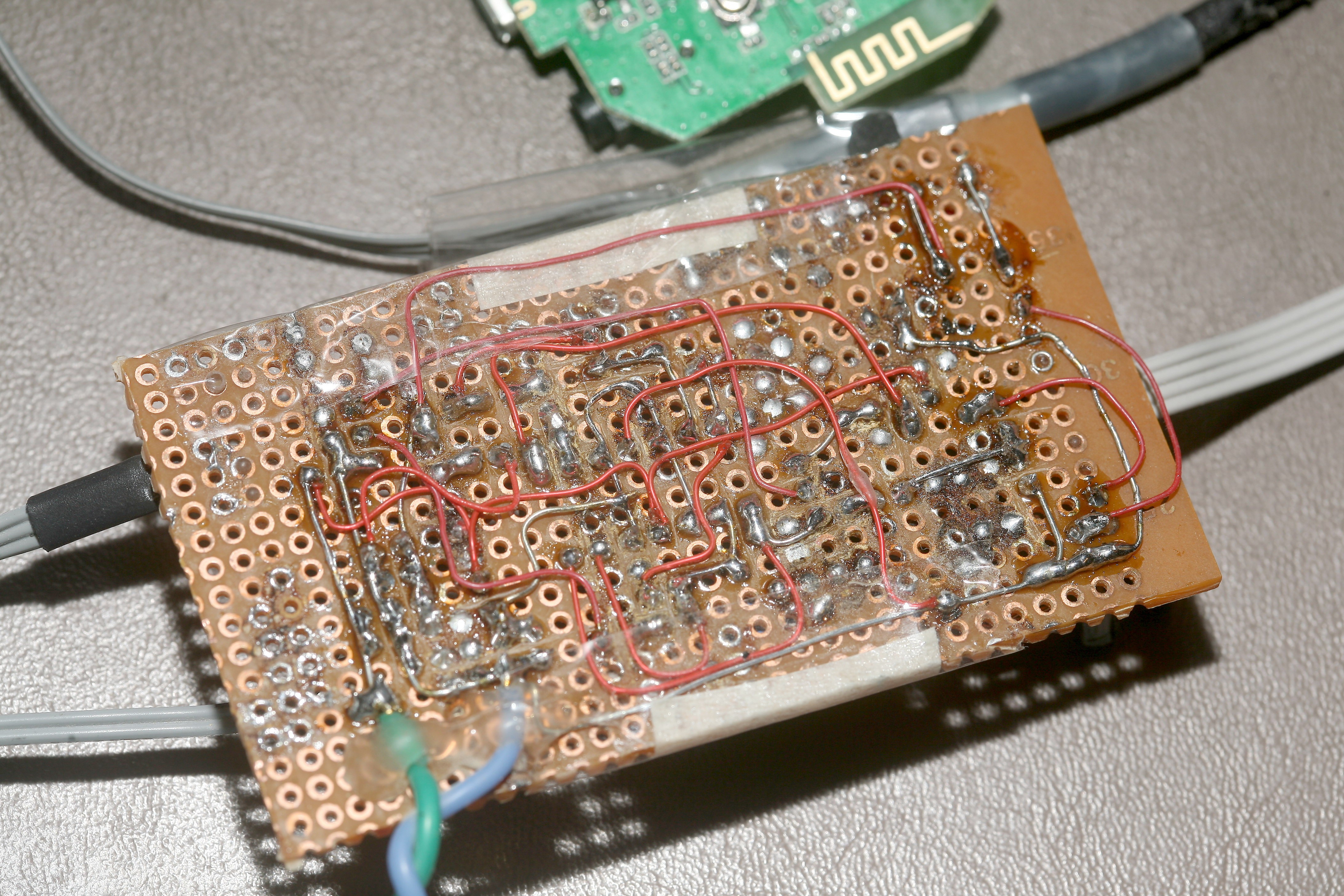
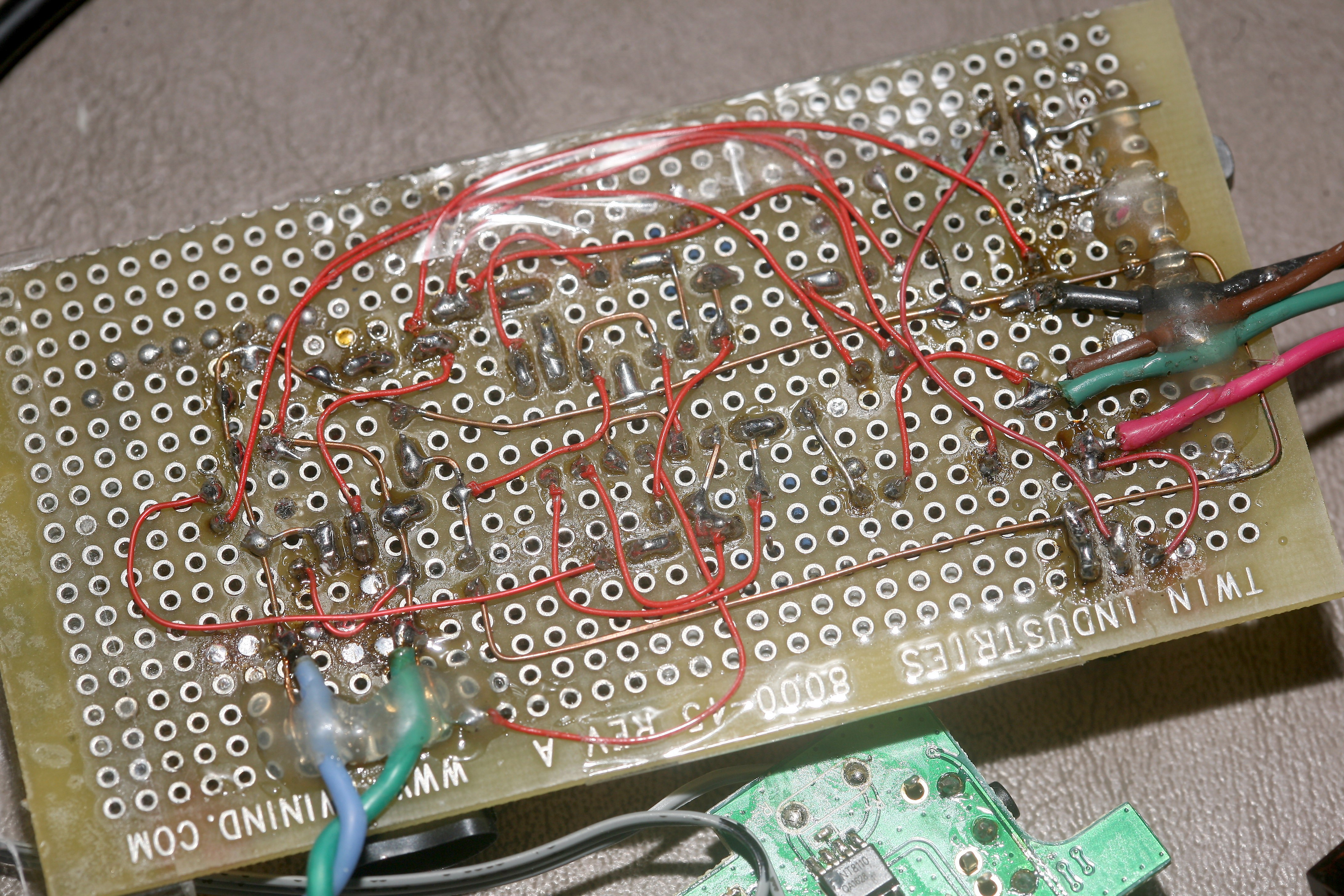
The original had 2 op-amps shorted to power both speakers in parallel. It could have used 1 op-amp for each speaker, but it would have required separate pots for each speaker.
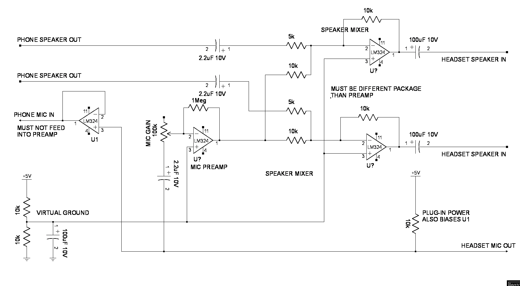
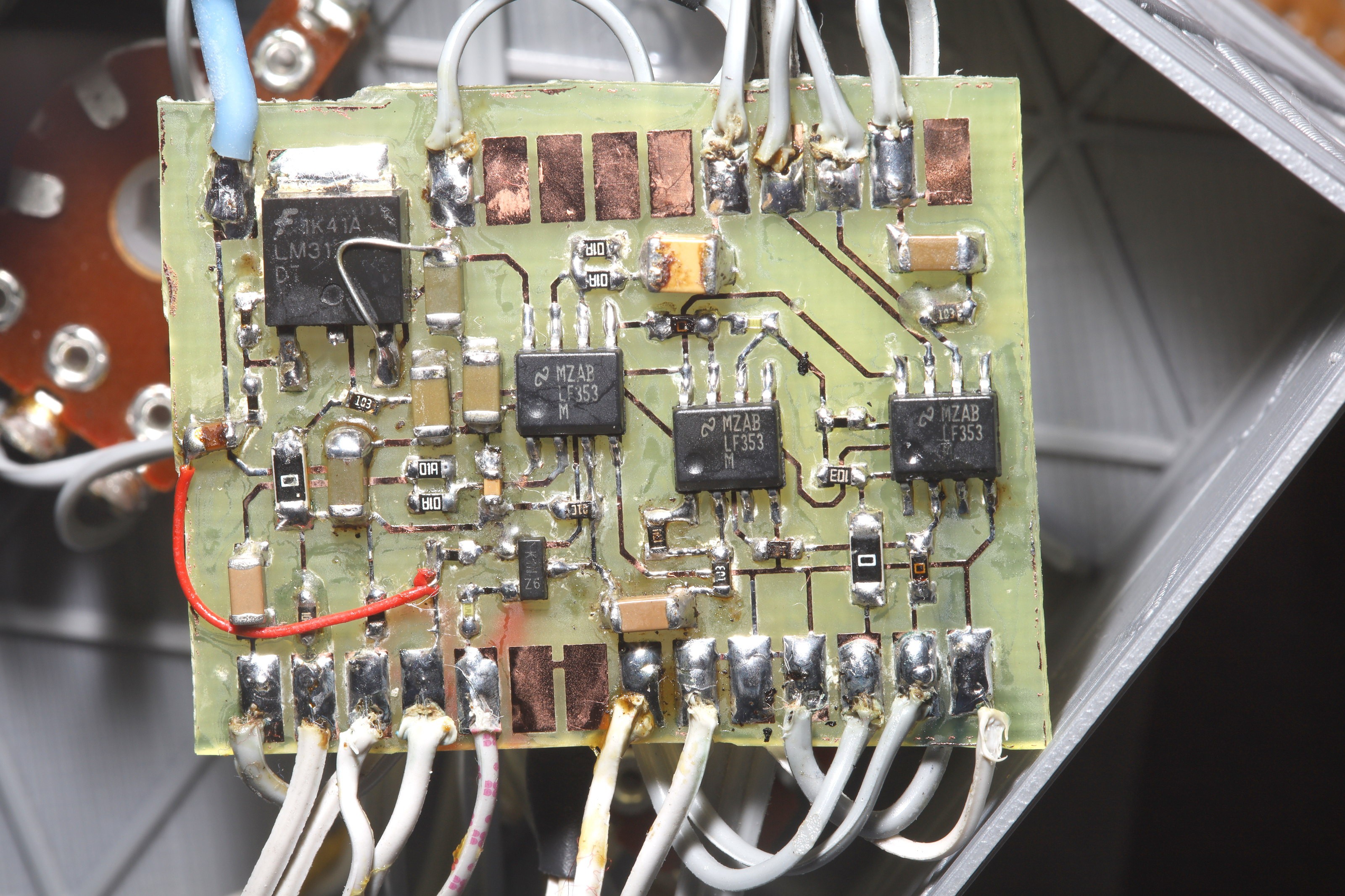
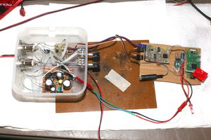
The original circuit was rebuilt twice, over the years, using surface mount & higher efficiency AD8604 op-amps. The rebuilds left out the inductor & had stereo sound. They had fixed gain for the speakers & mixed the same microphone signal into both speakers, after the preamp.
These redesigns proved fatally flawed. The AD8604's needed a 10R on the speaker output to stop oscillating. Newer phones, despite not using GSM, still produced interference which required the inductor. The higher efficiency AD8604's had serious feedback & crosstalk problems the LM324 didn't have. They might be intended for digital amplification rather than audio amplifiers.
The original design ganged 2 op amps to drive the speakers in mono. The new designs drove the speakers with 2 op amps in stereo. The original design used cascaded 10x amplifiers for the mic preamp. The new designs used a single 100x amplifier for the preamp. As in the original design, a voltage...
Read more » lion mclionhead
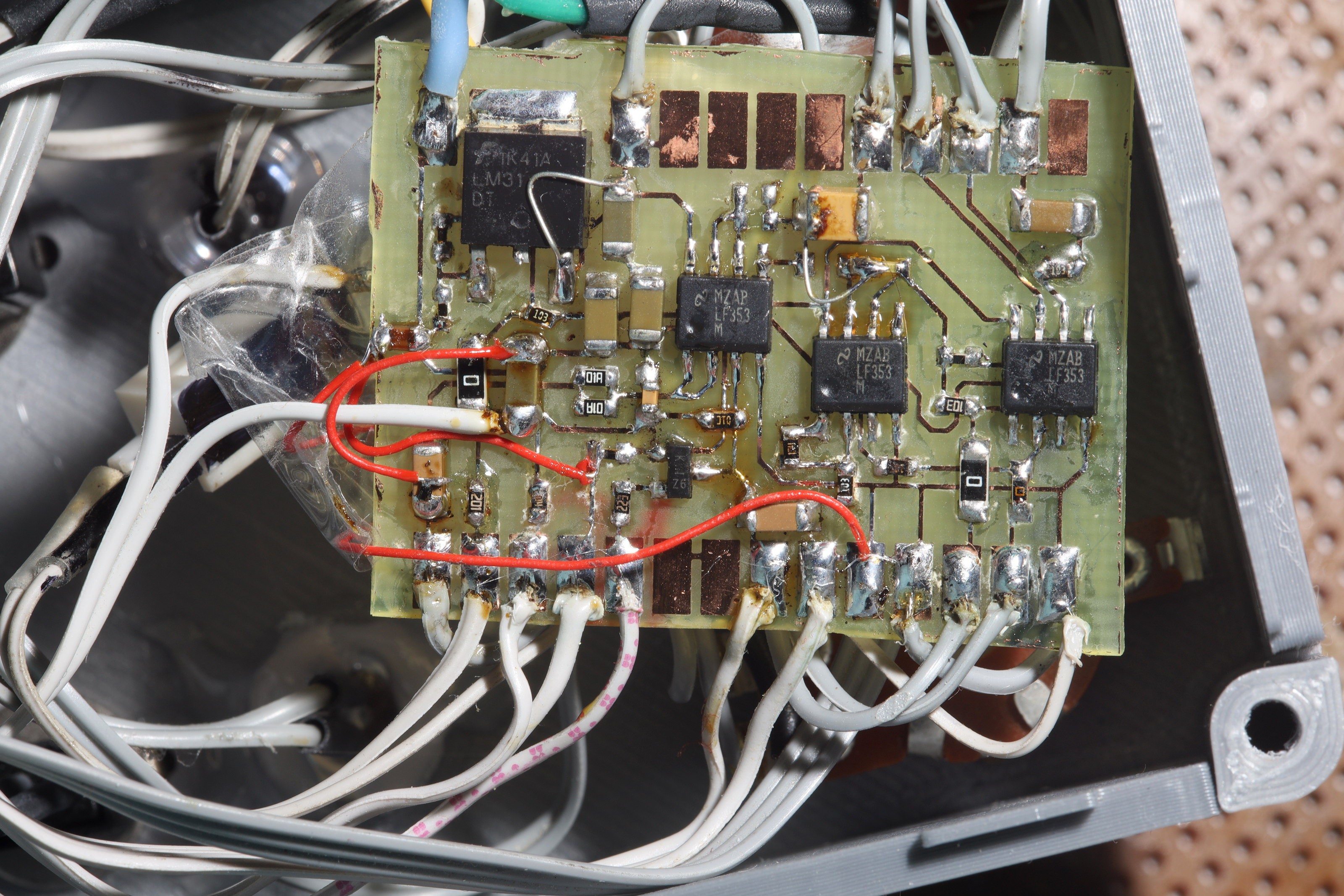
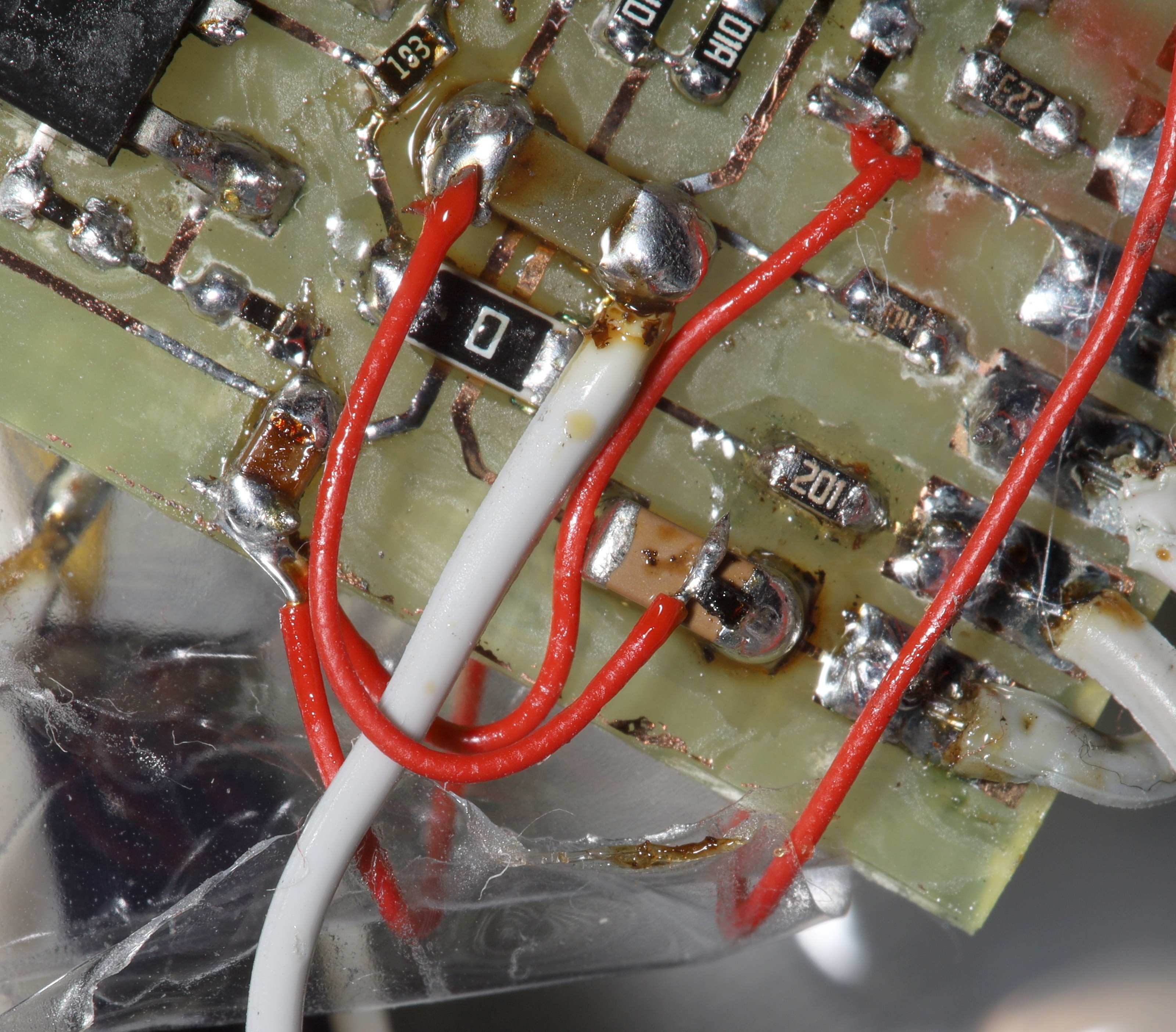
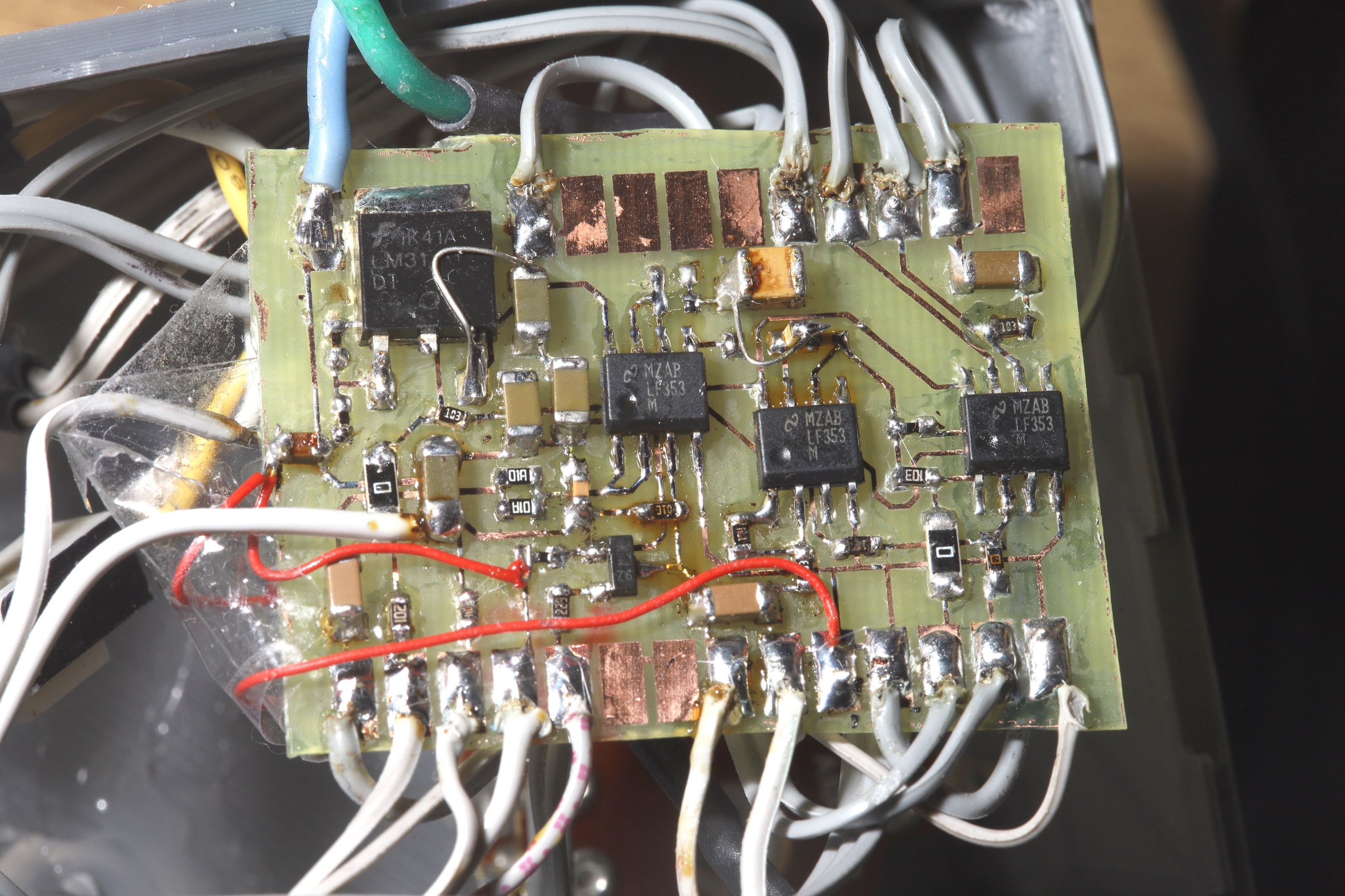
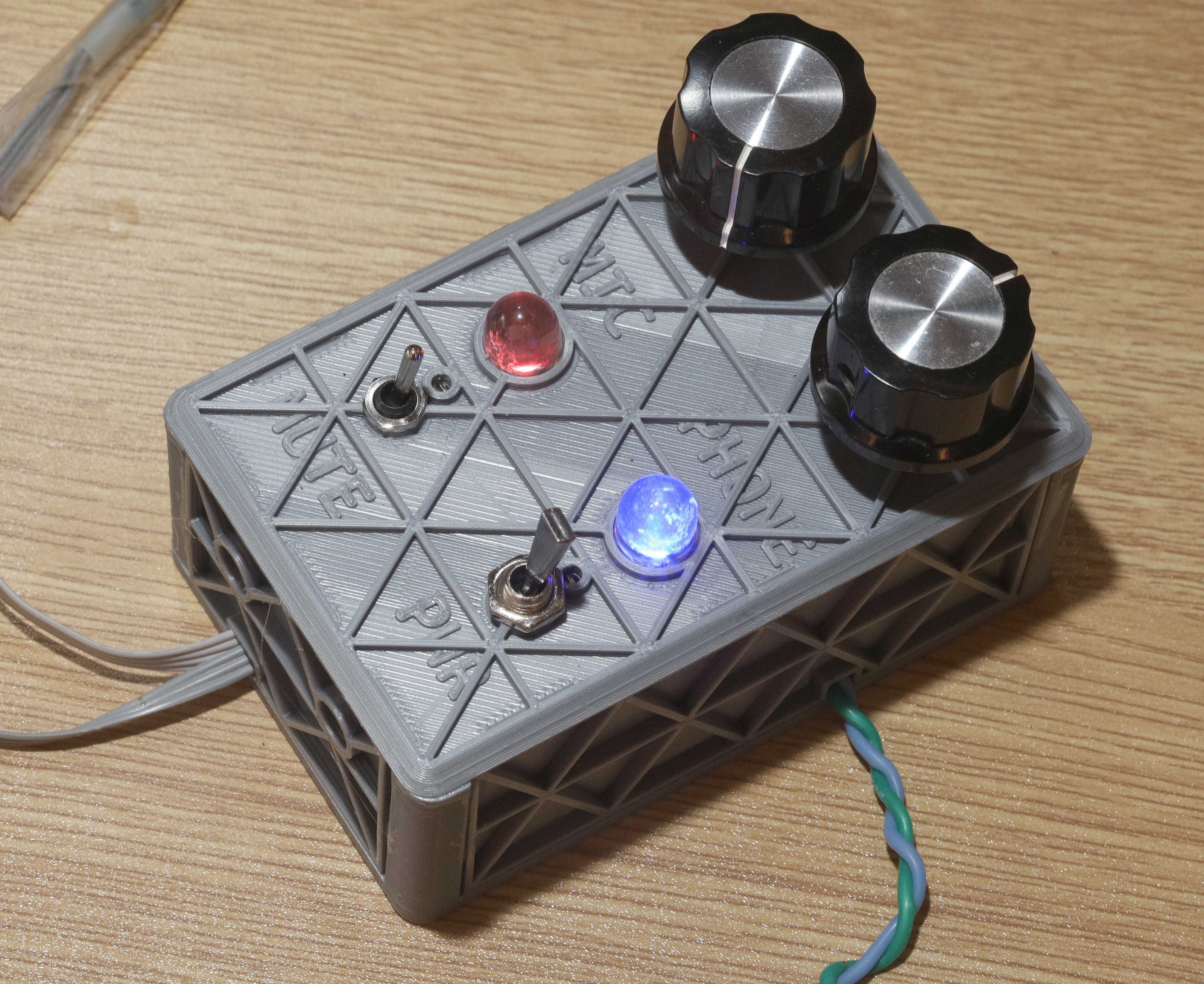
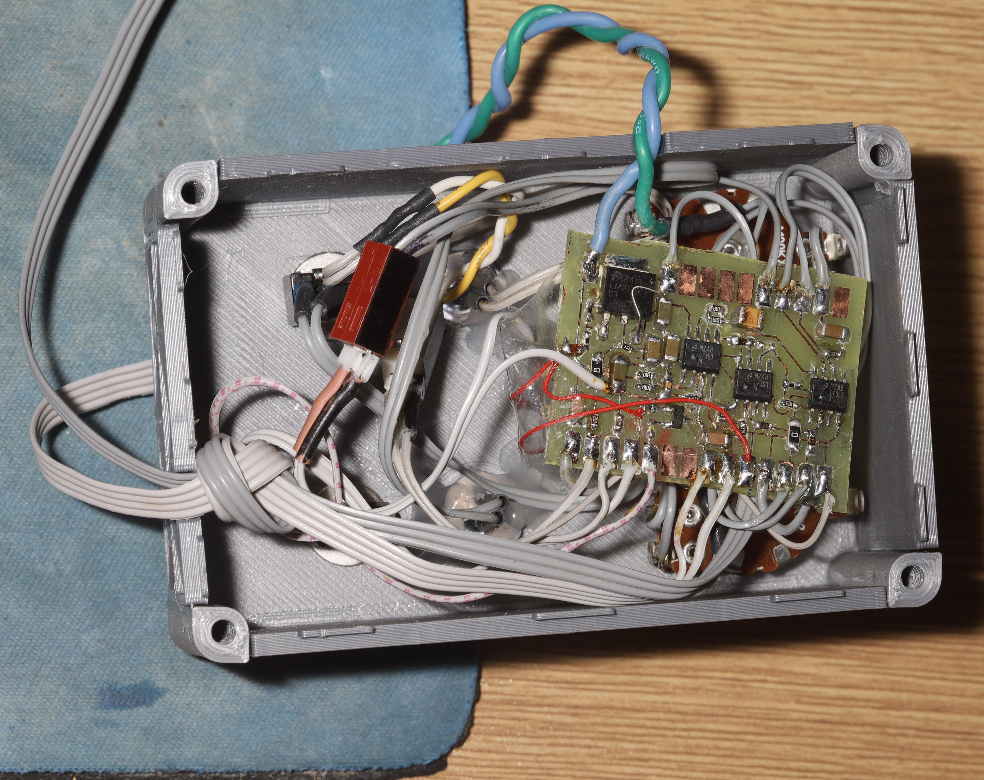

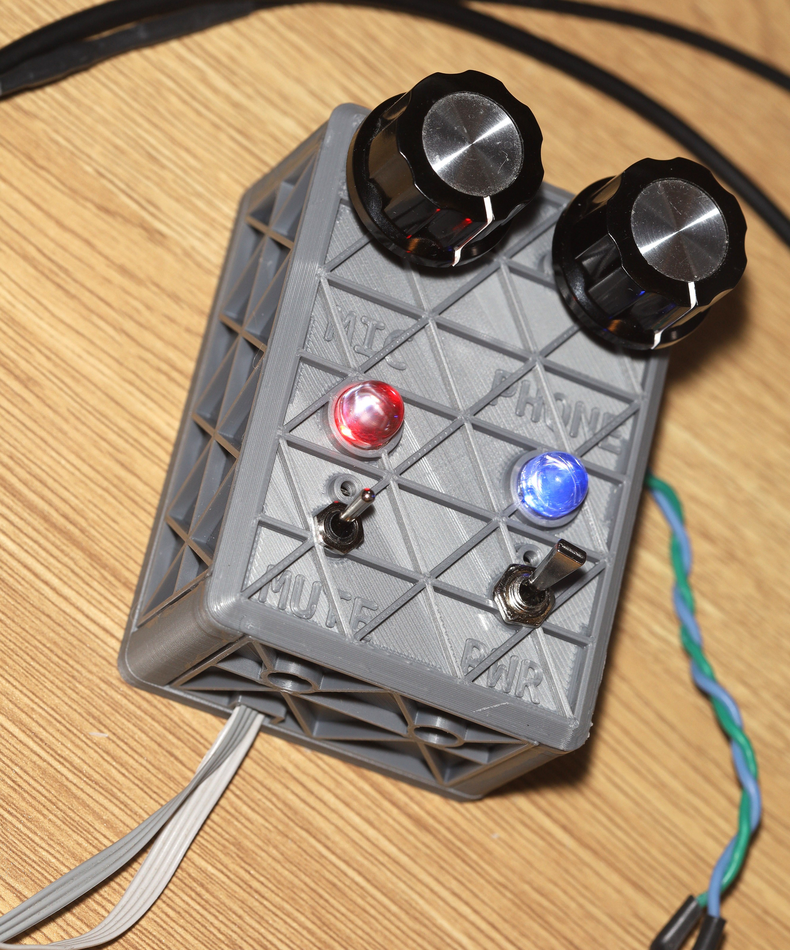
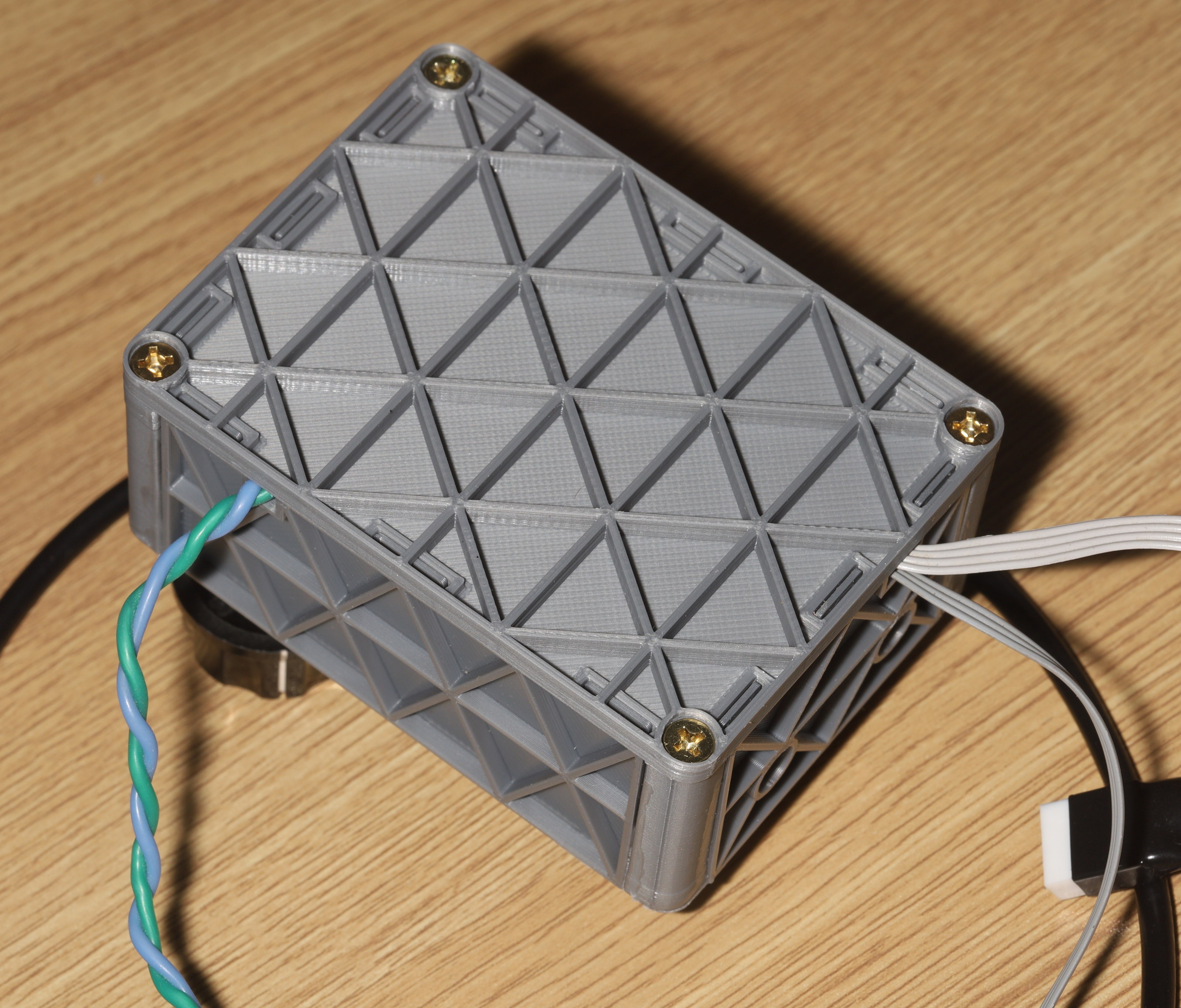
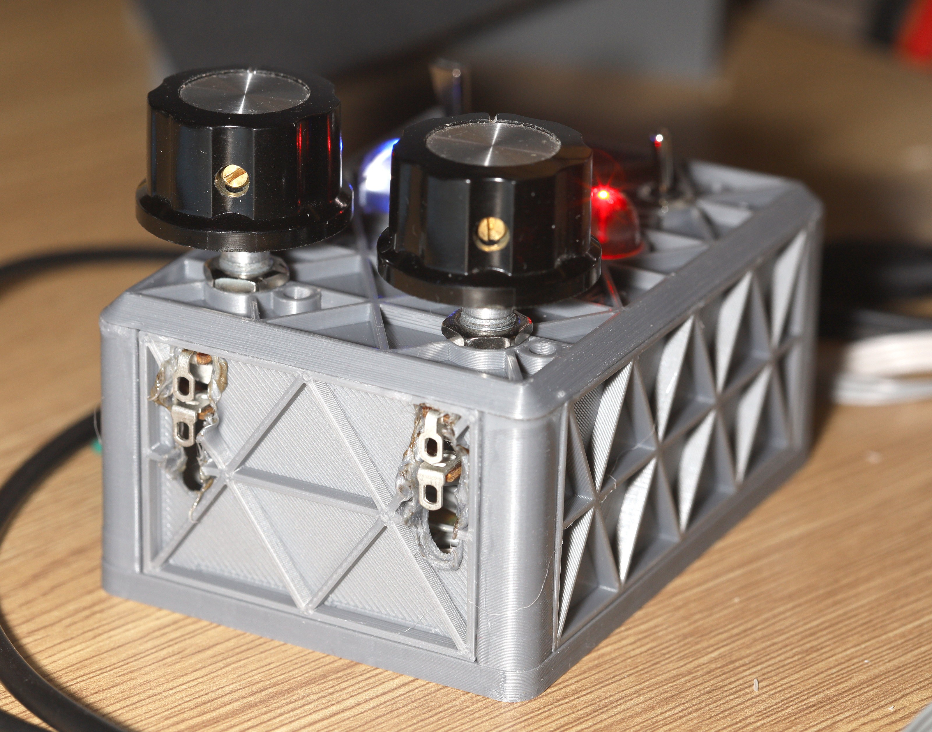
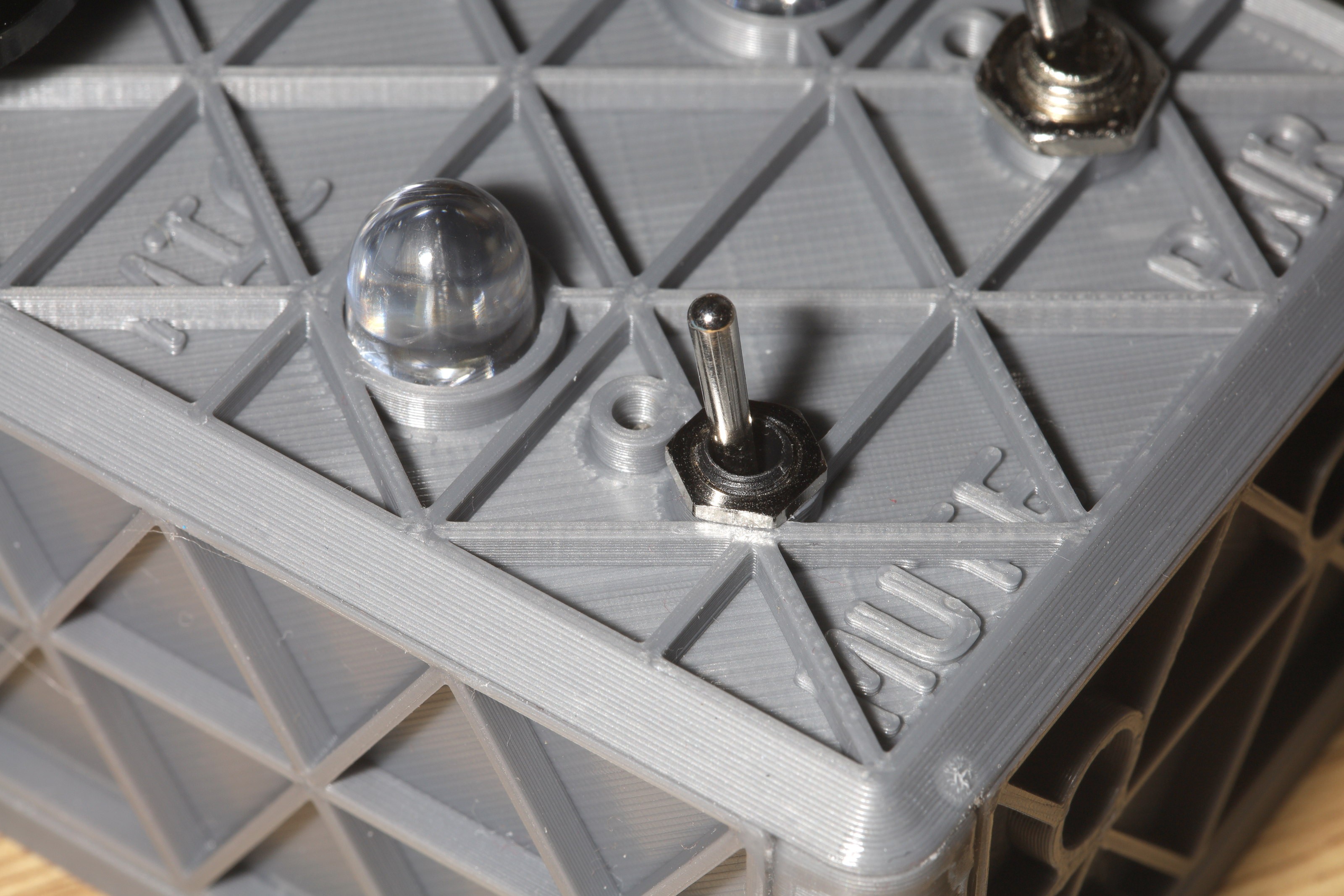
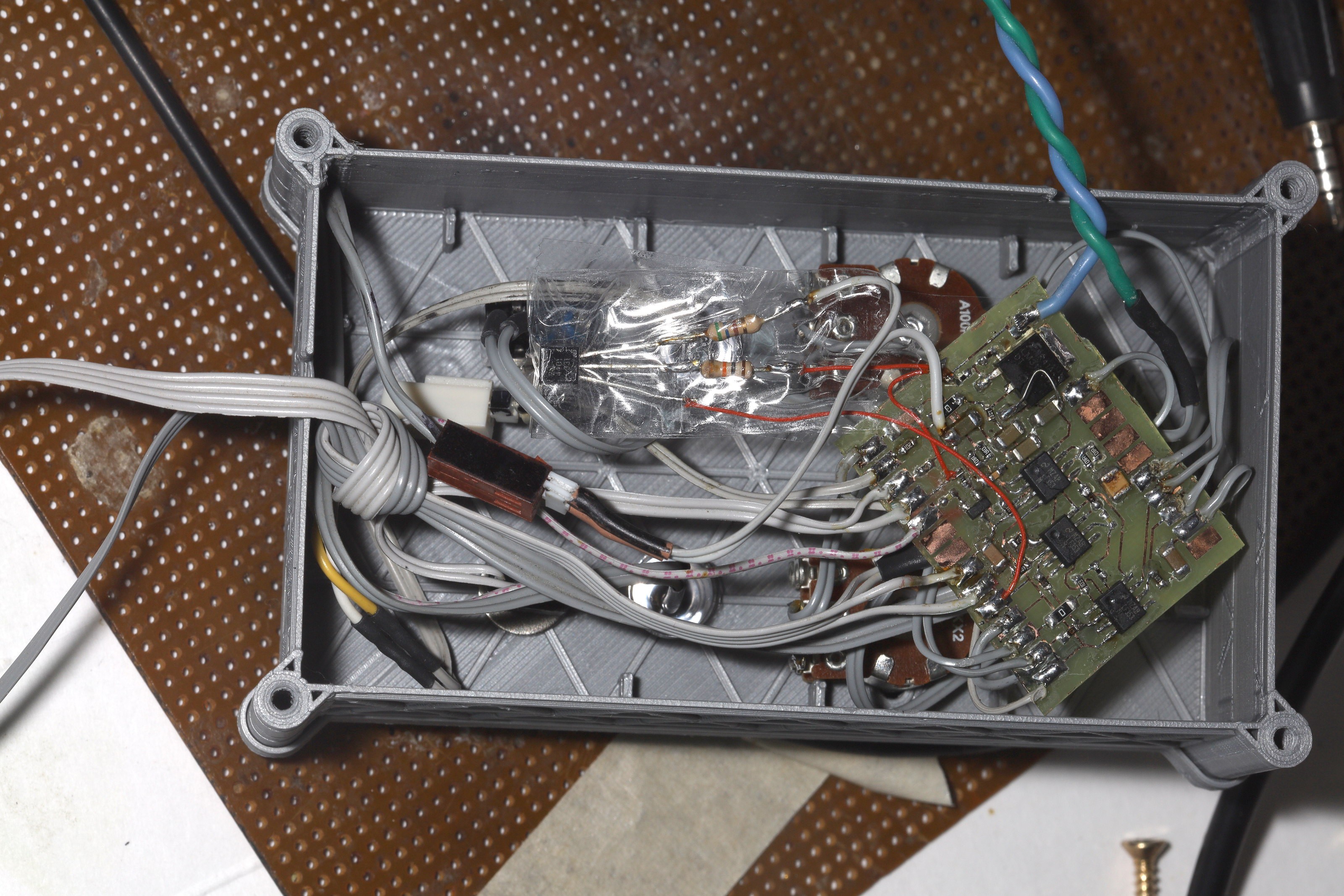
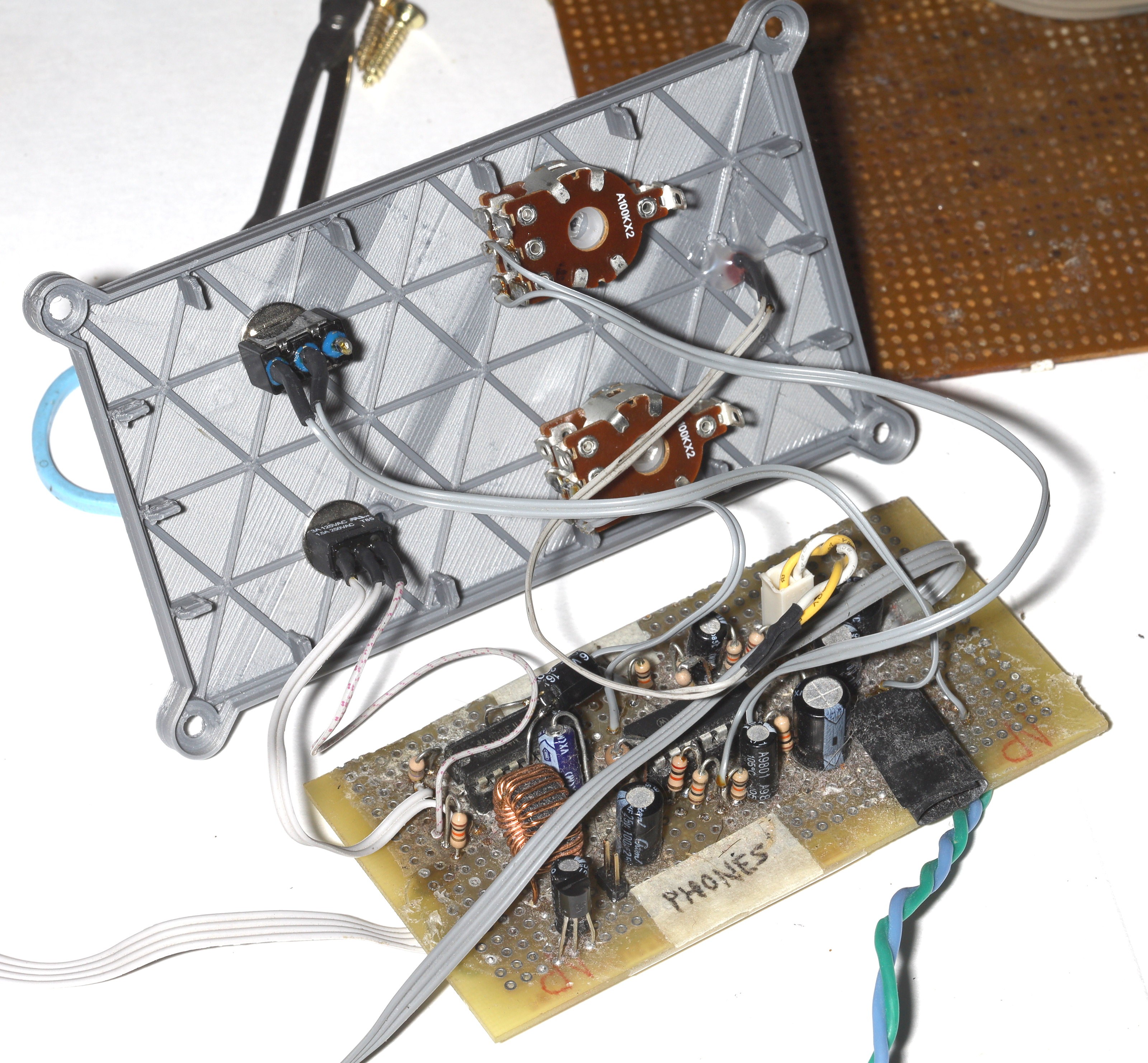
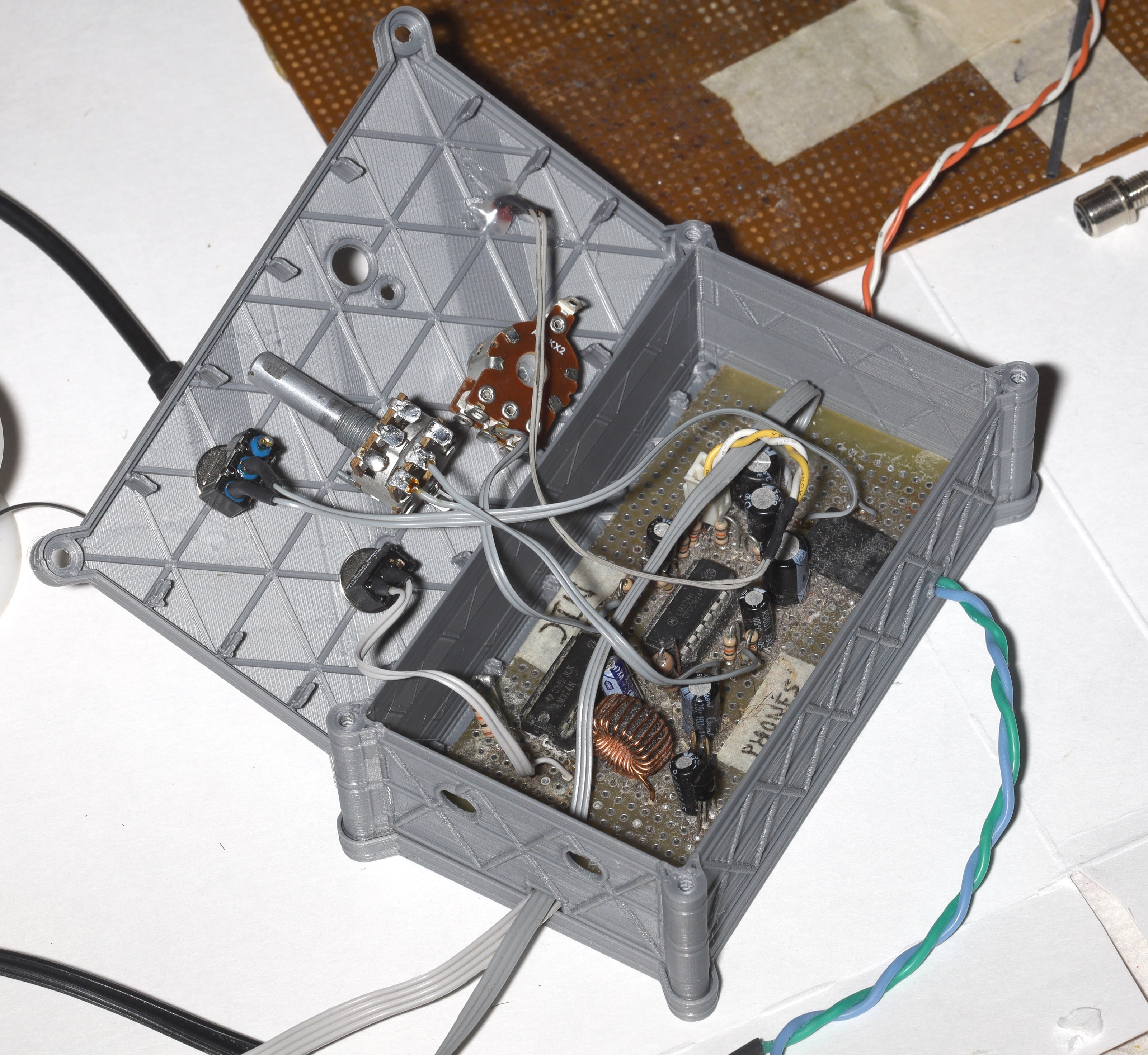
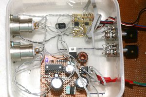
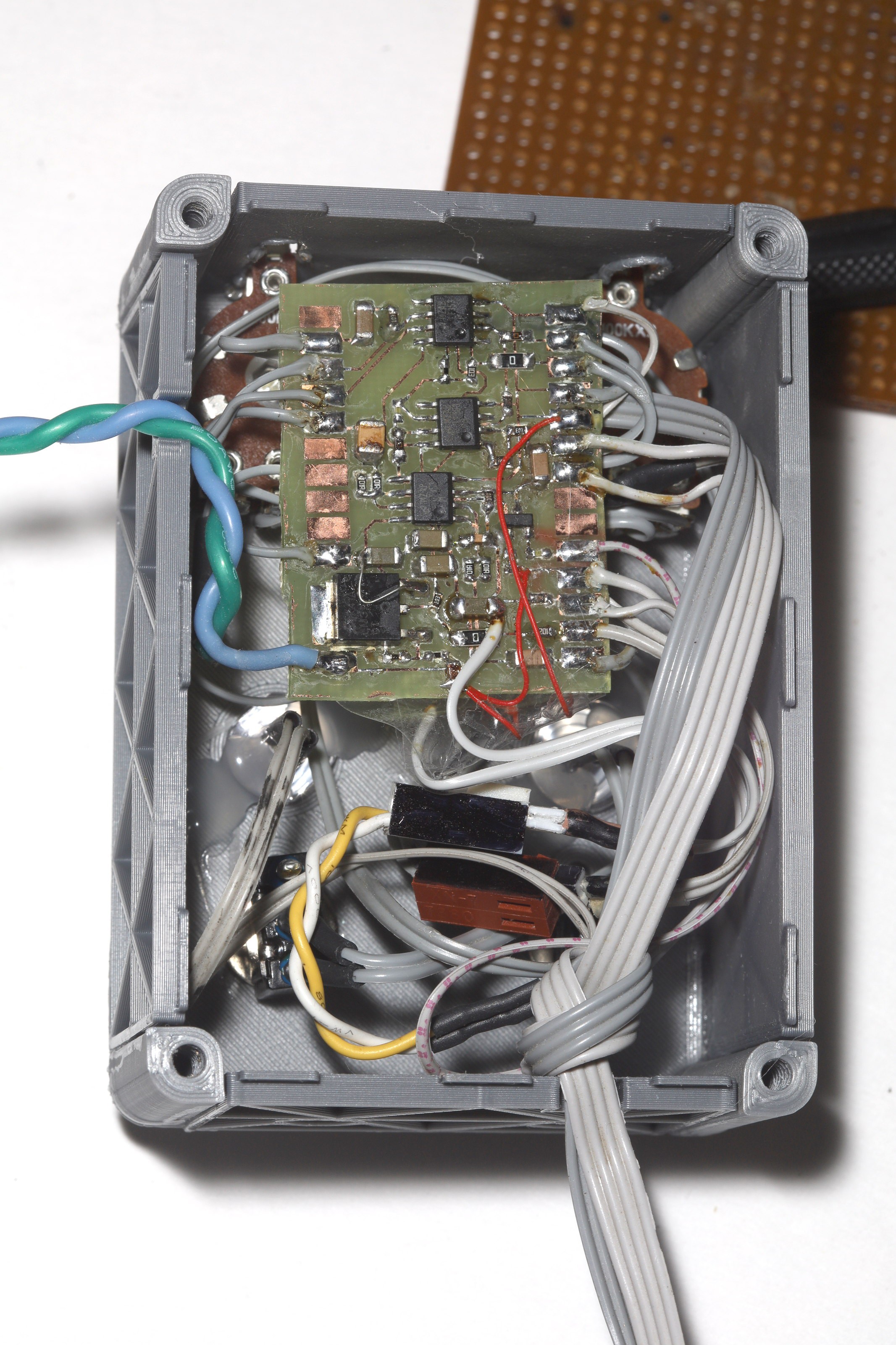 The enclosure height is just enough to fit all the wires in without kinking. A 100k turns the mute on & a 10k turns the mute off, hence why turning off is faster.





 Justin Scott
Useful. Hardware monitoring without lag. Like it.
Schematics are very nice, I can reuse it at home to make intercom between rooms.