Close
0%
0%

Ultimate stereo amplifier

Building a home hifi component from scratch was a very early dream. There was finally an excuse to do it.

Similar projects worth following
In August 2016, the 16 year old, bulky Yamaha HTR-5230 was dying. It took $16,000 of real estate. It ground looped randomly, put out a flamethrower of heat, & didn't have a working volume control for the several years. The Yamaha was the pinnacle of amplifiers, at $400 in 2001 dollars. Its Dolby pro logic, effects, & subwoofer brought true memories, even if it sounded flat. The center speaker amplifier soon stopped working. The space for 5 speakers ran out. It became clear the lion kingdom would never afford a space suitable for using the subwoofer. By 2010, it was down to 2 speakers & never used for anything but amplification.


It had been nearly 20 years of buying cheap commercial amplifiers or hacking things together, just to get good enough audio from the PC to not require a separate home theater. They all died quickly. Building a hi fi component from scratch was no longer a dream but a practical solution.

8/20/2016

The amplifier section

The decision after decades of planning to make something custom out of old MOSFETS, reading comments on the DROK, & a brief dreams of tubes, was to invest in a bog standard STA540 from $parkfun. It would also be the most compact.

8/27/2016

Reworking the HTR-5230 begins
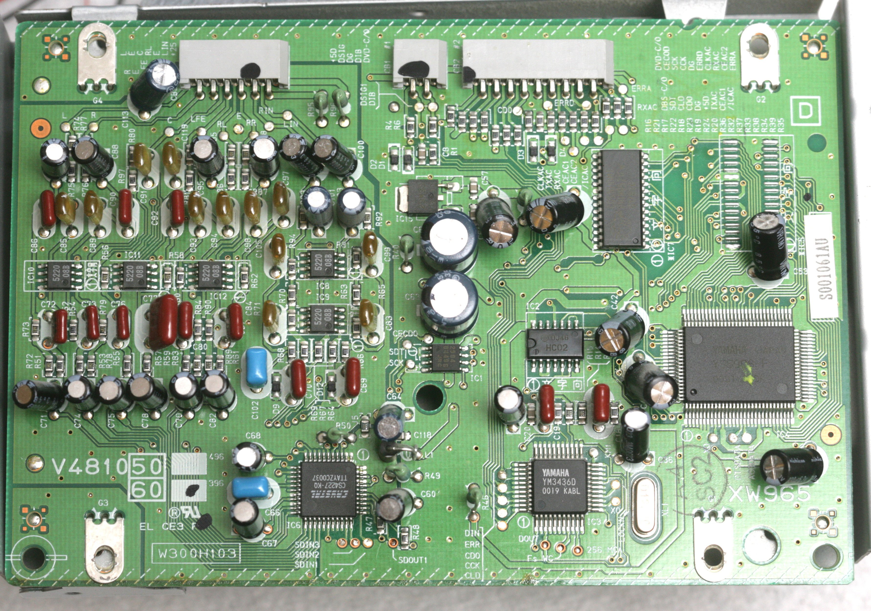
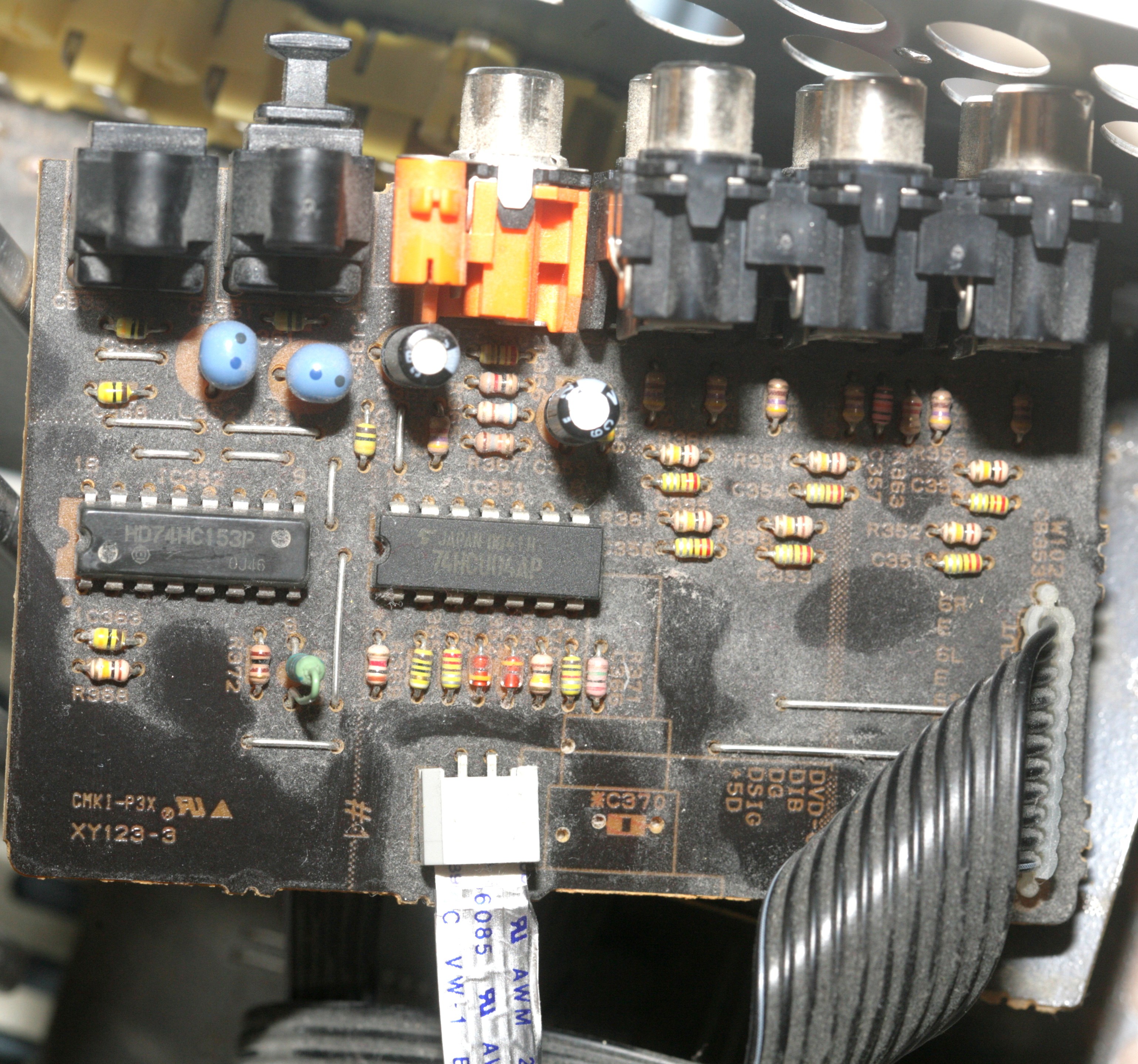
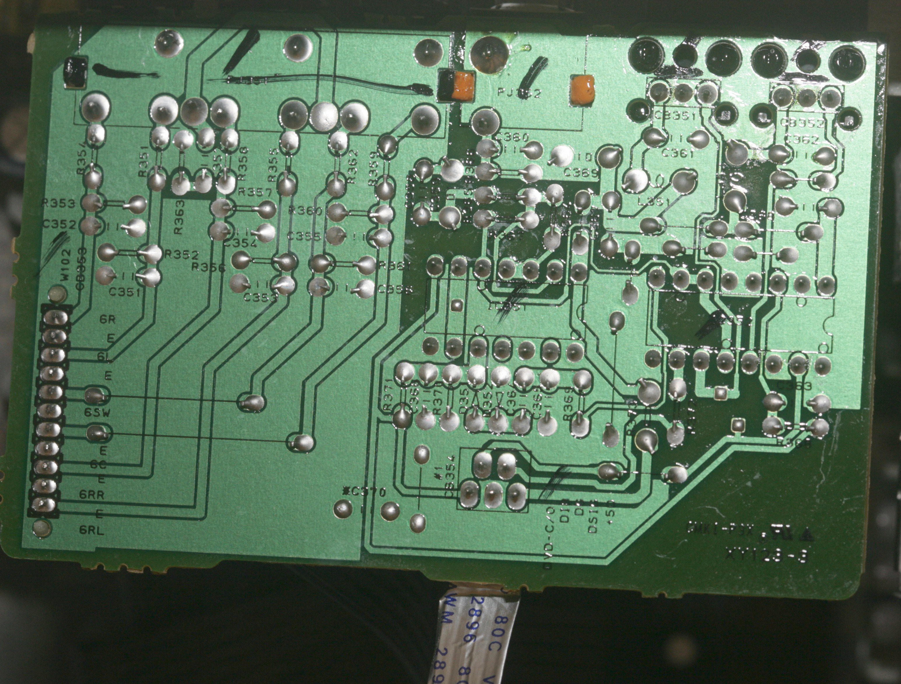
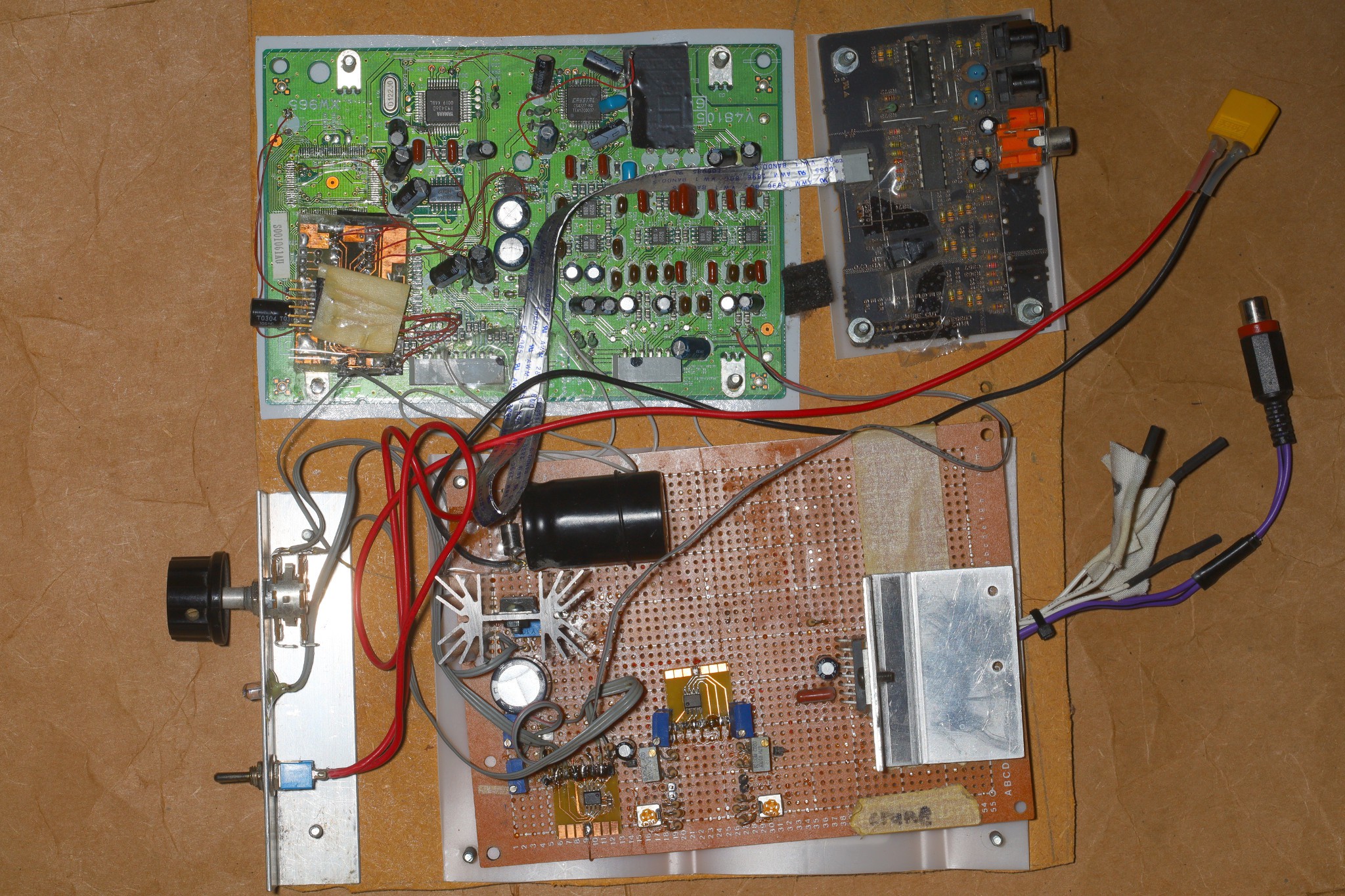
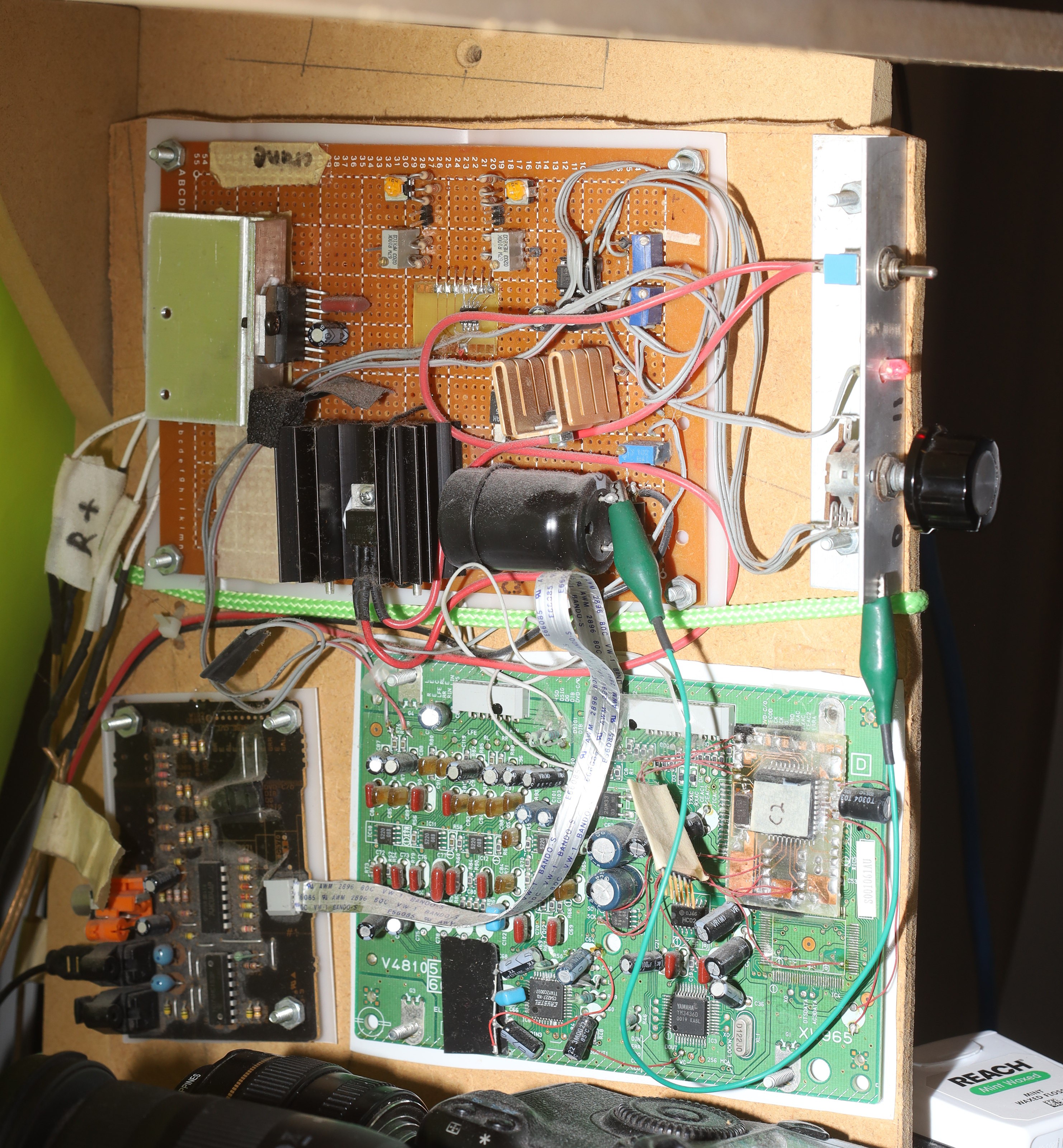
Analog input proved too noisy. Reviewing the available datasheets for the HTR-5230 revealed the TOSLINK input could be extracted from it for use in another amplifier. The dual TOSLINK inputs were multiplexed into a single input by a simple voltage level. The single input went into the 1988 era YM3436 which converted it to I2S. This was configured by simple mode select pins. 

The I2S went into the 1999 era CS4227 which had the DAC. The I2S was routed through the undocumented YSS908 to process the special effects. It could easily be hotwired to bypass the YSS908. 

Everything uses 5V at a fairly high current. The CS4227 is configured for SPI. You can see data on the AD1/CDIN line when changing inputs. CDOUT isn't connected. CCLK goes at 100khz & sends 2 bytes when changing inputs. CS is erratic.

The initialization merely sets the attenuation registers. Their default is 127

reg value
4 -> 5
5 -> 5
6 -> 13
7 -> 13
8 -> 13
9 -> 23

The analog out after attenuation is 1.8V-2.8V. It goes to a butterworth filter recommended in the datasheet, but requiring +/- 25V. The butterworth filter needs a fairly high current & generates a lot of heat. The final output is -3.3 - 3.3V. The filter GND needs to be raised for it to have a chance.

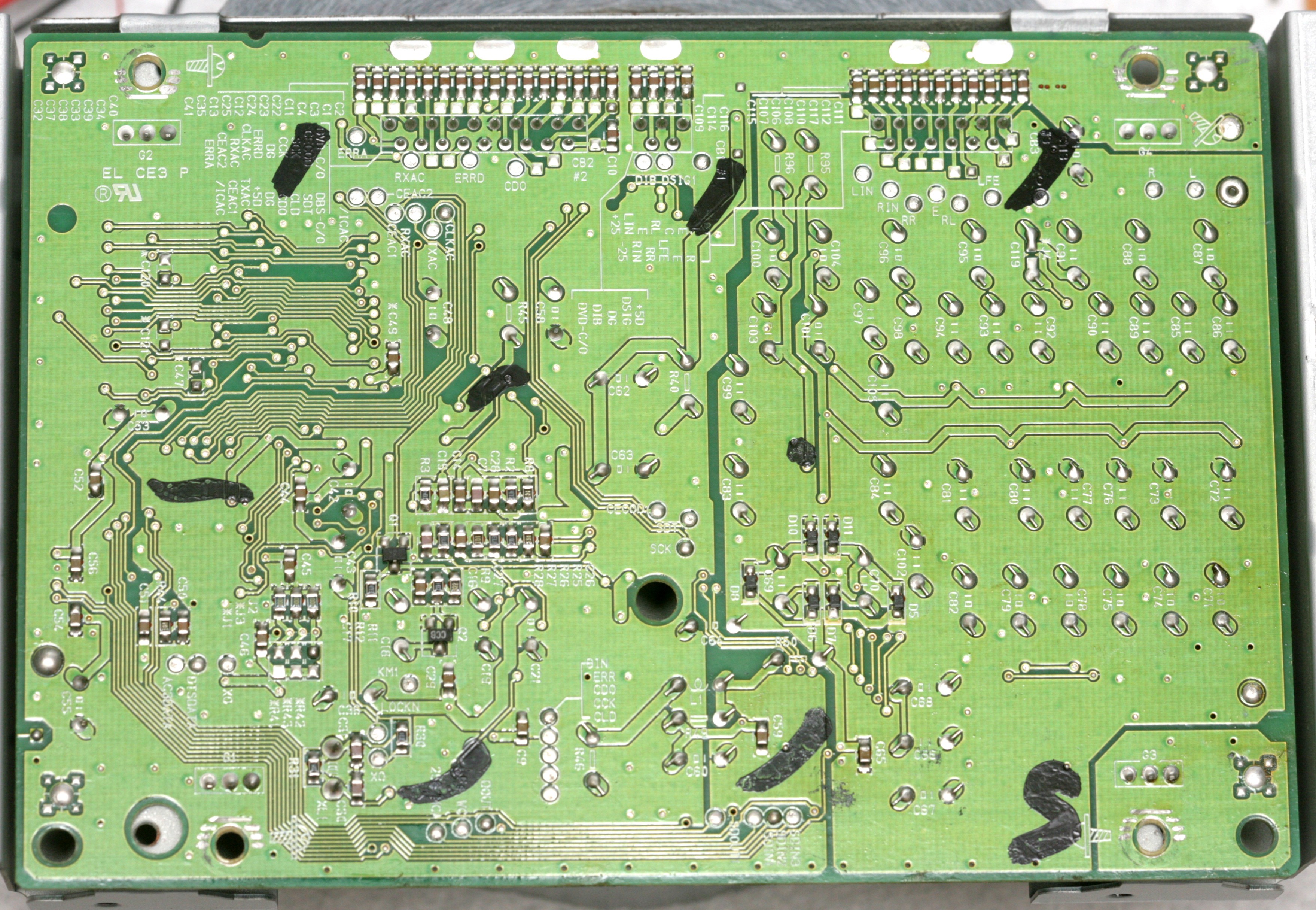
The filter ground fortunately had very few connections. The 1st step was disconnecting the filter ground from the logic ground, which required lifting a few caps & cutting a few traces, but it was perfectly happy. 

The next step is reversing the direction & removing some caps before raising filter GND to 5V. Also very important to look for any other parts which might explode.


9/4/2016

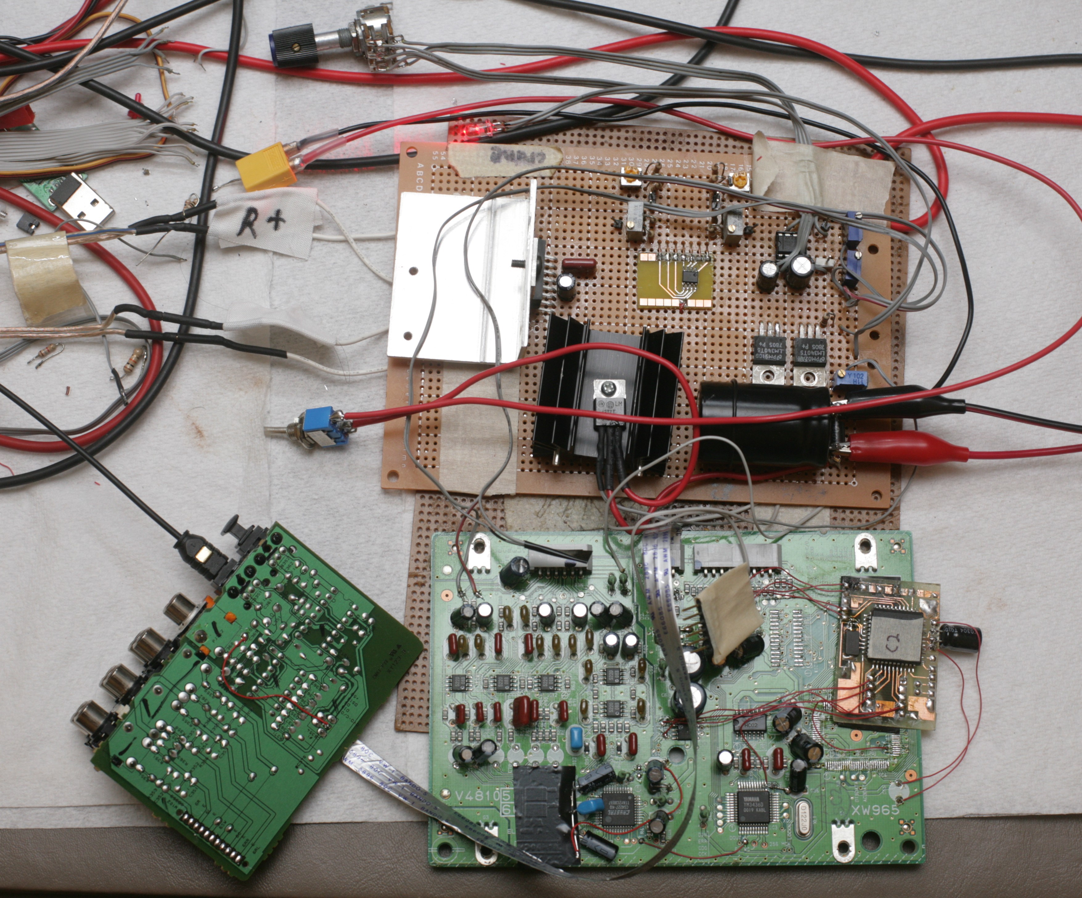
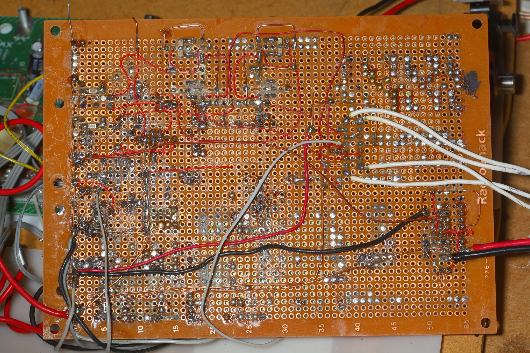
It came together manely as expected. The mane difficulty was getting the STA540 to work. For the STBY pin, the datasheet says MAX V for play is 1.5V, MIN V for standby is 3.5V. In reality, STBY needs to be pulled up for play & grounded for standby. Trap for young players.

The CS4227 needed a substitute microcontroller to initialize it, as expected. Quite a few more registers had to be set in a certain order to initialize it, which weren't sniffed by the oscilloscope. The YM3436 needed a few pins biased, as expected. Traces had to be cut. The mane challenge was both chips needed reset to be low for a certain time after powering up. The YM3436 wouldn't initialize if reset started out high.

The complete DAC took a lot of power. The +25V rail wouldn't initialize when connected to the 10V regulator. The 10V came from a 5V regulator with a 5V virtual ground, but the +25V rail started below 5V. The regulator seemed to detect the +25V rail starting below its virtual ground of 5V & shut down by some kind of SCR latchup. +25V ended up connected to the raw 12V. The 5V virtual ground initialized properly. 

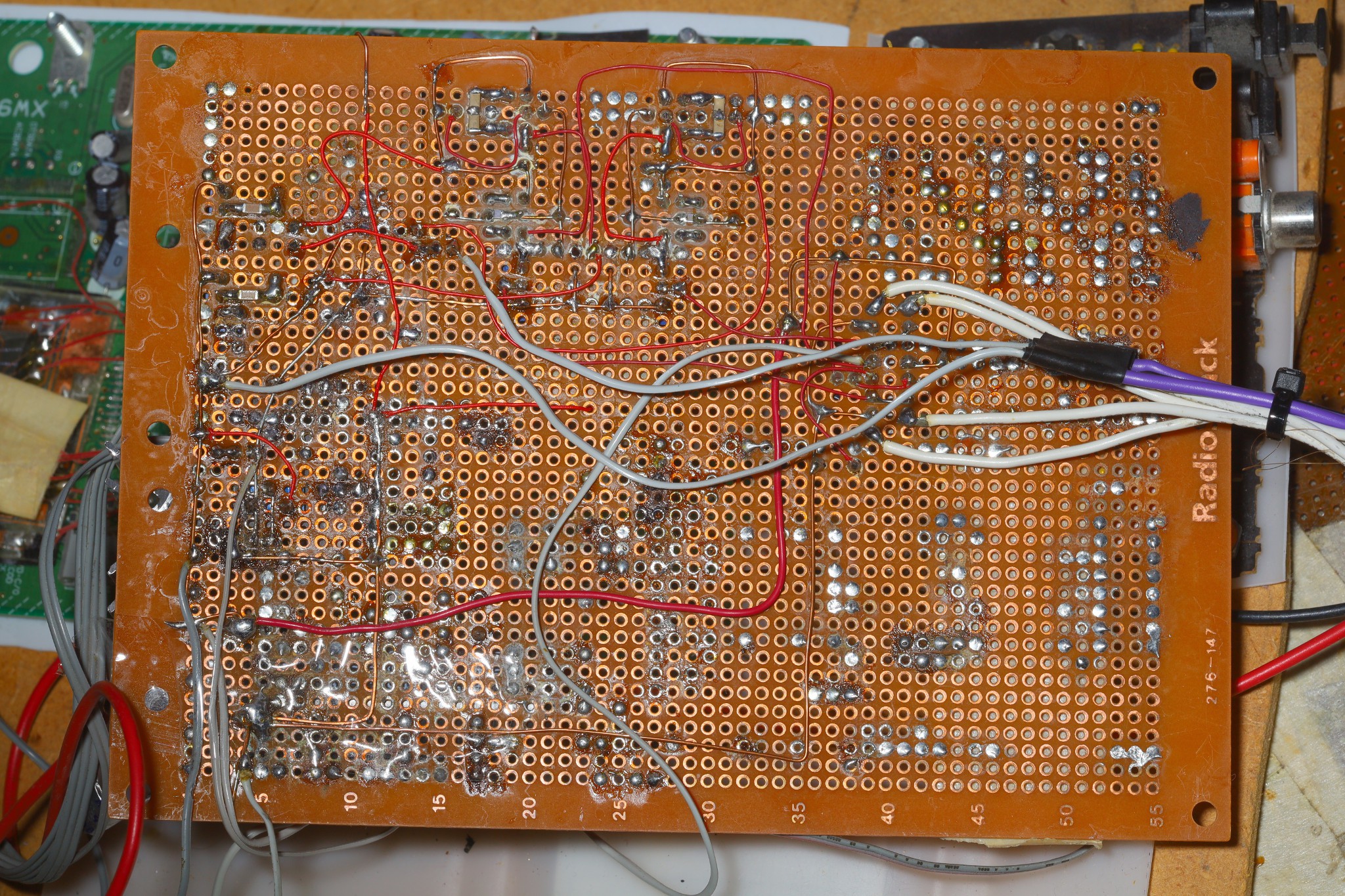
The total quiescent current with the power amplifier & DAC was an insane 0.35A. The 2 5V regulators got quite hot. The STA540 needed a large heatsink. The mane problem when playing sound was the DAC needed its ground connected directly to the ground on the STA540. Connecting it anywhere else on either the signal or power ground caused distortion. Connecting to either signal or power ground on the STA540 worked, so the DAC being a DAC went to the signal ground.

This circuit definitely made less 60Hz hum & noise than the HTR-5230. 

https://sound-au.com/dwopa2.htm#s7
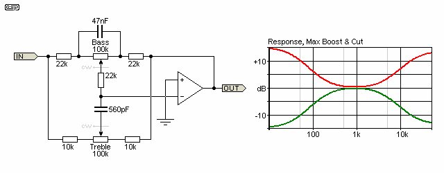
The Baxandall from Elliot sound projects worked much better than the EQ in the HTR-5230. Despite doubts, the decision was made to max out both treble & bass. Put in a single turn pot for the bass to make it easier, but left treble as a multiturn since it would never change.

The distortion experienced on 8/21 ended...

Read more »
cs4227_spi.s

Generate the SPI sequence to initialize the CS4227 from the Yamaha. Someone may find it useful, in another universe.

Assembler Source File - 3.87 kB - 12/28/2017 at 05:19

Download

pic_util.inc

inc - 26.79 kB - 12/28/2017 at 05:18

Download

  • Subwoofer teardown

    lion mclionhead09/01/2026 at 22:50 0 comments

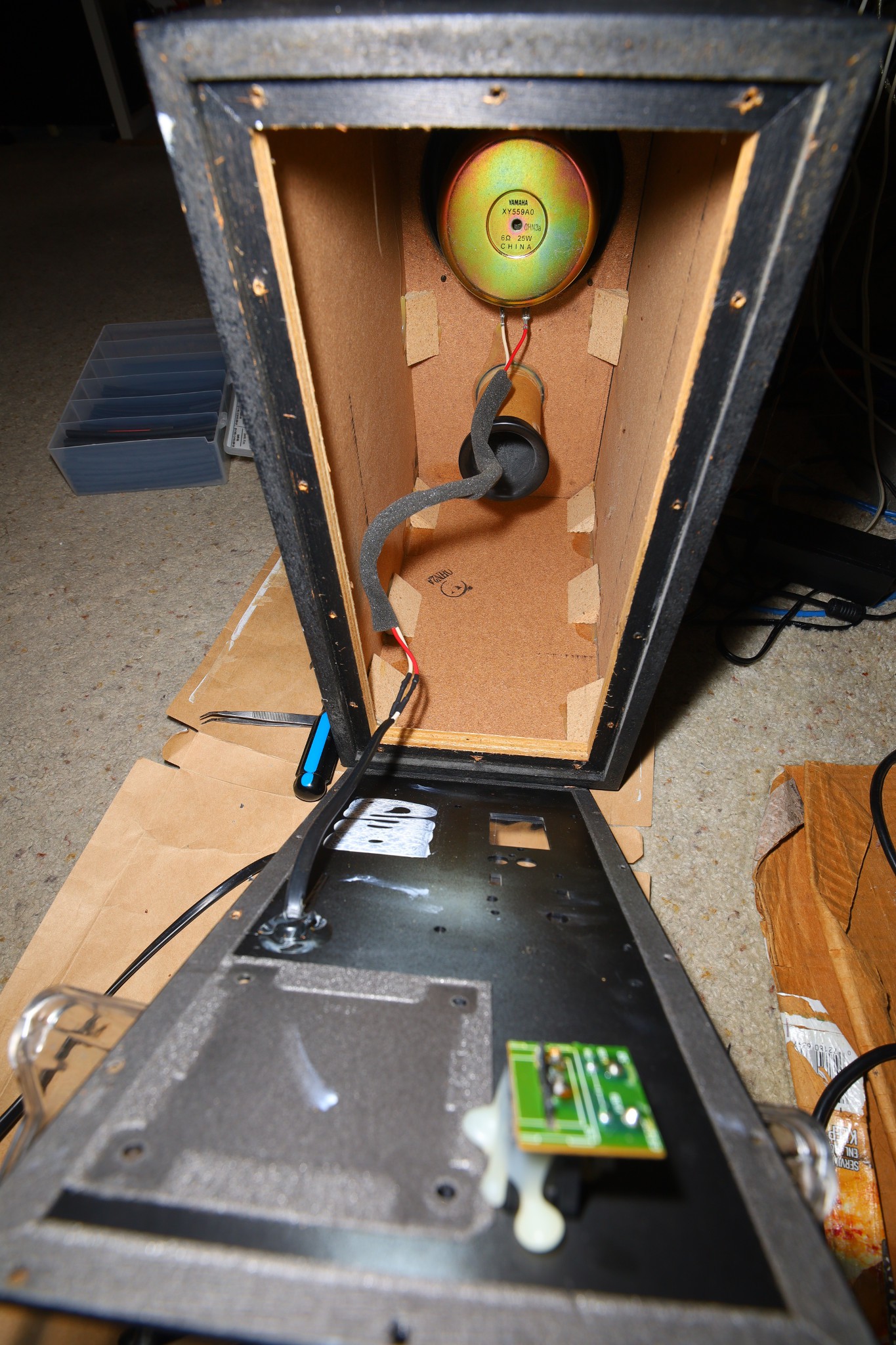
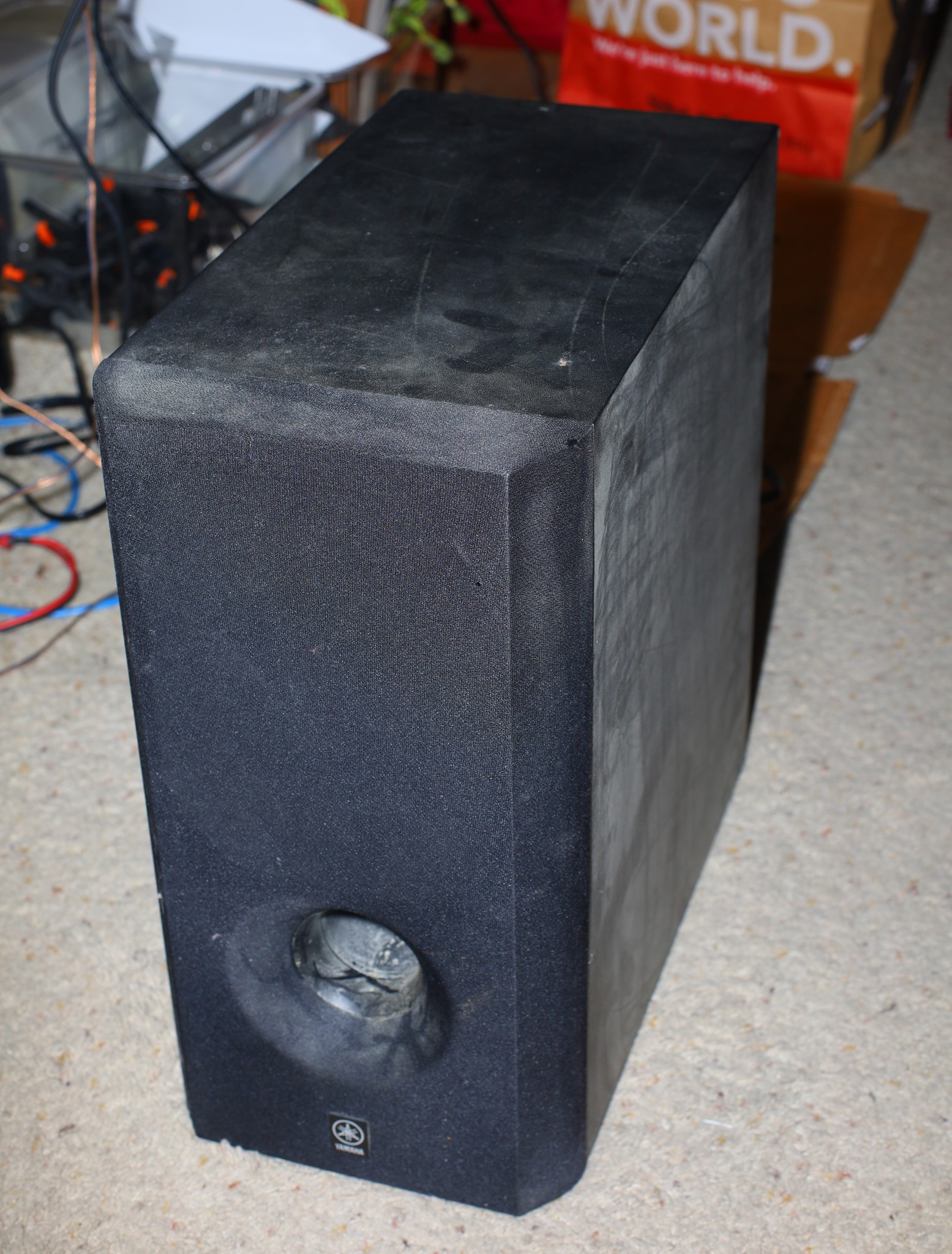
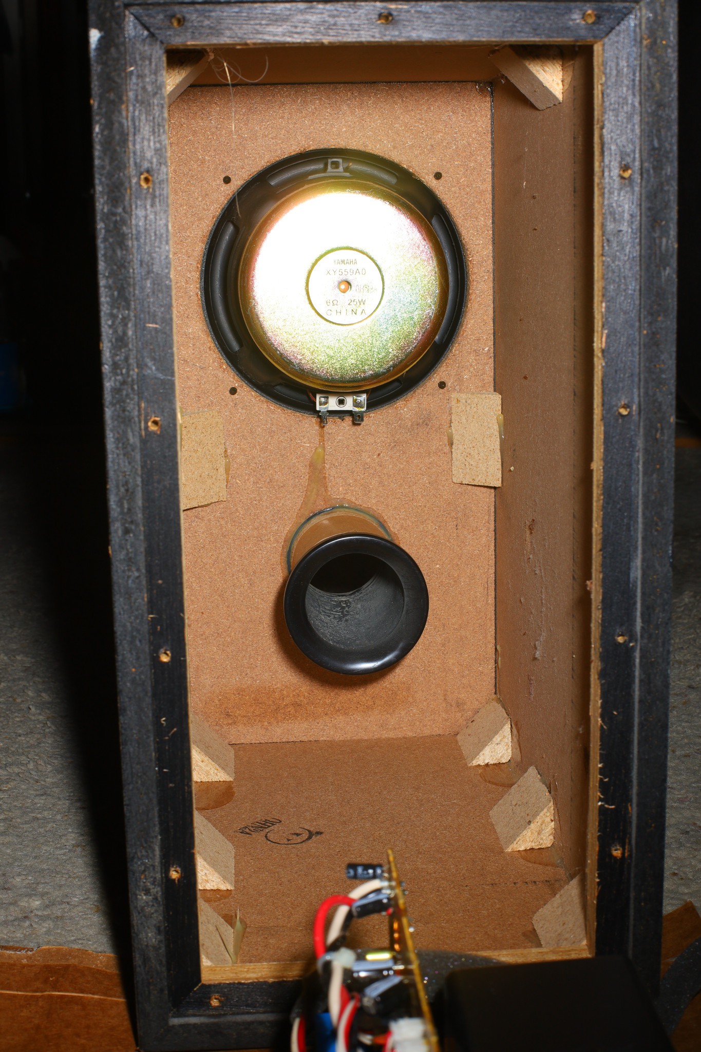
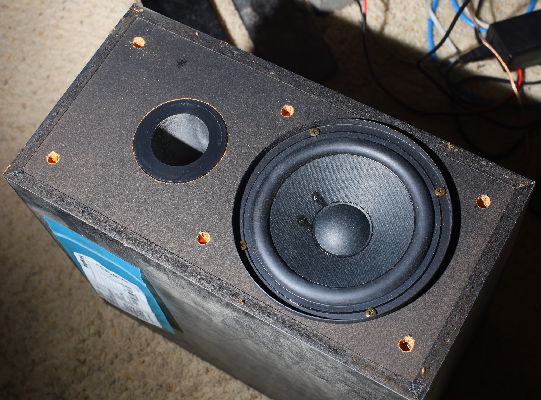
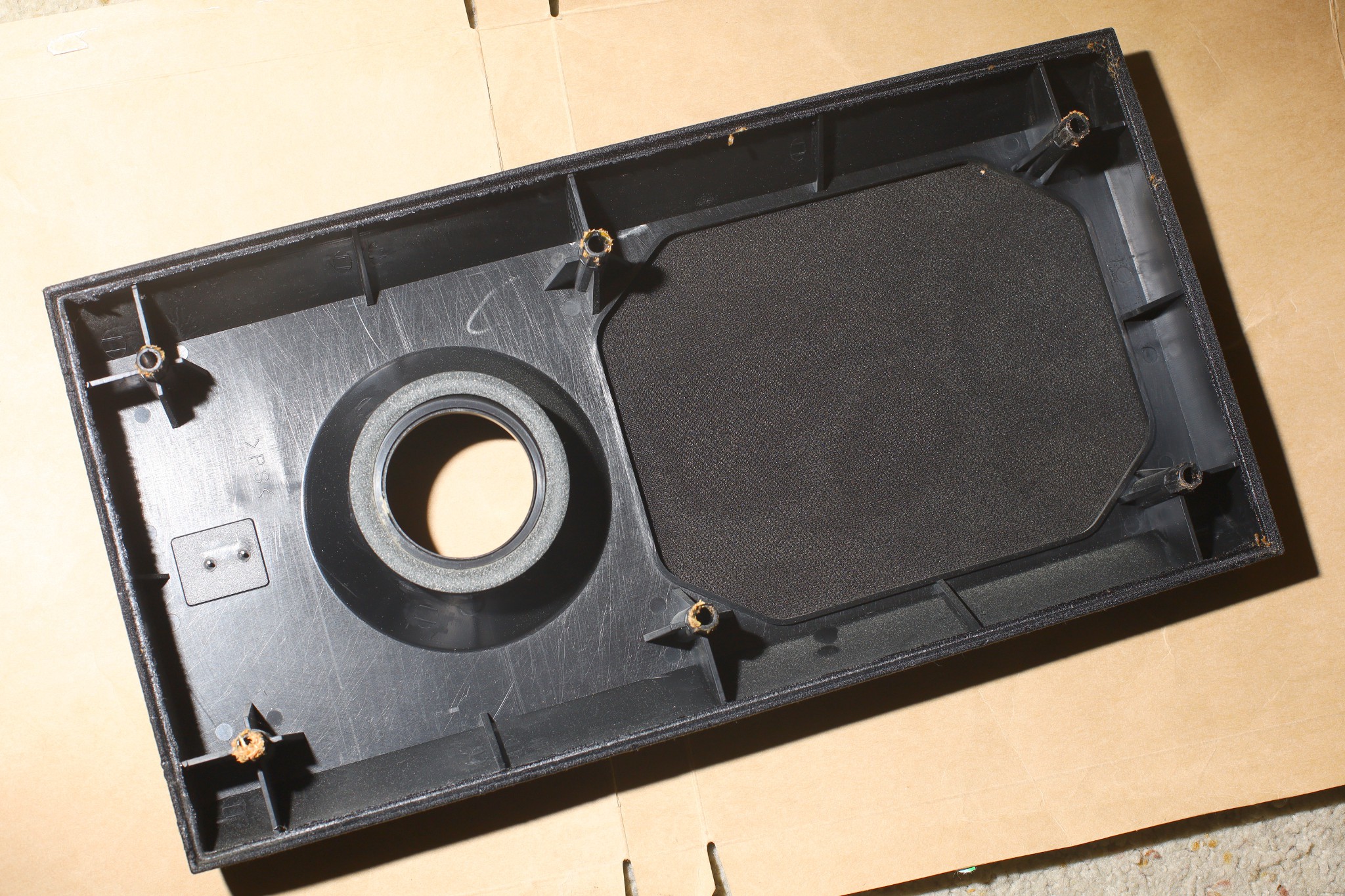
    Finally cracked the fabric off & recycled it, after 25 years.  It's just a 6" & the port is a cardboard tube.  To point up, it probably needs some protective screen.  

    The very smallest desk sized subwoofers have 6" drivers nowadays.  Most have 10".  Lions once had a crappy desk subwoofer in a cube farm.  It didn't go very low.

    The old man's SB-L52's had a 10" woofer in each speaker.  You don't know what you have until it's gone but we didn't have any modern audio sources in those days either.   Music came manely from tape, radio, analog TV until 2011.  2019 brought a big leap in audio processing which further enhanced it.

    Besides loads of critters, the cover had solid, tapered sides so it didn't radiate as well as the uncovered speaker.

    Listening the hell out of the upgraded system, the subwoofer impact depends on the music.  Some music has a lot of it & some has none.  Some music requires more subwoofer gain & some requires less.  It generally makes the sound richer below 200Hz but its full thunder is outside normal music.  Someone has to sit down & play a bass line to make it go but constantly blasting tones at 40Hz causes ear fatigue.  It requires critical listening lions have rarely done since the 90's.  There isn't as much music which gets lions excited as there was 25 years ago.


    The subwoofer gain has gradually worked lower until it might be time to step down the feedback resistor.  The mane volume similarly needs to be stepped down more.  At the same time, the old man's SA-310 tuner & the HTR-5230 were rarely run over 1/4.  It seems to be a marketing tactic to tune the gains way up.

    The desk height affects the subwoofer gain.  It's kind of a return to the days before single band compression.  Multiband compression may be the end game.

    It's never going to be as loud as it was in childhood because lion ears can't take the loudness.  It never gets close to saturating the STA540.  It has intermittent interference, independent of volume level but dependent on speaker cable position.  The speaker cable itself seems to pick up something.  That might explain why subwoofers have integrated amplifiers.

    ---------------------------------------------------------------------------------------------------------------------------------

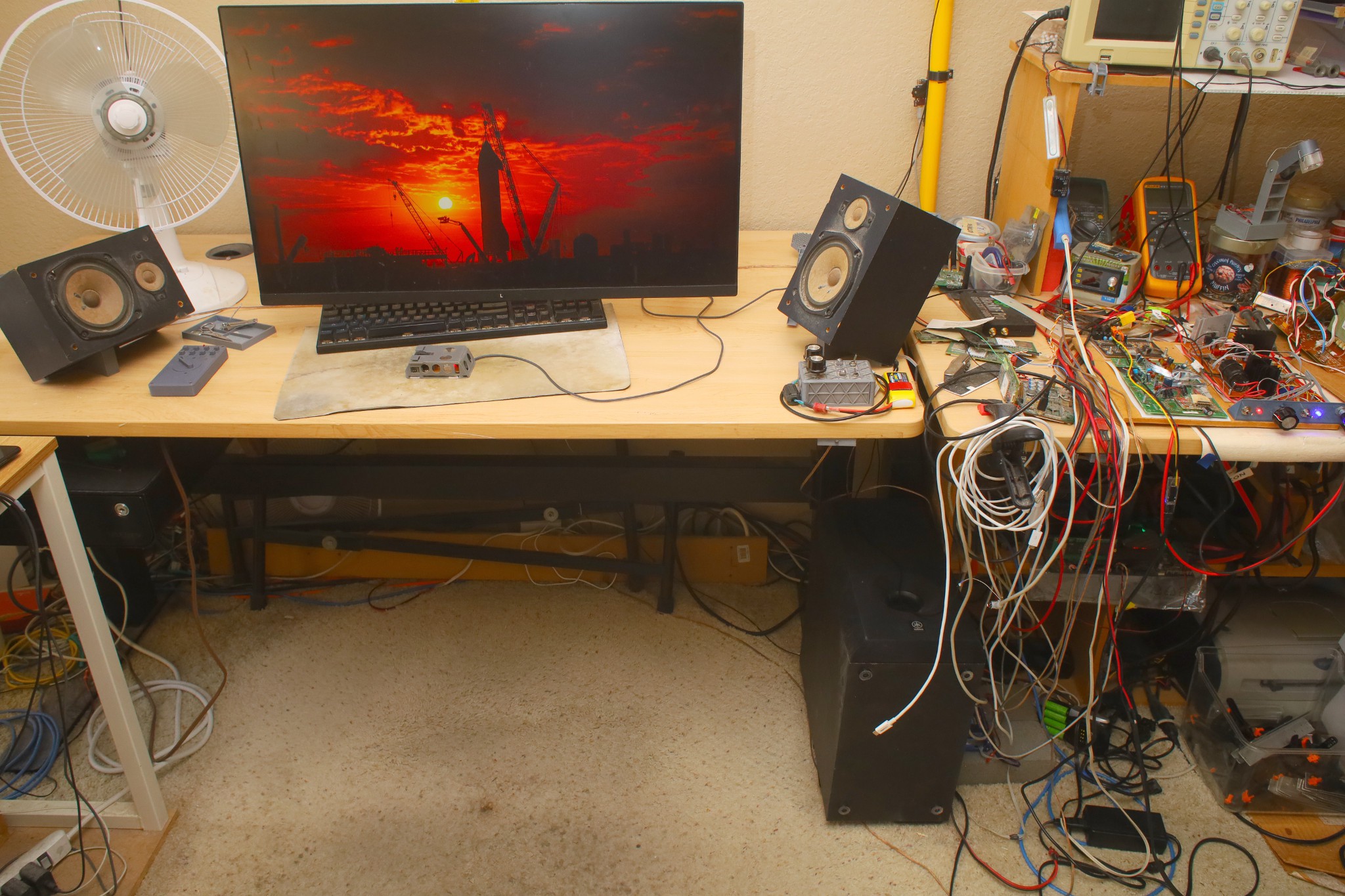
    The next big problem is a permanent location for the amplifier.  It's going to be hard to reach on the bench.  The 10' fiber optic & the subwoofer cable make it difficult to place under the router.  It's going to entail spending.  It seems 2 TOSLINK cables can be joined with a 3D printed part, if you can find a cable locally.

    If lions still didn't use the space for exercise, as it was 25 years ago, there could easily be 2 rear speakers & a subwoofer behind the seat.  There's sort of a case for modular floor transporters which automatically reposition all the gear.  As bad as modern movies are & the housing situation is, there's a case for watching the good movies with a good sound system during the daytime, when no neighbors are around.

  • Front panel update

    lion mclionhead08/31/2026 at 23:56 0 comments

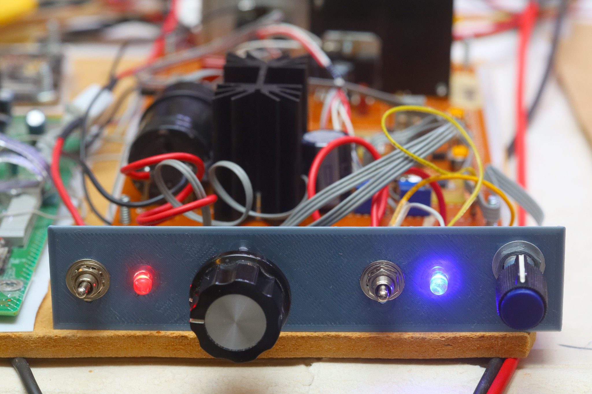
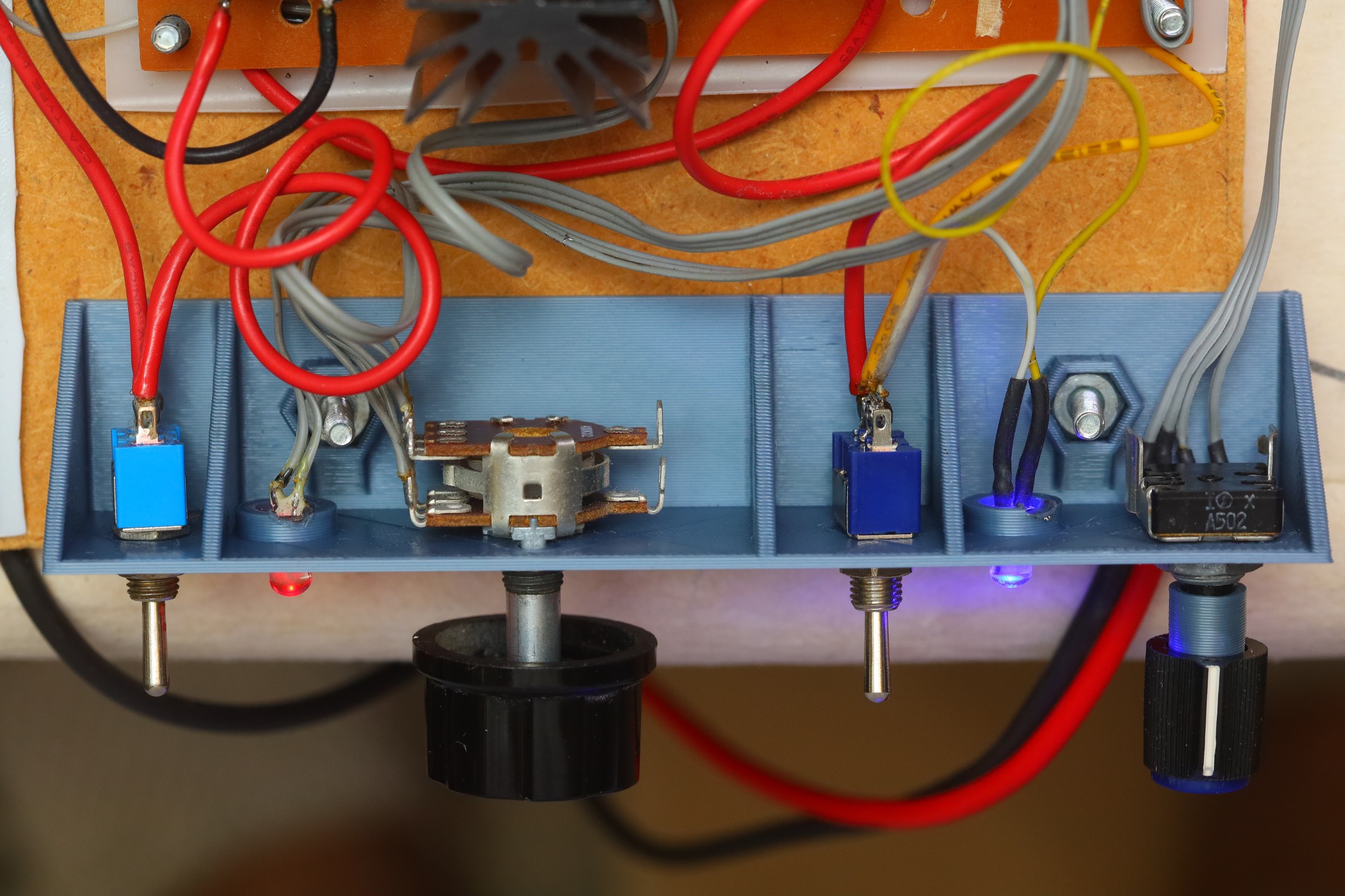
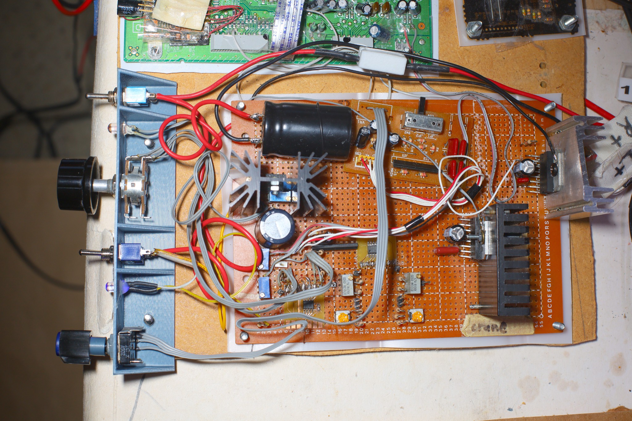
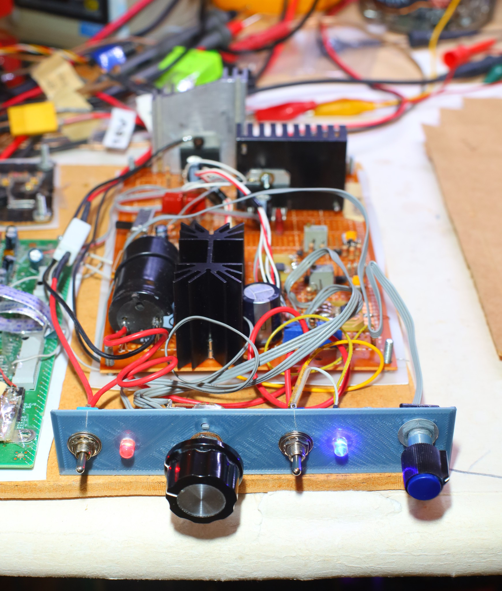
    Moved the subwoofer switch farther away from the mane volume to prevent accidents.  Welded the LEDs on & installed the captive nuts to make it final.  Subwoofer pot barely squeezed by the captive nut, with some bending.

    --------------------------------------------------------------------------------------

    With the woofer pointing up at the desk & the gain stepped up to make 1/2 on the front panel the optimum level, it was a bit louder than the original HTR-5230.  It still vibrates the desk a lot more than it increases the loudness.  The compressor tends to disproportionately boost the bass.  It still all came from the right side.  

    The apartment is officially out of 100k pots.  The last 2 single turn ones are rusted.  Remember when those were down the street in Radio Shack.

    With the EQ applied to the manes & the upward placement of the woofer, it definitely sounds better than it did 25 years ago, but not good enough to be a daily driver.  It takes a lot of space & has proven to not have any setting suitable for neighbors.  With the mane EQ, it's either blasting or it might as well not be on.  It may go down as a toy.  There's enough room to temporarily put it right behind the sitting position.

    There is a desire to play the organ album with it, during xmas season.

    There are better bookshelf speakers for a price.  The current ones were always piss poor.  Verified the tweeters actually do something.  They don't have any low end.

    -------------------------------------------------------------------------

    Pondered scrapping the 25 year old subwoofer & putting its driver in a custom enclosure of smaller size.  The smaller version might fit on the desk, under the monitor.  The fabric on the Yamaha speakers can't be removed without destruction.

    New ones are just big enough for the driver but are super expensive compared to 25 years ago.  The HTR-5230 kit with all the speakers was $400.  New subwoofers start at $200.  A passive radiator for a custom enclosure could be under $50.

  • Subwoofer testing

    lion mclionhead08/24/2026 at 05:39 0 comments

    After 2 weeks of snail mail, the 2nd STA540 went in.  Stepped up the feedback resistor to 20k.  

    Positioned it for future heat sink expansion.

    The subwoofer power & volume are a lot more convenient than stock.  The PLA front panel no longer requires isolation or grounding.  It just needs some captive nuts.  The subwoofer pot needed an adapter to fit the improved knob.  It probably needs some indicators for a more stable position.

    Standby power went back to 7W.

    The useful subwoofer range was only the top 1/4 on the front panel.  Stepped the feedback resistor up again to a 100k pot so it could be dialed into the mid range of the front panel.  

    The STA540 had no problem powering test tones beyond useful levels but it seemed weak during music.  It was easier to feel the bass in the stability ball than hear it.  Recall the stock receiver having the same problem.  

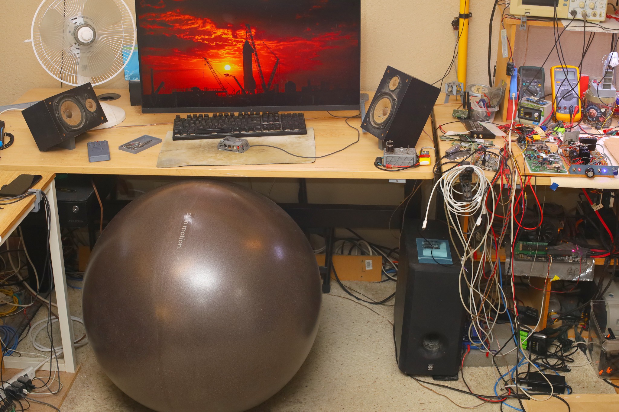
    1st, the manes are being driven harder in the low end than the stock amplifier.  2nd is the subwoofer's unfortunate position.  It was obstructed under a table before 2011 & now is in front of the manes.  The only space has it pointing away from the lion.  A working system would entail sitting far away from the monitor.

    Tried pointing the woofer up, which slightly improved things.  

    There's no relief in sight.  It would take a real man cave costing millions of doll hairs to properly position it.

    ---------------------------------------------------------------

    Modern e-commerce being what it is, the minimum order of STA540 was 2 via 6 week snail mail.  Paying double would have bought 1 from Sparkfun in 1 week.  This is going to provide 6 channels of amplification, if just 1 goes to the subwoofer.  Testing showed 1 into the subwoofer was enough.  There is a TDA7561 in the apartment, but it requires I2C.


    Given 6 amplifier channels, there are 6 channel TOSLINK DAC's for a price.

    https://www.amazon.com/SOUTHSKY-Digital-Decoder-Converter-Optical/dp/B08KD9NVXY/

    https://www.amazon.com/Digital-Channel-Converter-Optical-Amplifier/dp/B0GS5R2K73/

    https://www.amazon.com/Decoder-Converter-Digital-Optical-Concert/dp/B09CDY7862/

    They're either 192khz for 2 channels or 48khz for 6 channels.  192khz for 6 channels seems to require USB.

    The vintage CS4227 can decode 6 channels of I2S but the YM3436 only decoded 2 from TOSLINK.  It used the YM3436 for a legacy 2 channel codec while the YSS908 was decoding a 6 channel codec over TOSLINK, a very hardware solution for handling 2 different codecs.  Since the YSS908 is gone, it will never decode 6 channels again.

    There's always fabricating a TOSLINK or USB decoder out of spare parts, but it would be a big effort.  It would fill the space occupied by the TOSLINK board but wouldn't take any more space.  Then, it might as well have a raspberry pi SPI interface for capturing.  The mane advantage is being able to process the digital signal.  A growing number of gootube channels which formerly allowed downloads are now blocked from downloaders.  

    https://www.youtube.com/@greatperformances/videos

    https://www.youtube.com/@NatGeo

    https://www.youtube.com/@gravitasdocumentaries/videos

    All the long format videos are blocked but the authorized player finally gained barely useful audio compression after a 20 year battle for louder commercials.  It's total dogshit & there's no reverb.  

    -----------------------------------------------------------------------------------------------------------------------

    After many years, lions became satisfied that 6 speakers would be a tangibly better experience.  2 ears combined with head movements produce much more spatial awareness than 2 speakers can provide, the same way eye movements are a key factor in vision besides static pixels.  The center speaker & rear speakers are resolved by...

    Read more »
  • Subwoofer implementation

    lion mclionhead08/18/2026 at 23:37 0 comments

    Turned the power cable into a speaker connection & the active subwoofer became a passive subwoofer.  There was no way to extract the power switch without destroying it.

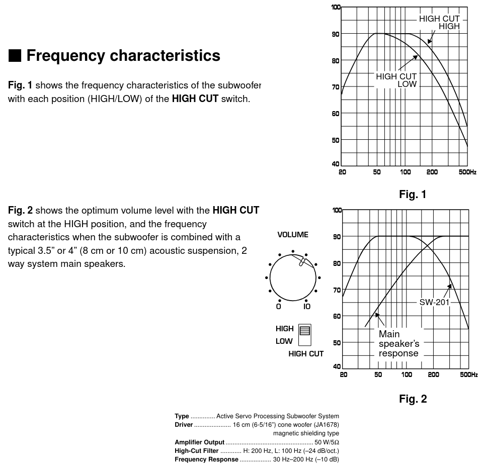
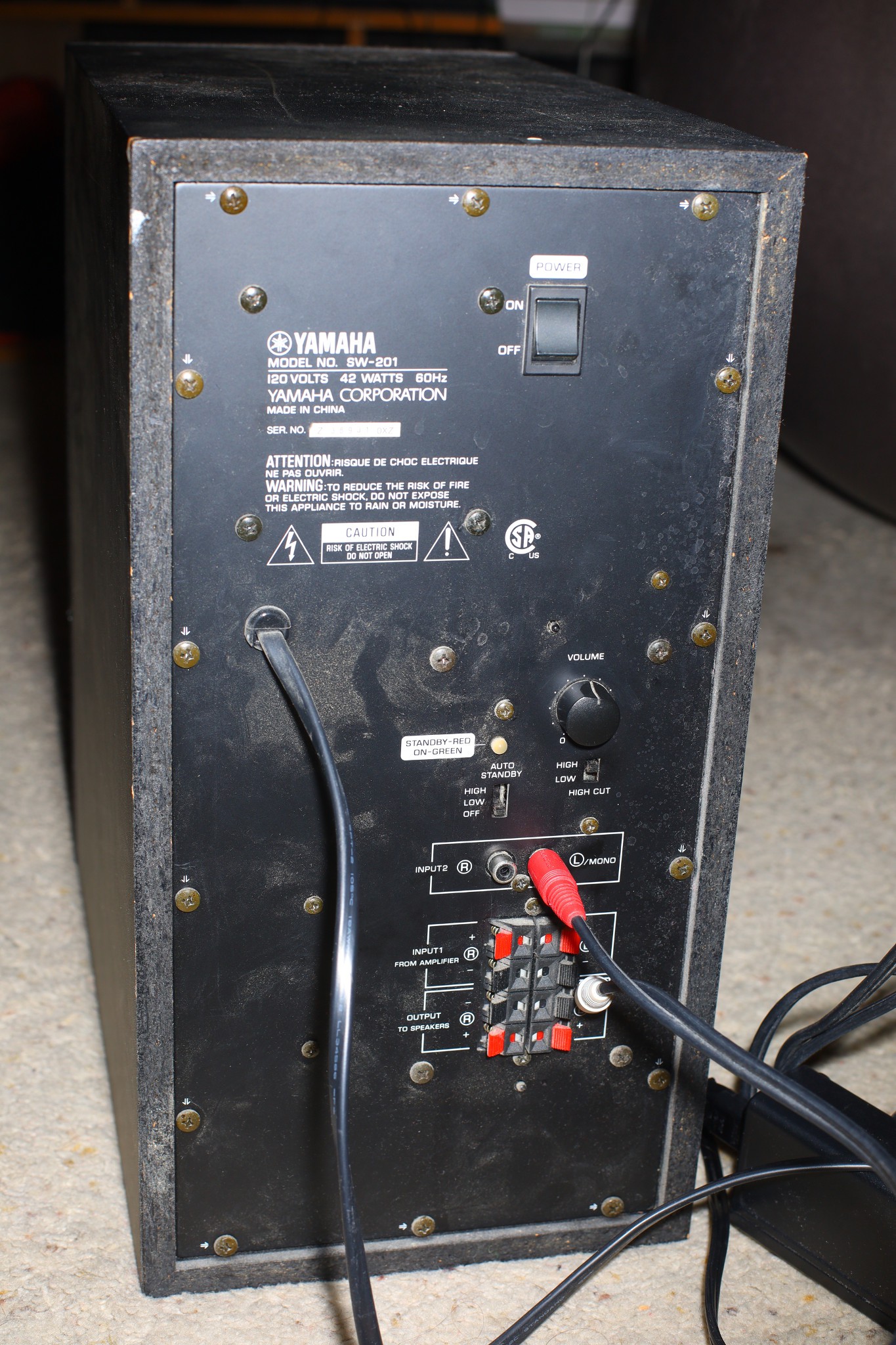
    The SW-201 manual had the original cutoff frequencies.  It had an active lowpass filter while the "active servo advanced negative impedance" amplifier blocked DC.  It had an optimum volume level which lions never used.  The high cut was intended to merge it with the manes. What lions remember was a large gap between the manes & the subwoofer which distinguished it from the 3 ways of childhood.

    The woofer is not the way to truly get back the sound of childhood.  Better manes than these recycled ones might do the job, but the sound of childhood never was as good as what lions remember.  The childhood speakers were in odd, off center positions, playing non ideal tapes & radio stations.  It wasn't worth the hassle so the parents usually ran the TV speakers instead of the audiophile speakers.  They only briefly ran the audiophile speakers loud in 1983, playing xmas organ music.

    Started inspecting the SW-201 for parts which could be used for a lowpass filter.

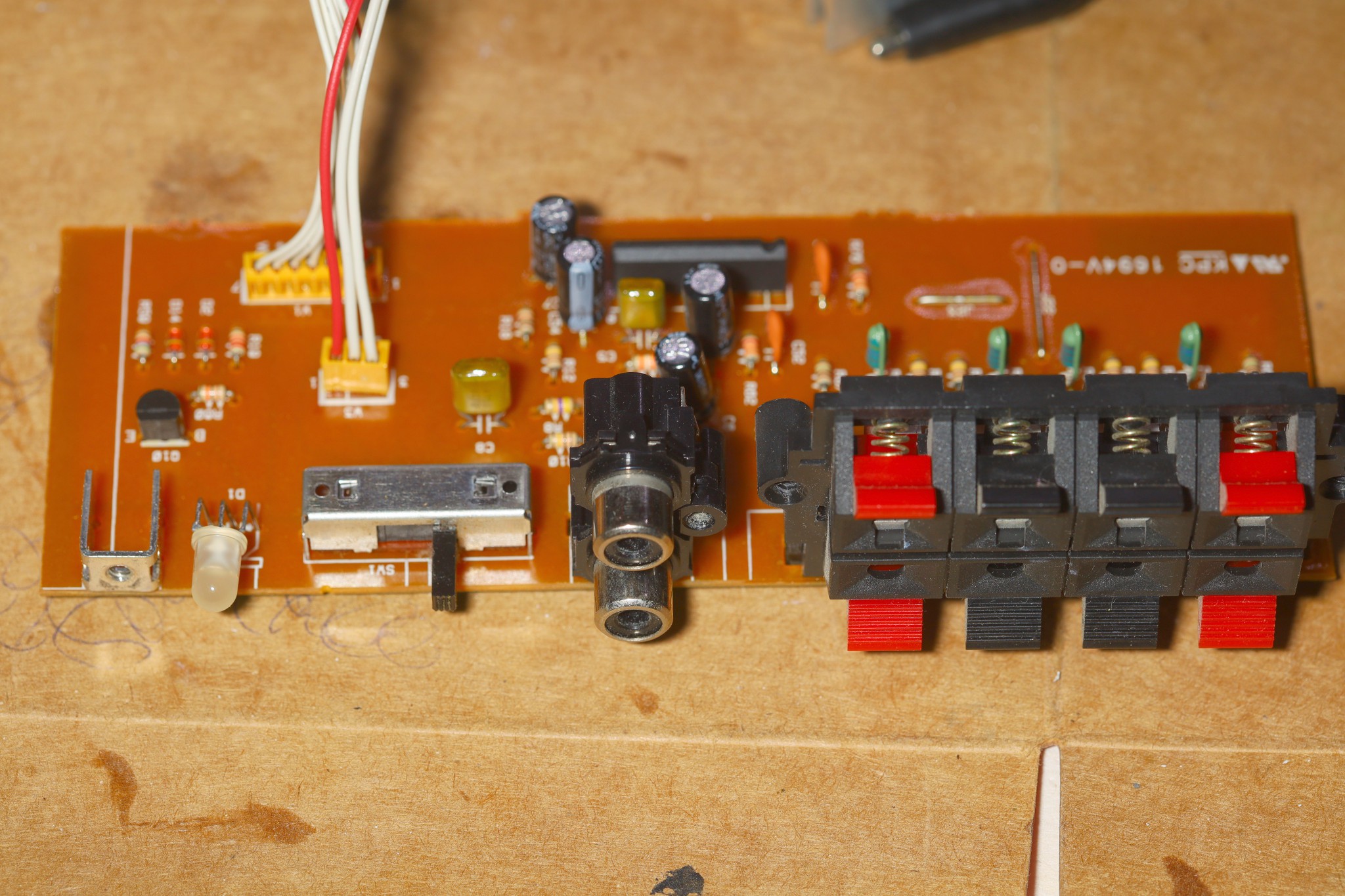
    This board just buffered up input from the many choices & had the auto standby selector.  

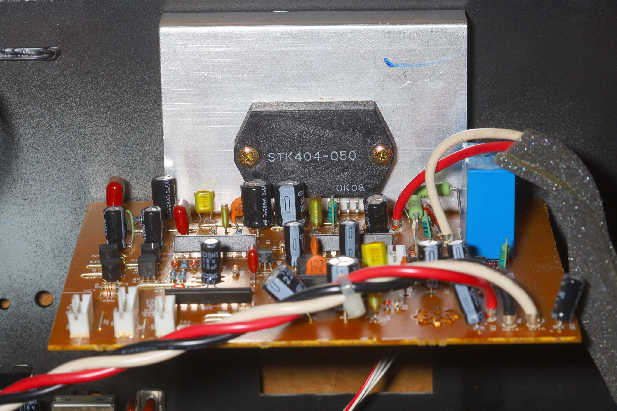
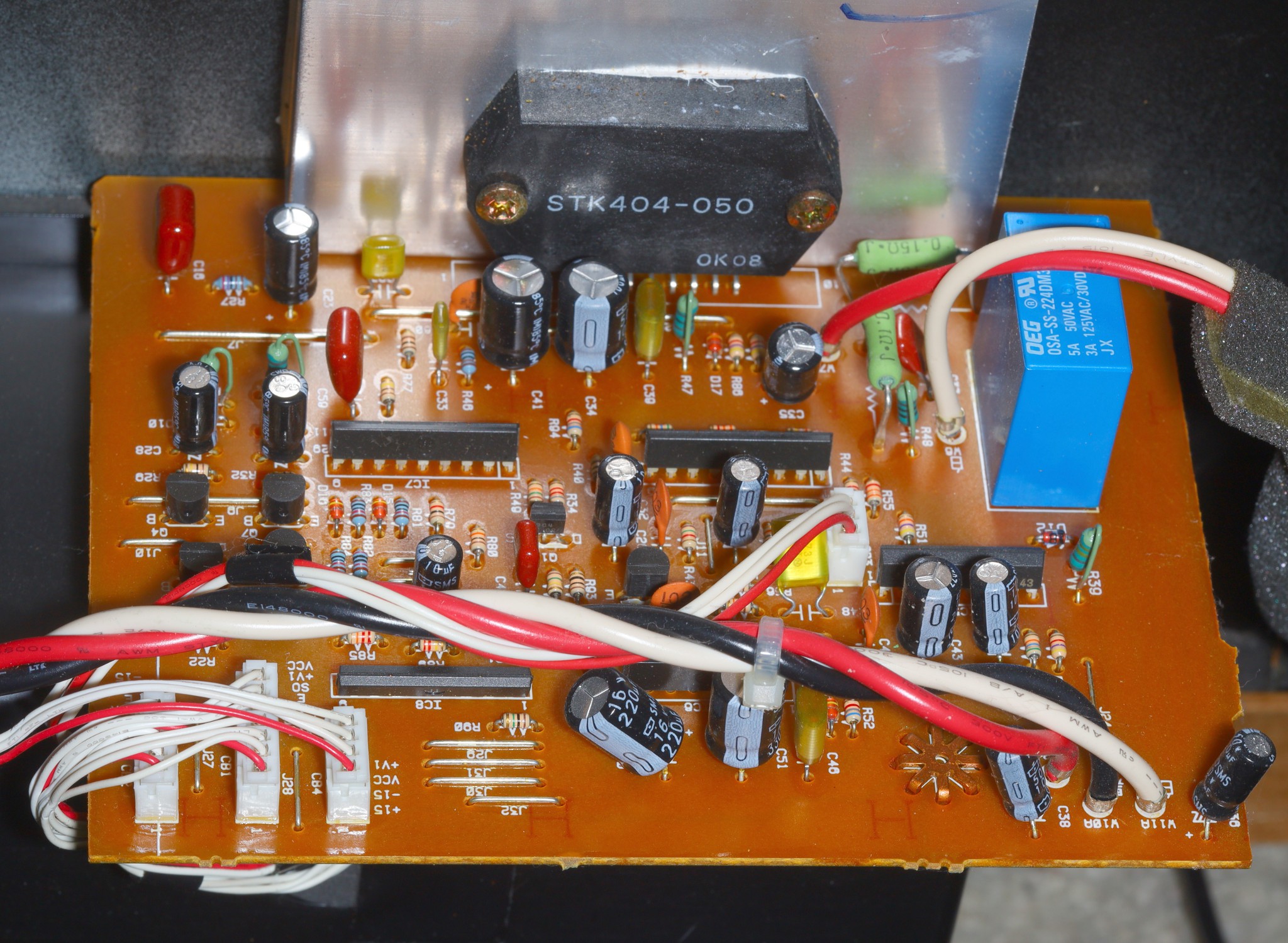
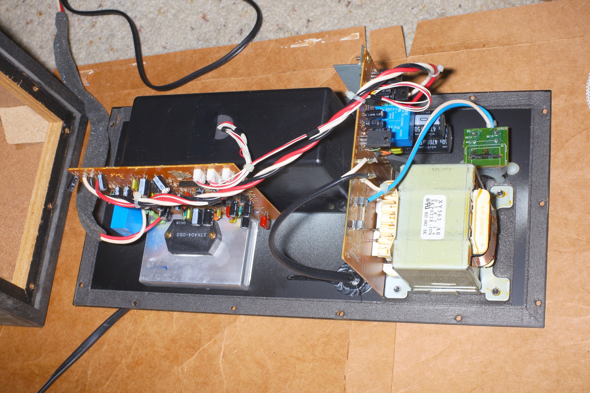
    This one just had the "advanced negative impedance" power amplifier.  Lions already give negative impedance.  The STK404 requires a boat load of passives & a true negative rail.

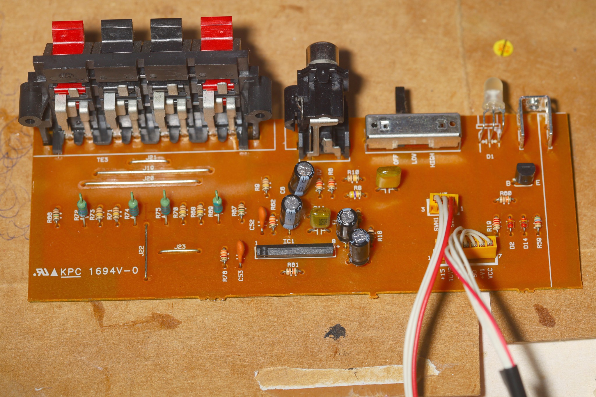
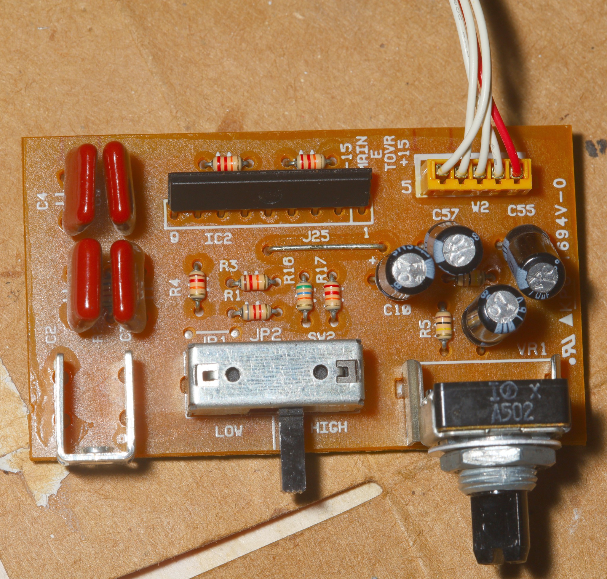
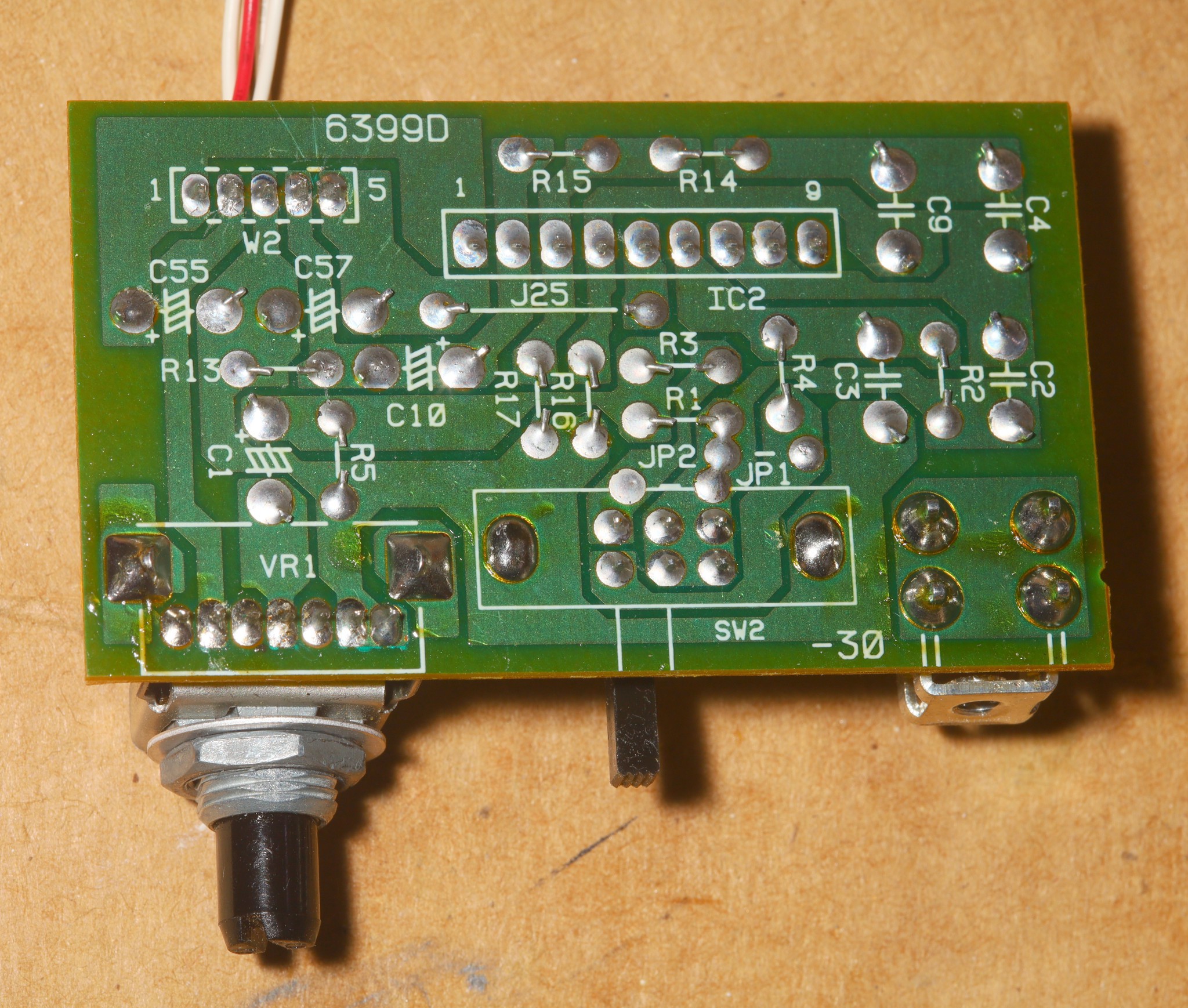
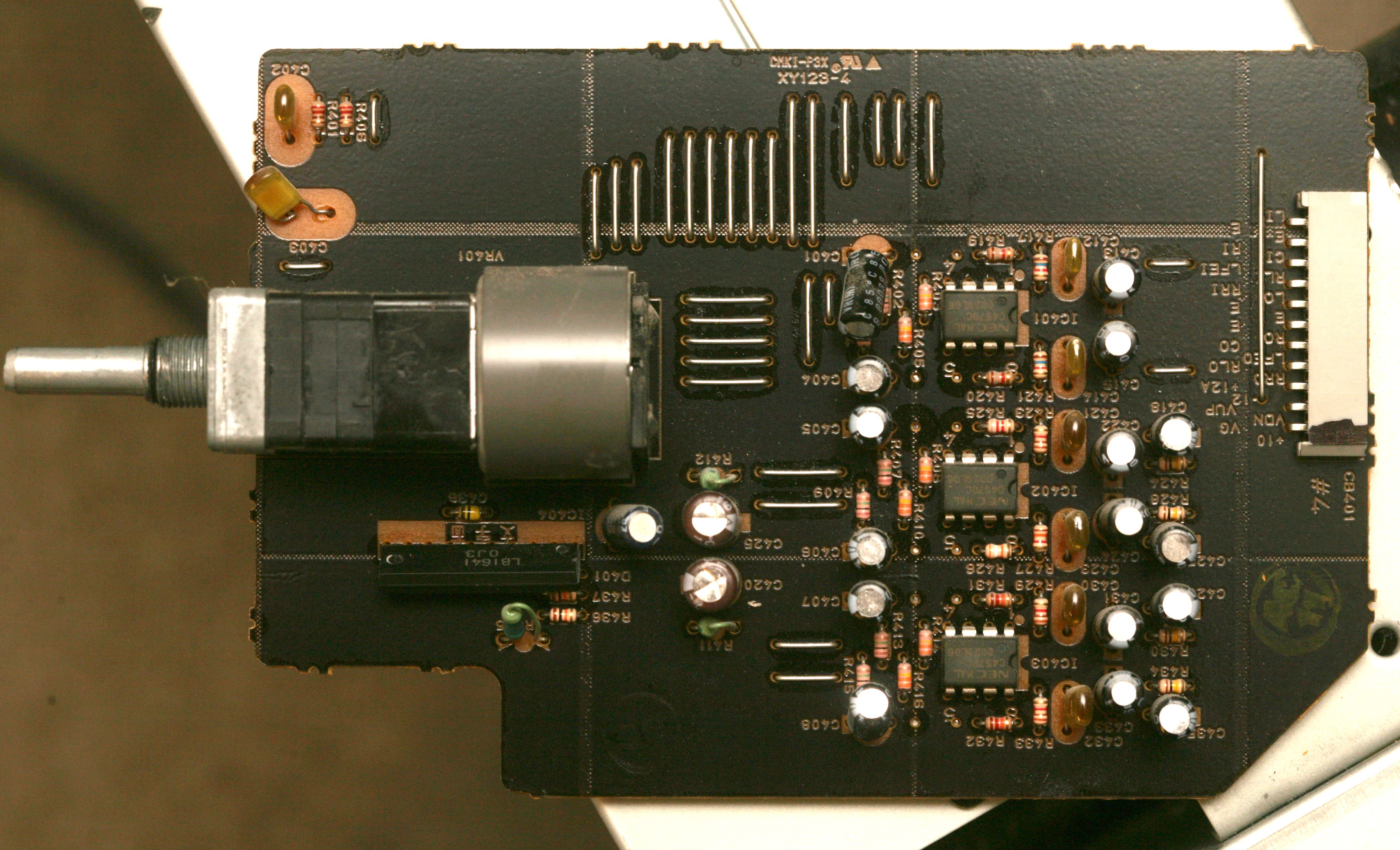
    The lowpass filter was entirely a standalone circuit on the volume control board.  MAIN was the output. TOVR was the input.  It accepts +15, +5, & GND in place of +15, E, & -15.  It's a low impedance input so it needs a buffer of its own.  It's non inverting while the EQ is inverting.  Its buffer needs to invert to get the same speaker polarity.  Not very optimistic about that 25 year old, 5k pot's longevity.

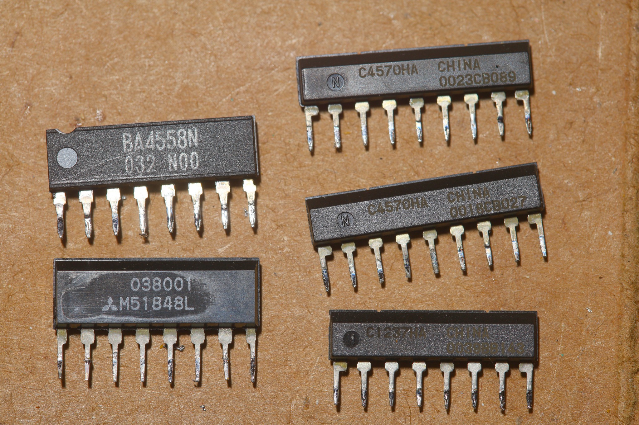
    The woofer yielded some BA4558 1V/us & C4570HA 7V/us  op amps.  Helas, the mighty LF353 does 13V/us but these are the best through hole op-amps in the apartment.  C1237 is an overload protection.  M51848 is a timer, probably for the standby mode.

    -------------------------------------------------------------------------------------------------

    The volume output was stepped up from +/- .5V to over +/- 1V to give more juice to the subwoofer but any more juice above +/- 1V made the EQ audibly clip.  The volume probably needs to stay below +/- .5V & the subwoofer probably needs more gain.  A scavenged C4570HA from the subwoofer provided a 2nd gain stage, in addition to buffering it.

    The 2nd STA540 got put on the 1 month snail mail plan, so lions couldn't use the subwoofer until mid september.

    Despite every effort at ground strapping & optimizing the voltages, it's pretty crappy compared to a new commercial amplifier. Through hole perf board collects a lot of noise.  It needs a faraday cage.  An old commercial amplifier is a different story.  It starts out sounding perfect, but the relays & transistors go bad.

  • 15V conversion & subwoofer test

    lion mclionhead08/16/2026 at 20:31 0 comments

    Discovered all GND on the DAC was hooked up to the mane GND instead of the 5V virtual GND.  The 5V virtual GND was the 5V supplying the DAC.  Regulated 12V was the 25V on the DAC.  10V was only used for the MAX412.  The heat sunk LM7805 was the 5V & the bare LM7805 was the 10V.

    5V virtual GND would stay & be migrated to the LM317.  The 10V & the regulated 12V would move to the 15V in.

    DAC -> divider -> Volume -> subwoofer/line level -> baxandall EQ -> divider -> power amplifier

    Baxandall EQ has a low impedance input & low impedance output so it has to run at line level.  Its output has to be divided down to amplifer input level.

    A lot of parts disappeared.

    That had a few problems.  The 3A 15V USB faulted on the inrush current.  Hooking up the subwoofer mixer caused all the output to be mono.  We had a non reproducible clipping & non reproducible noise.  At minimum, it's going to be a lot of voltage followers.

    ---------------------------------------------------------------------------------------------

    For some reason, young lion never marked the push pull pairs of the speaker outputs.  There was a 50/50 chance of cross wiring the speakers & getting mono.  That got the subwoofer mixer to work.

    The clipping & noise was caused by a ground fault somewhere.  Probing showed all the crosstalk to be in the STA540 with the mixing network not creating any crosstalk.  It seems the STA540 heat sink needs to be grounded separately.  Adding grounding straps to every metal object & insulating everything from the wood got the noise down.

    Firing up the subwoofer after 15 years, it had a nasty AC hum.  It has its own facility for mixing down stereo input.  It might need a lower impedance signal than a blocking cap.  The subwoofer is isolated so it could be floated to virtual GND.  Helas, that did nothing.  The AC hum tends to start random times after it's powered up, pointing to a dead cap or broken solder joint.  Power cycling it or whacking it makes it go away for a certain amount of time.  When it works, it makes lions wish they had the $4M for a detached house, $600k when the speaker was new.

    The worst case is another STA540 directly powering the subwoofer with a lowpass filter.  

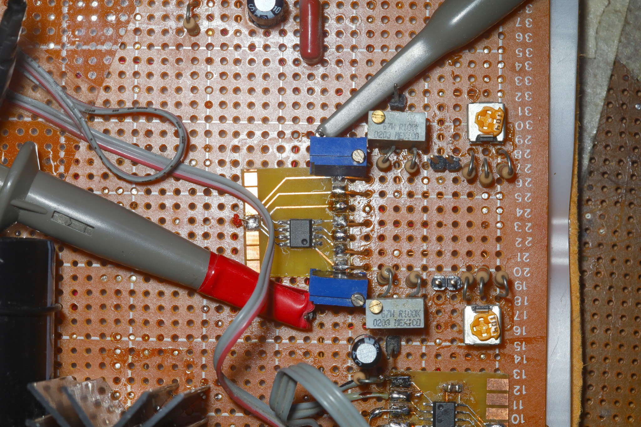
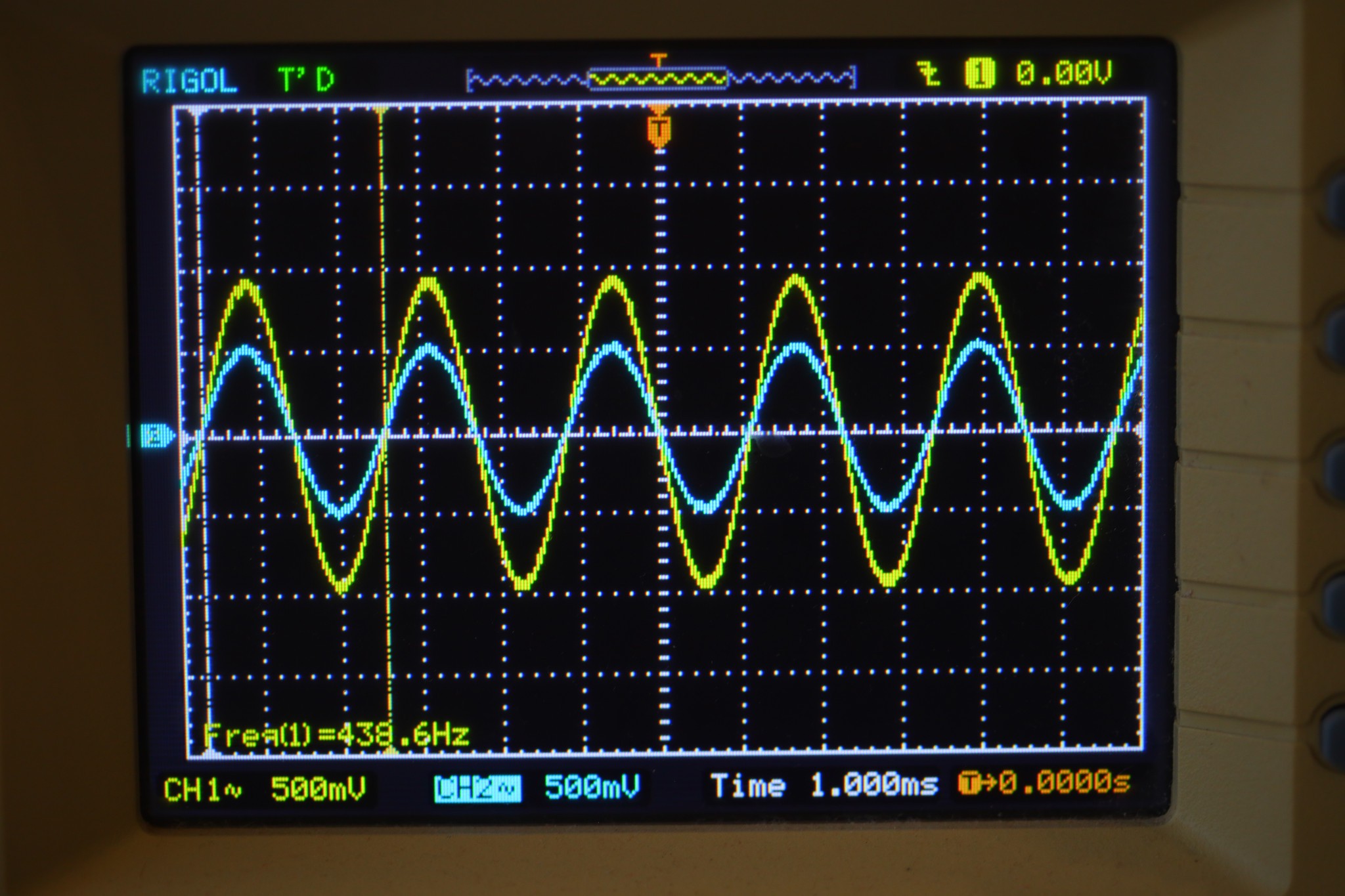
    In the interest of only passive networks, adjusting subwoofer gain entails generating a sine wave in the flat 1khz EQ range, viewing the manes & subwoofer output of both channels on the scope, adjusting 1 channel at a time so the manes match & are a fraction of the subwoofer stage.   The subwoofer itself has another pot for field adjustment.

    ---------------------------------------------------------------------------------------------------------------------------------------------

    A painful teardown of the subwoofer revealed relays, over stretched ribbon cables, chip amplifier, & lots of spider webs.  These are typically perishable parts.  The easiest next step would be a dedicated STA540, lowpass filter, dedicated volume pot for the subwoofer.  A speaker wire would go to the existing cabinet.  The idea is to have easily replaced parts.  The front panel would need another pot & switch.  Basically, the whole thing would be rebuilt.

    There are subwoofer kits & preamps.  They historically needed constant replacement & were higher priced.

  • Pondering a 15V upgrade

    lion mclionhead07/27/2026 at 08:50 0 comments

    Lions came to possess a spare 15V 200W meanwell after the failed inverter project.  More importantly, the 15V had a ground.  That could bring a meaningful improvement in noise.  Of course, there are also some new USB-C bricks with 15V 3A that would use a lot less space but don't have ground.

    Reviewing the prospects of upgrading to 15V, the LF353 for EQ maxed out at 18 & the caps maxed out at 16.  The MAX412 for volume control maxed out at 10.  STA540 maxed out at 20.  The scavenged DAC used 5V & max 25V at high current.   The virtual ground was 5V.  The 12V rail would switch over to direct 15.  It was using noisy LM7805's to get the 5 & 10V.

    Would convert the STA540, DAC, LF353's to direct 15.  The MAX412 would be replaced with another LF353.  The formerly 12V LM317 would supply a 5V virtual ground & DAC.  Just 2 voltages for the whole thing.

    SUBWOOFER NOTES:

    Lions came to desire a subwoofer.  This would need the average of the 2 channels coming from the volume stage & probably another gain step.  The STA540 needs much less than line level while the subwoofer needs line level.  A voltage divider could go after the EQ to match the volume control to the subwoofer.  All the EQ pots could be replaced by fixed resistors.  It's basically a fixed EQ like mega bass.

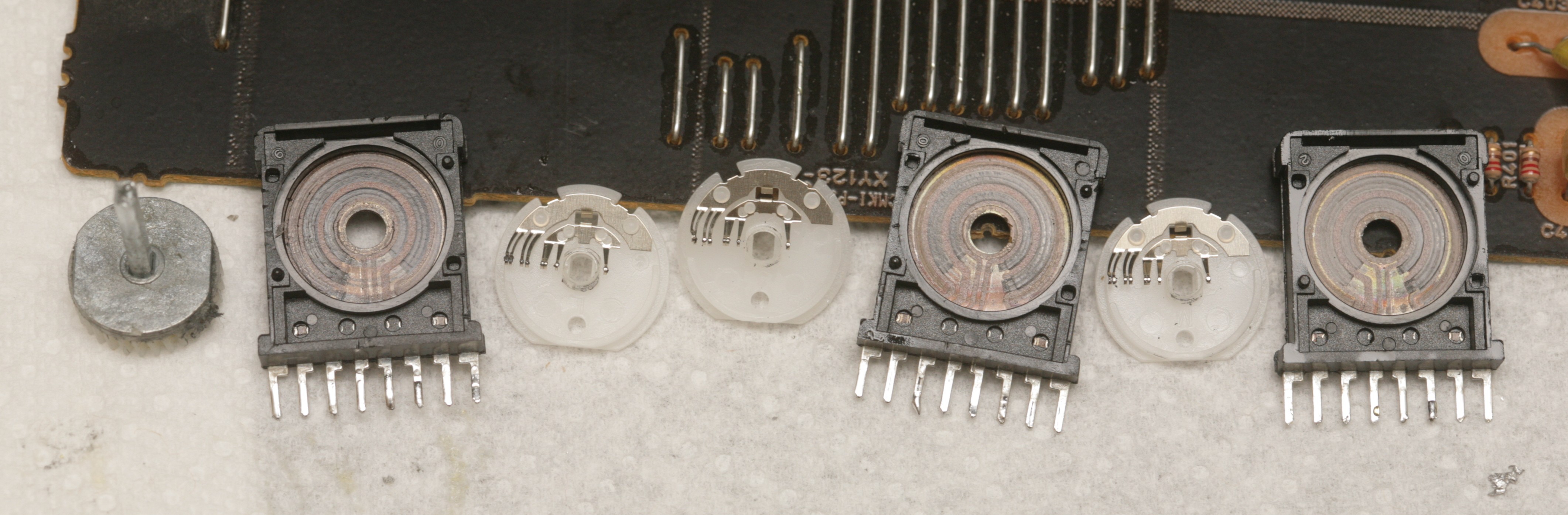
      The original HTR-5230 had separate volume pots for all 6 channels inside the volume control.  It was documented in June 2014.  

    Each layer of a 3 layer pancake had a stereo pot.

    Each pot was a feedback resistor in a non inverting op amp.  Modern volume controls use a VCA.

    The home made amplifier attenuates DAC output in an op-amp with the 2 channel volume control.  This feeds the EQ, which feeds the STA540.  The EQ could read from a fixed voltage divider to get the STA540 input & the subwoofer could read a fixed voltage average from the volume control.  Seem to recall the EQ came between the volume control & STA540.  There's no memory if the HTR-5230 applied EQ to the subwoofer channel though lions are inclined to believe it didn't.  There could be a test circuit for developing a subwoofer tap.  The 100k trimpots in the EQ or the volume control could be repurposed to attenuate the STA540 input, since those controls are dialed in.

    Lions lost interest in capturing I2S or 96khz.  The reliability & lack of noise since grounding the switch panel ended any interest in USB.  It had some residual resets from the other boards not being grounded, but these would hopefully get fixed by the meanwell.

    The effort would entail going several days without any amplifier or possibly using the monitor's speakers.  There's no record of what was being used when the current amplifier was being built.  The apartment might have gone silent when the HTR-5230 died.

    ------------------------------------------------------------------------------------------------

    Of course, the dream system would go back to the 6 channels of lion youth.  It's no longer practical to have a center speaker on top of a monitor.  The center speaker could be the speakers built into the monitor.  It would use a dolby pro logic implementation to expand 2 channels to 6.  That would be a ground up build, probably based on USB, multiple chip amplifiers, digital EQ, digital compression.  It could present a 2 or 6 channel sound card.  It also is impossible to fit the rear speakers in the apartment.  Those days are over but it could be a form of future proofing.

    Note the pro logic encoding only provided a single rear channel.

    Young lion really thought he would eventually have more space & maybe a single family home one day.  The silicon valley thing wasn't going to be forever.  It wasn't a very serious vision.  The vision now is to rely on the fact that...

    Read more »
  • Reducing noise

    lion mclionhead02/27/2023 at 05:23 0 comments

    A jumper from GND to the switch panel ended up killing all the noise.  It didn't stop the growing number of spontaneous power downs.  The panel seemed to be an antenna.  If it wasn't metal, the volume control might need a ground.  The apartment gained a house 12V power supply which would greatly simplify the amplifier.  The tricky part is the wiring from the amplifier to the apartment 12V.

     https://twitter.com/FueledbyLOLZ/status/1681839102361210885

    A living breathing Yamaha HTR-5230 was spotted in the wild.  It must have been on fleebay, since those are incredibly obsolete.  It must have been rarely used.   It made lions miss their more luxurious past of full sized stereo components & $900 rent.  Who knows if all its relays, copper, & heat made the sound any better. 

    Regaining 6 channel pro logic of the past could be a goal.  The rear speakers would have to go on the ceiling.  The center speaker would have to be an over monitor deal.  The subwoofer could bolt on the desk but it wouldn't leave room for sitting.

    When lions had the 6 channel system, they wore glasses full time & sat away from the monitor.  That's why it worked.  Since then, they sit right up against the monitor. 

  • Increasing glitches & a path towards USB

    lion mclionhead08/30/2020 at 00:25 0 comments

    The amplifier followed the path of so many other amplifiers, with increasing glitches over the years.  The lion kingdom could do better.  There's now a 12V brick which could replace the flaming hot 12V regulator.  The recycled HTR-5230 parts which convert TOSLINK to analog have randomly shut down with increasing frequency.


    The plan was to go to an STM32 based USB soundcard.  Since then, the lion kingdom has made sound recorders using a raspberry pi zero W for storage & networking.  They use an STM32 for audio sampling.  Such a thing could use the STM32 to convert USB to a DAC & feed digital audio to the raspberry pi for recording. 

    It would go a step further, implementing dynamic range compression in the STM32.  The raspberry pi would present a front end over wifi, with VU meters, realtime processing options, recording options, but not EQ.  The lion kingdom has only ever had the EQ in a fixed position.

    This might be combined with the CP-33 upgrade to wifi recording.

  • 24 bit 96khz upgrade

    lion mclionhead01/15/2018 at 20:46 0 comments

    After spotting the guy on gootube who said it took only 3 hours to make a USB audio device out of an STM32F4, the decision was made to do it.  The TOSLINK cable evolved out of a need to use the Yamaha intact & defeat power line noise, originally.  The black & green boards were the parts from the Yamaha required just to go from TOSLINK to analog.  

    A custom USB board would be the most efficient way to expose an I2S output so the audio could be sniffed & go to 96khz.  A big win is being able to plug it into a laptop or a raspberry pi.

    Sniffing audio with any software solution wouldn't allow mixing it in a headphone monitor.  

    192khz seems rather pointless for its use.  

View all 9 project logs

Enjoy this project?

Share

Discussions

Similar Projects

Does this project spark your interest?

Become a member to follow this project and never miss any updates