-
More grounding
12/29/2017 at 23:16 • 0 commentsDecided to go over all the grounding on the circuit & separate any more digital grounds from the analog grounds. Lions were previously good at separating motor ground & speaker ground from signal ground, but it seems there was never a notion of separating the signal ground into analog & digital grounds. After much effort separating the 5V into analog & digital sections, the ground was assumed to be an infinite pool of electrons since it wasn't moving anything.
Past ADCs were used for gyros, battery voltage, & photodiodes. It was good enough to ground them to the digital ground. The luck was over with 24 bit audio. Even sharing 2cm of a wire with digital ground introduced noise. All hifi gear has separate digital & analog grounds. Despite flood filled ground planes, much effort is spent separating grounds, making sure the ground paths don't have any bottlenecks.
There were a few places where a digital component had multiple grounds & shared an analog ground path on 1. The STM32 had 1 more digital ground sharing an analog ground. With these all moved to the star, the meter dropped right near -90. The final problem was the wavy DC offset. It was too low in frequency to ruin a datasheet, but it would greatly limit the amount of possible gain in software without clipping.
1/262144 waveform:
![]()
Suspected the op-amp ground was drifting away from the ADC ground, so put a 4.7uF in the audio wire. It greatly reduced the DC drift. The ADC datasheet says it already has a highpass filter in its audio input, but it's rated at a 1Hz cutoff.
Anyways, the audio editor has an ancient tool for measuring sound level. It showed the ADC having -85dB noise peaks & -99dB RMS noise. 13.8 bits & 16 bits based on the ENOB equation. To be sure, 2 channels are averaged & only sampled at 48khz to get those figures.
The formal calculation isn't as warm & fuzzy as counting the pixels in the waveform. If the noise spans 12 pixels in the 1/262144 waveform, just divide 262144/12 & convert to binary to get the number of bits it can resolve. It can resolve 14 bits + some fraction of a 15th bit. The problem is the ENOB equation takes away 1.76bits for a quantization handicap.
-
Capacitor grounding
12/29/2017 at 07:48 • 0 comments![]()
![]()
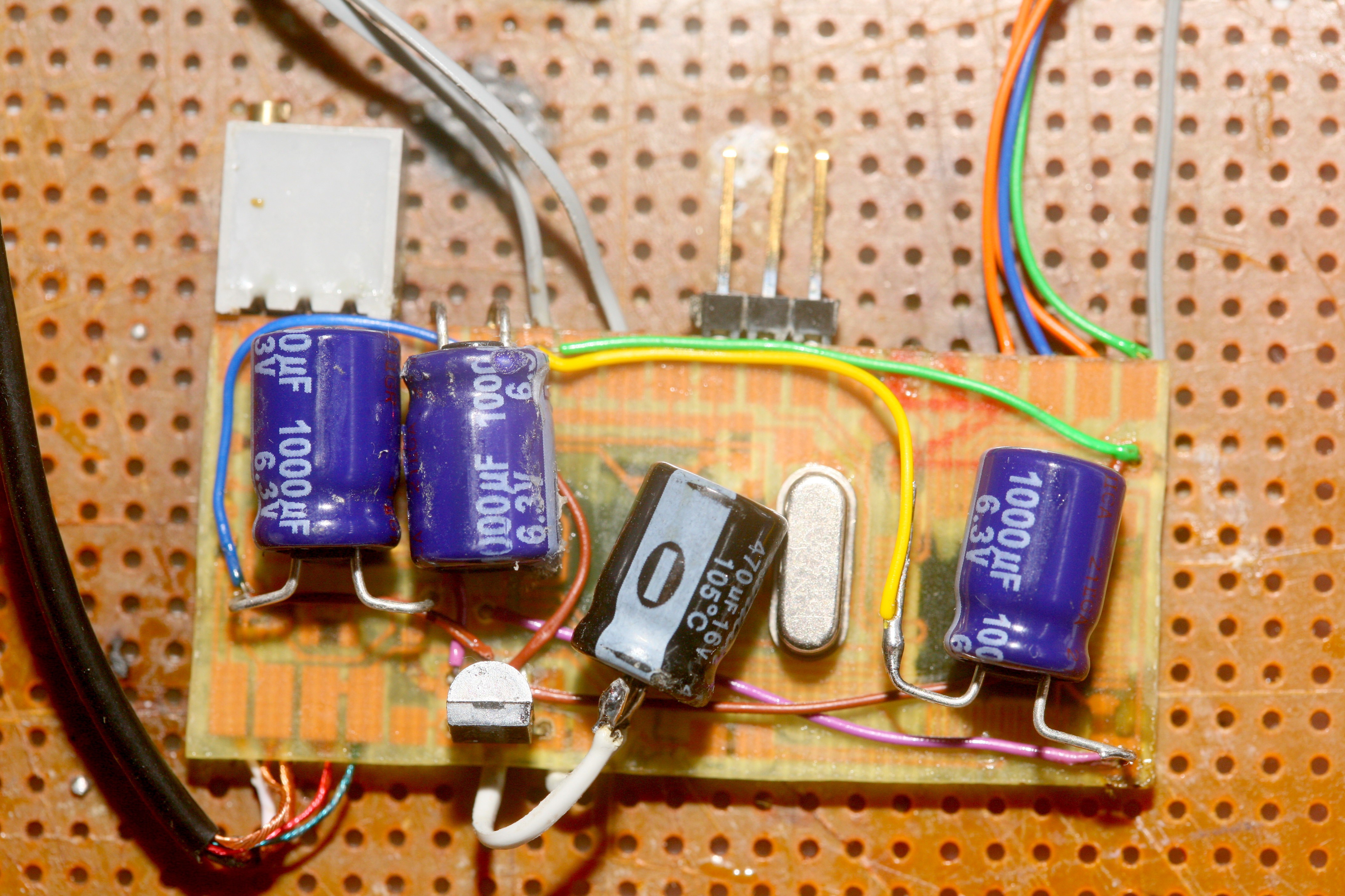
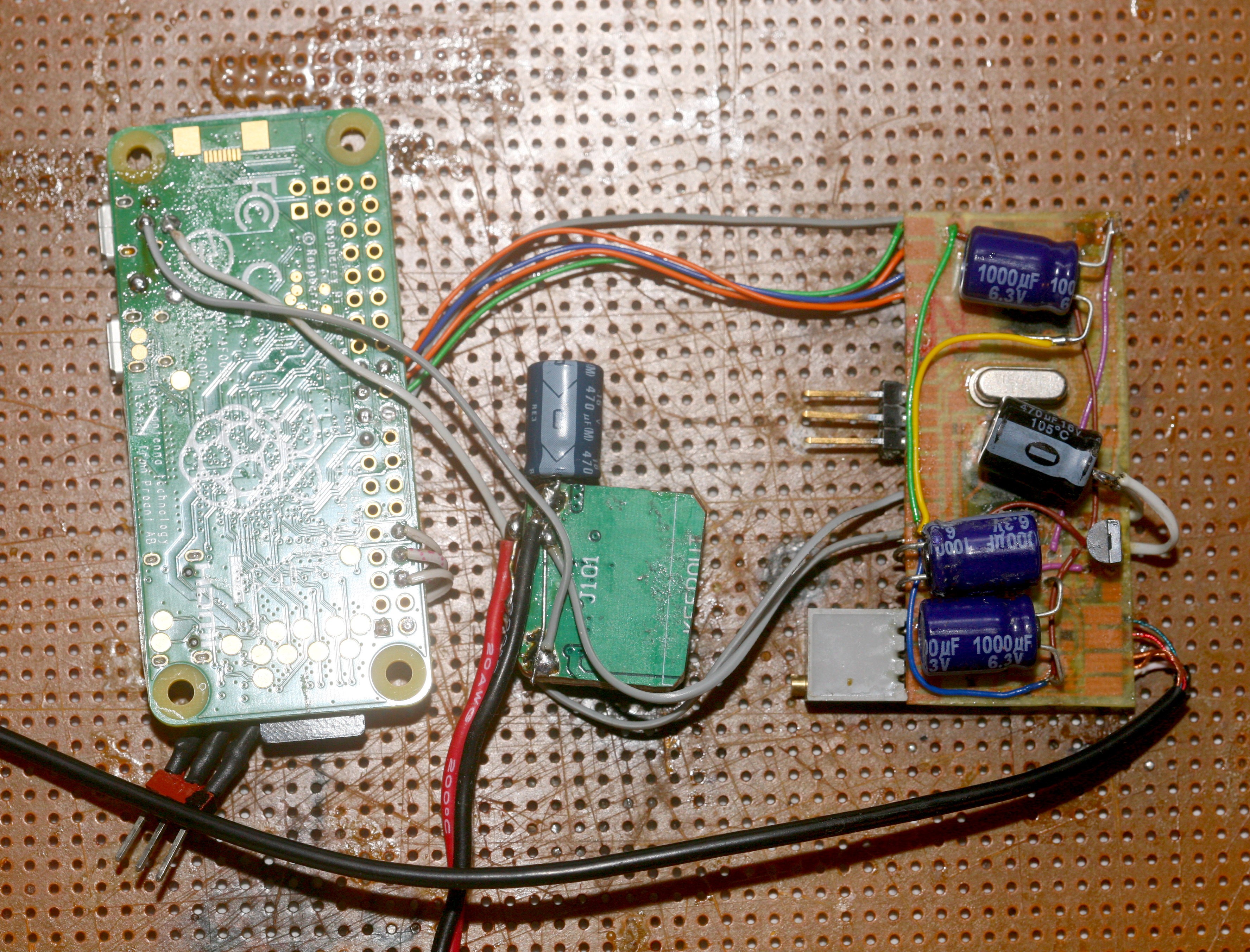
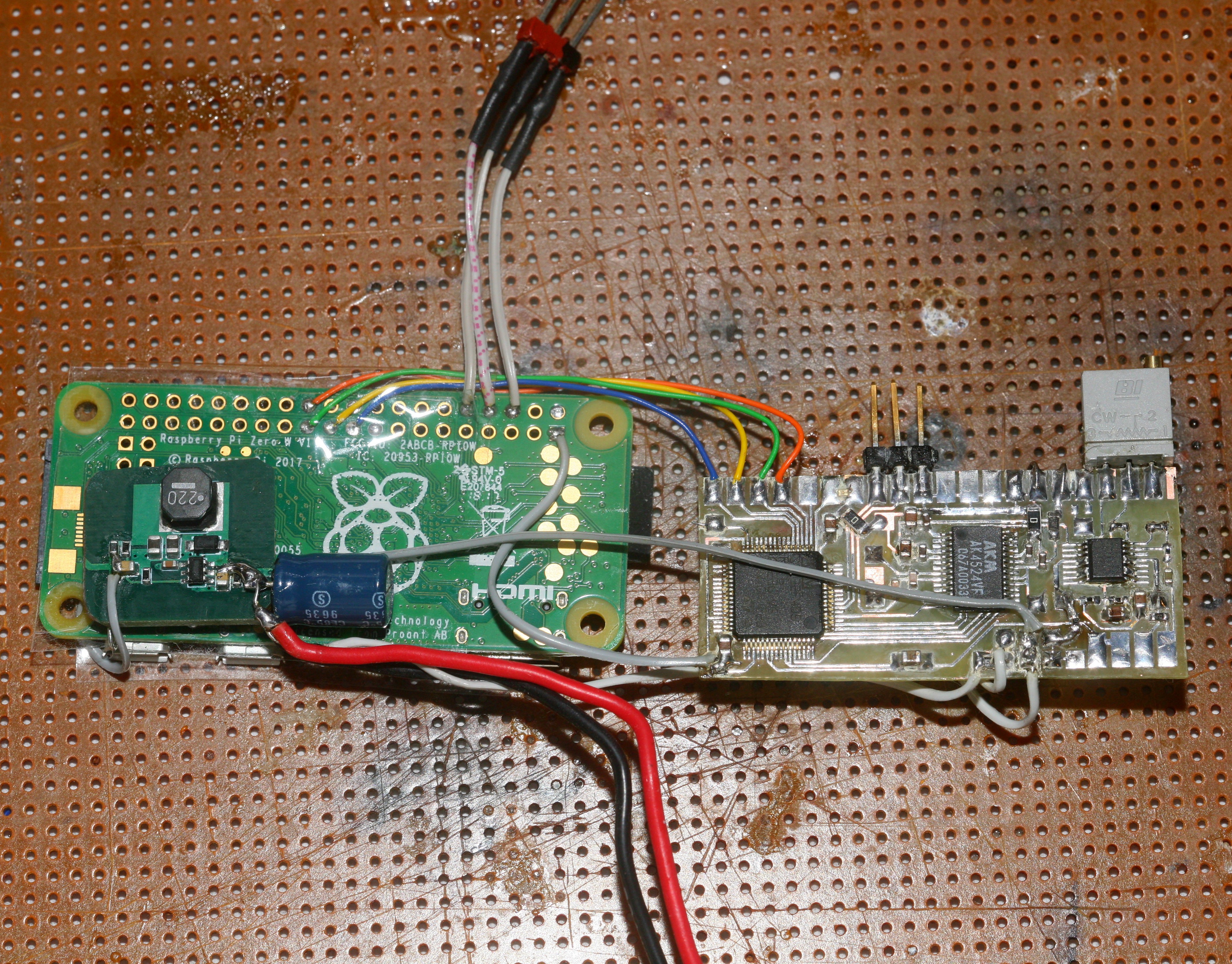
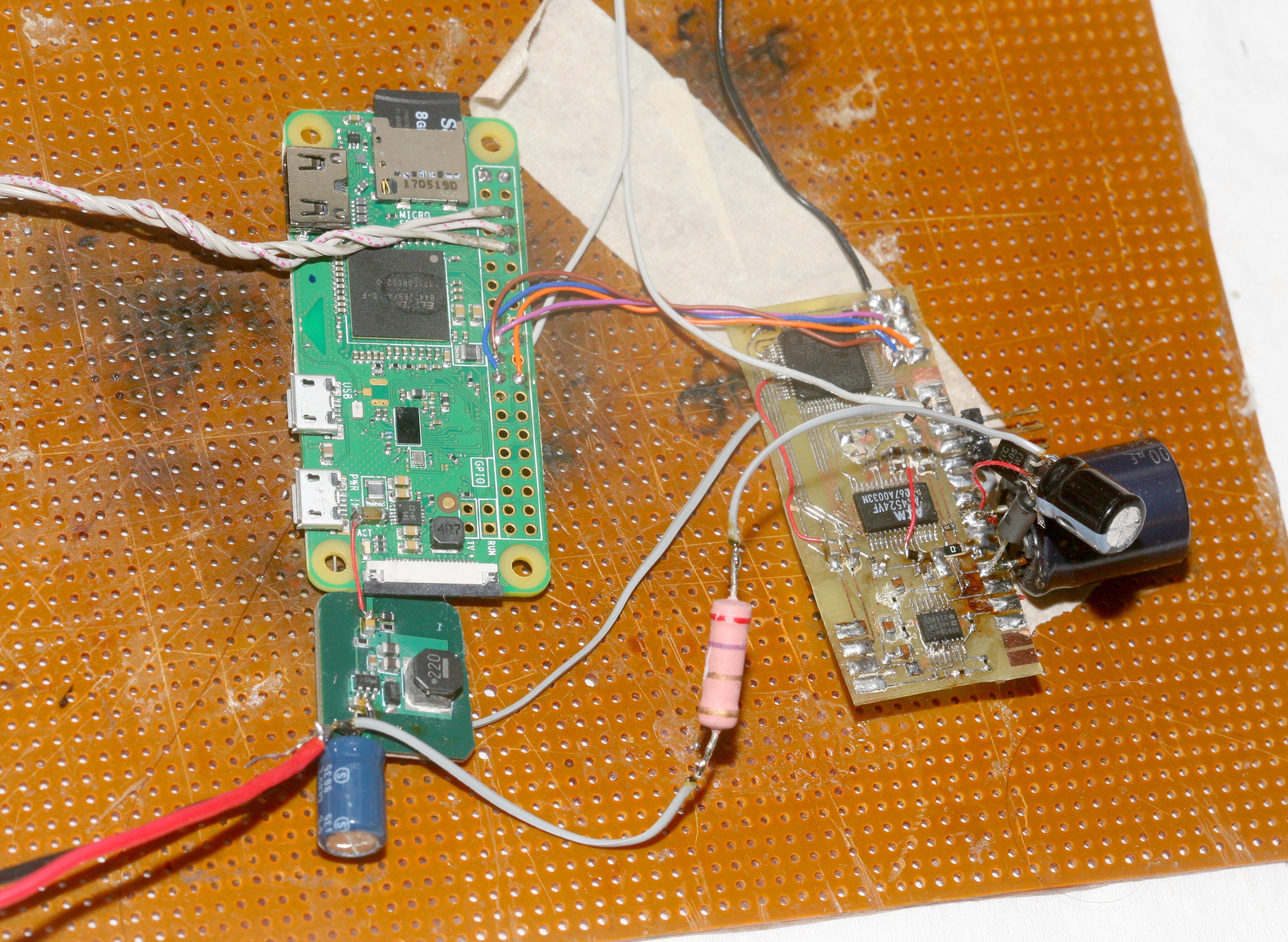
Reviewing blog posts revealed the source of yesterday's noise. It was the 1000uF cap which allowed the STM32 to drive the phones. The new cap required its own separate ground path to eliminate the noise. Sharing its ground with the STM32 ground retained the noise, even though the STM32 already had smaller caps sharing its ground. It was a most perplexing phenomenon.
The best idea is the 3.3V line is a very noisy power rail directly from the PI. The cap short circuits high frequencies to ground, so it could raise any shared ground. All other ground paths from the STM32 would be raised, if the cap shared just 1 STM32 ground path. The smaller caps also raised the ground, but not as much, because they couldn't transfer as much current.
Things would be a lot easier with a flood filled ground. The underside is basically a point to point board, to get the grounding to work. The extra ground path lowered the noise to dead bug territory, but also reintroduced the 2 minute spikes. The 2 minute spikes were much subdued. The STM32 ground eventually shared a mere 2cm ground wire with the analog side. Cutting this ground path from the STM32 ended the 2 minute spikes. Fortunately, the AK4524 was designed well enough to isolate its digital side from its analog side.
Single ended analog audio is pretty soul crushing, but it's actually almost quiet enough to hear aliens. Attaching the phones with 0 gain didn't increase the noise.
-
Headphone noise
12/28/2017 at 07:29 • 0 comments![]()
Another GUI change & the headphone monitoring was working quite well. Not sure why it wasn't tested before, but put the gain to 0 with the headphones connected & the result was what is shown. The noise pegged at -70 instead of -85 & the waveform at 1/65536 was horrendous.
![]()
The headphone was a giant antenna, but it was fortunately not noticeable in the spoken test. It shouldn't affect the Zoom replacement, since that's all differential inputs, but it's worth giving the CM109 a try.
-
Board spacing
12/27/2017 at 02:17 • 0 comments![]()
Finally conceded defeat & spaced the boards out again, as far as possible in the arm band. It was an acceptable compromise for the quality sought after. Slowed down SPI to compensate for the longer cables. The 2 minute transients were gone, although wifi txpower still had to be 5 or below. Soldered in the headset & reenabled the DAC for the 1st time since enabling SPI. SPI immediately started glitching.
3.3V required a big cap to keep SPI from glitching, with the DAC. With the headset being amplified & monitored, the SNR was probably obliterated, but at least it would be the lowest possible. The monitored sound had lots of wifi interference, because the DAC is powered directly by the PI's 3.3V. Surprisingly, it had none of the aliasing which was experienced on day 1.
The quality of the recorded waveform was ludicrous. There was no interference & the fixed gain isolated voice from background noise far more than the phone. The background noise could be amplified to 100% without noticing any interference.
-
Web interface
12/26/2017 at 08:20 • 0 comments![]()
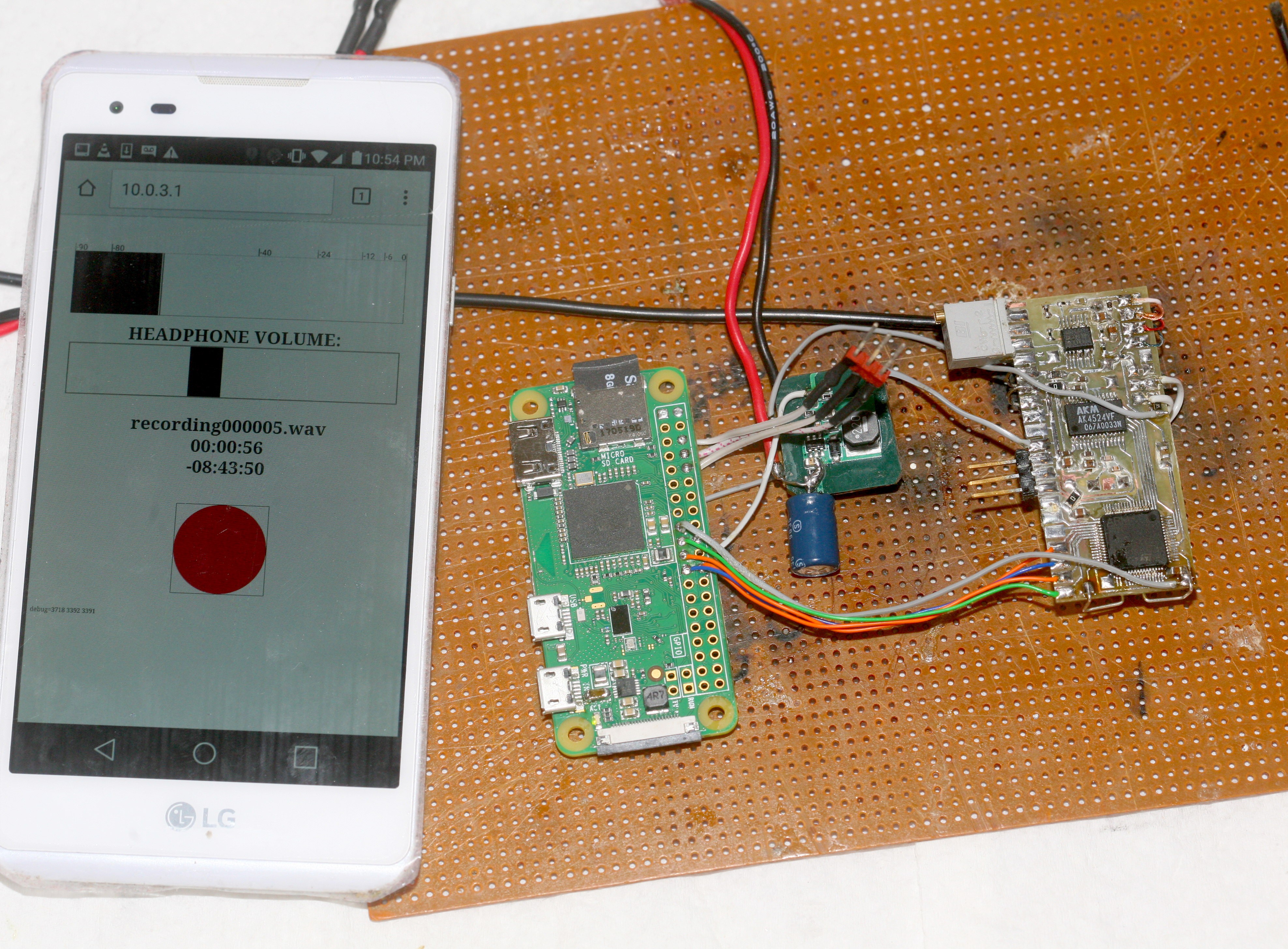
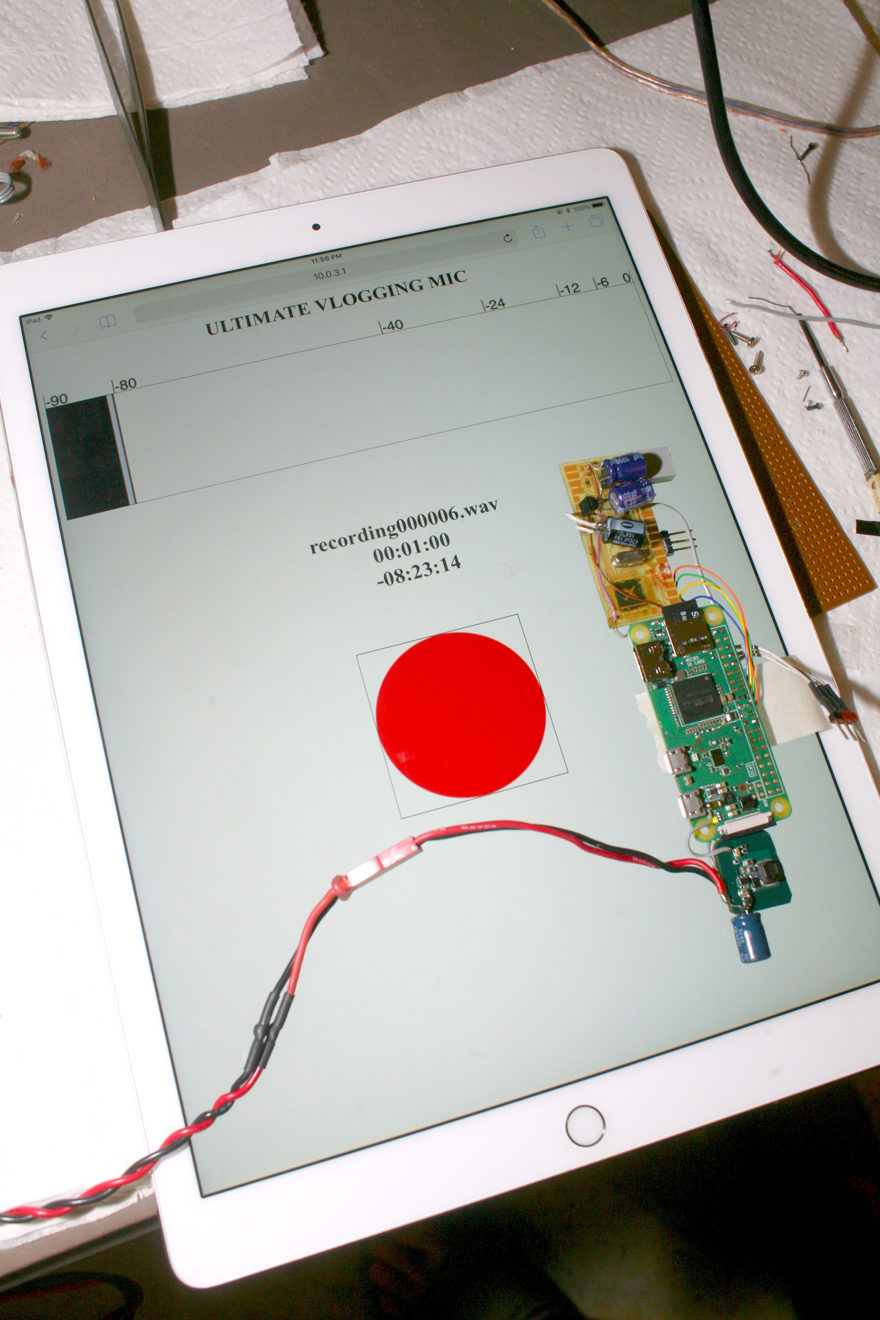
As was envisioned many years ago, the web interface came together. It's a WEB APP, people. It shows the essential peak level, recorded time, time remaneing, & has an unmistakable record/stop button. Don't ask what official combination of AWS, Django, nosql, MongoDB, reactJS, Clockwork, Unicorn, Paperclip, officially sanctioned by 15 year old Stanford graduates at Facebook was involved in this $50 billion buyout target of VU meter web app. The SNR definitely suffers from the VU meter pinging the wifi. If only the REST calls required a billion fewer lines of machine learning.
Of course, putting the analog board on the tablet increases the noise to -80. Properly spaced, the meter hugs -85 or 13.5 effective bits. Turning wifi txpower to 32 pushes the noise to -40. The killer is the longer recordings experience horrific glitches exactly every 120 seconds.
![]()
The other problem is transferring audio files from the PI goes at 8megabits, at best. Wifi is much easier than plugging it into USB & making it a USB device. It'll probably require a WEB INTERFACE to download recordings, which automatically increases the txpower during the download, with something written in an obscure dialect of Heroku.
Where's the cloud service which fixes these 120 second glitches? You can't get a job unless you solve all problems by subscribing to a cloud service.
-
Testing noise with the op-amp
12/25/2017 at 21:58 • 0 commentsFor fear of the op-amp obliterating the waveform, was powering it down & tying the audio pin to ground through 10k to test the noise of the ADC. It turned out, turning the gain to 0 with the op-amp on actually gave less noise on the ADC. Perhaps it was the ADC being actively driven by the op-amp, but the op-amp definitely wasn't injecting noise at 0 gain.
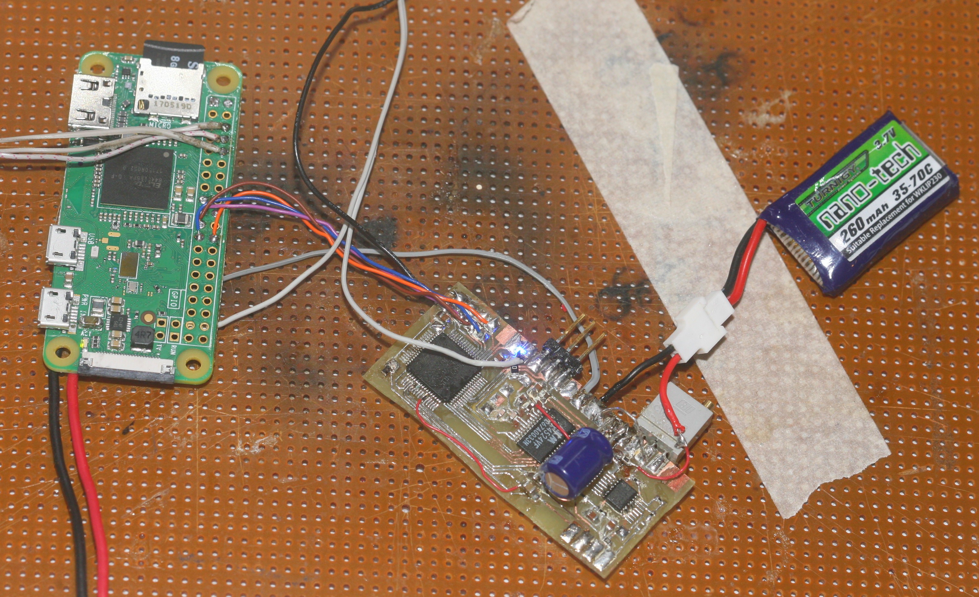
A test with a 4700uF cap made no difference. Moving the 8V-5V converter away from the PI improved it. With the op-amp at 0 gain, the analog section upside down, the waveform was decidedly showing the low 14 bits. Suspect it's noisier because some traces had to be longer than the dead bug. Mounting the boards end on might be adding more wifi interference. Without a flood filled ground, metal film resistors, RF shielding, differential inputs, digital pot, double sided load, it's not going to be perfect. This was the waveform at 1/262144:
![]()
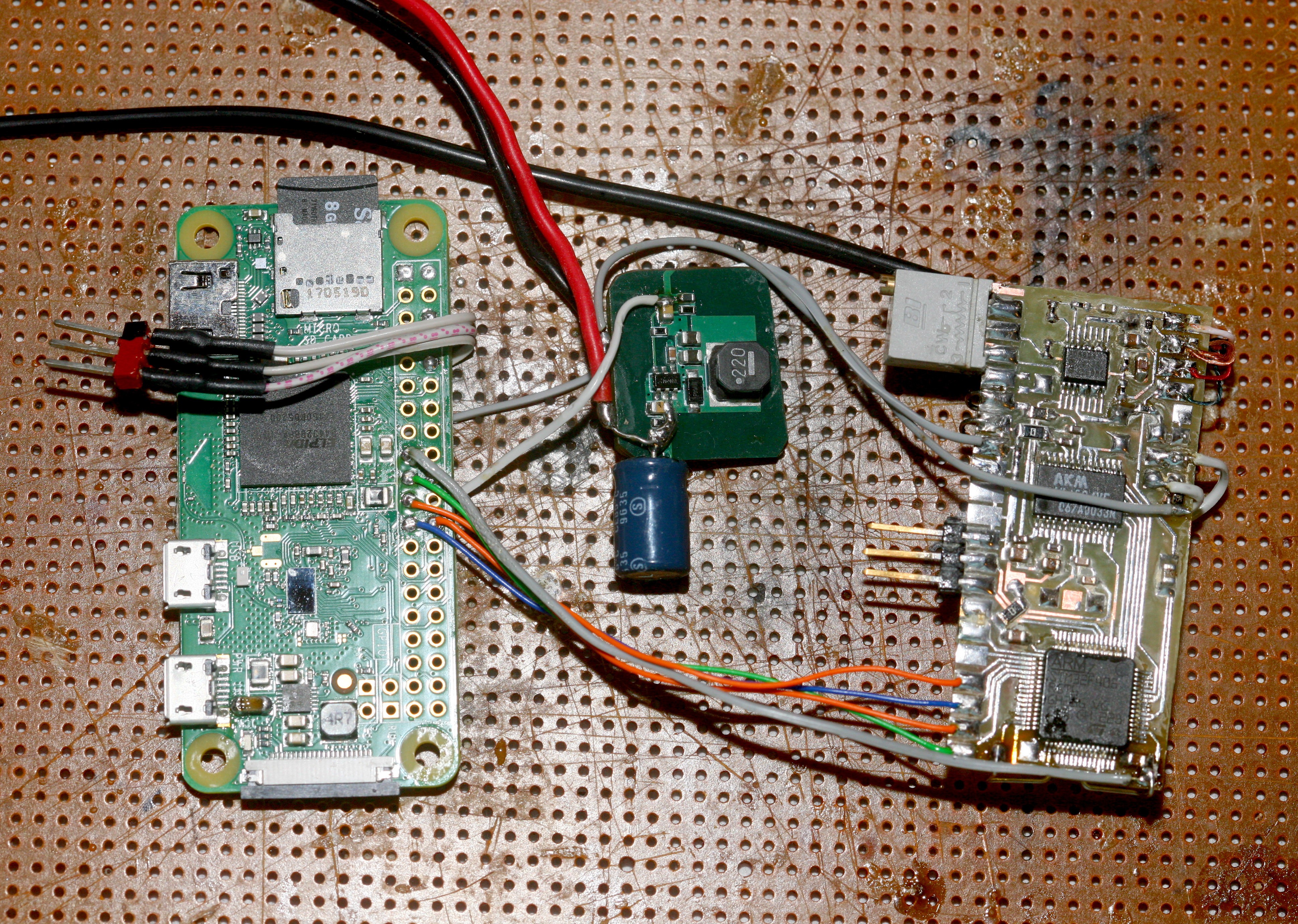
The scene with the final converter placement:
![]()
-
Version 2
12/25/2017 at 06:43 • 0 comments![]()
![]()
![]()
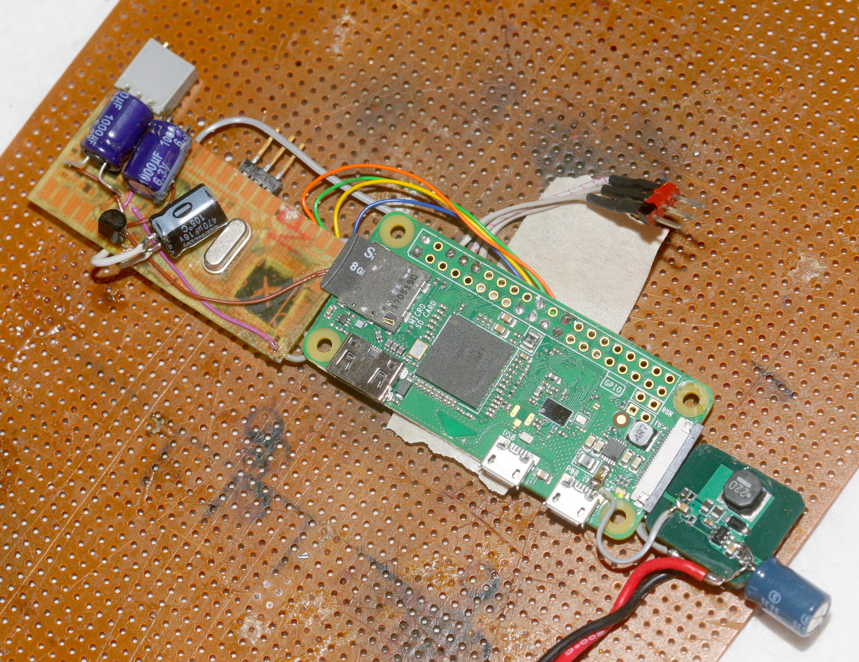
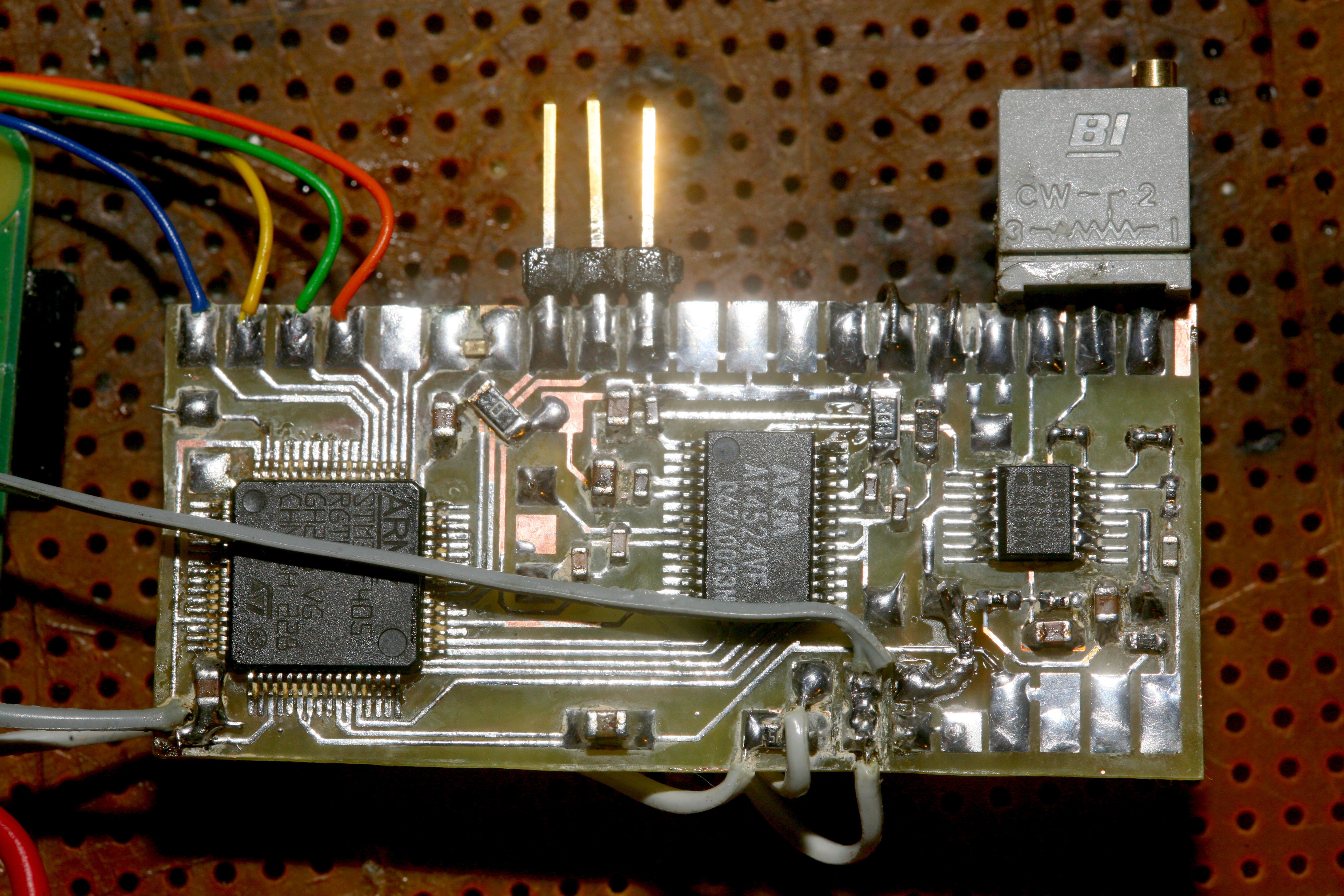
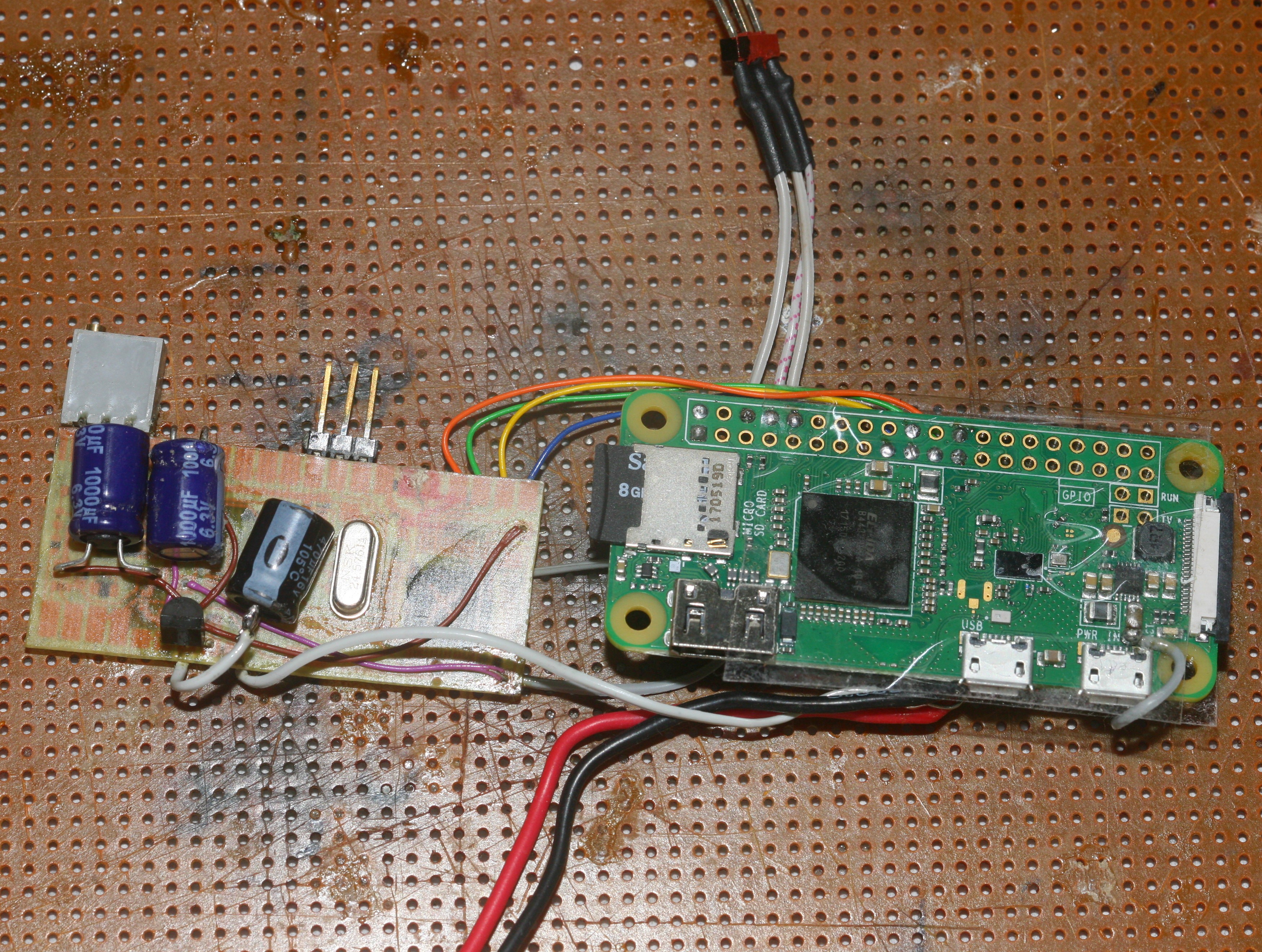
Version 2 immediately started with bodges & etching defects. Despite this, it ended up surprisingly clean. Got all the electrolytics & through holes on the bottom. Noted that the rainbow wrapping wire has insulation which melts extremely easily.
Unfortunately, the Metcal was unsuitable for drag soldering the chips in. Had to break out the Hakko. The Metcal may require a lower temperature, which requires ordering a new $30 tip & waiting a couple weeks. Its only advantage is the extremely fine point tips which actually heat up, unlike the fine pointed Hakko tips. Not sure inductive heating is necessary for getting heat.
The new board worked flawlessly on powerup & revealed new discoveries. WIFI at 5dbm doesn't work when the PI is upside down. The preamp is actually noisier at low frequencies when right side up. This might be from the table grounding something. The noise was unchanged from the dead bug circuit. With the gain at 100x, it only got 10 bits.
![]()
Tried cleaning flux from the preamp under the microscope, to no effect. The preamp would be quieter with metal film resistors. A test with the preamp disabled gave twice the noise of the dead bug circuit. It's now 13 bits & picking up switching noise. Moving the 8V to 5V converter under the PI produced the switching noise.
![]()
The AK4524 can actually take differential inputs if both converters are used. This got it up to 15 bits, but the extra space required to hook up another op amp & the noise from the op amp defeated it.
This noise testing is a bit academic, since the headset is going to obliterate the noise floor.
-
Downgrading to 48khz 16 bits
12/23/2017 at 04:38 • 0 commentsStepped the samplerate down to 48khz & averaged the 2 channels. This gave 14.5 bits, based on the peaks in the waveform. A true signal to noise ratio would use the RMS of the waveform, which might be slightly lower. Note that connecting the serial dongle to the STM32 adds RF noise.
Doing some basic calculations with the mighty PCM4222's datasheet showed even it only has a hair more than 17.5 real bits, with the figure degrading as it rises in samplerate.
The same calculations with the CM109 show it only has 12.5 bits, so no reasonably priced commercial product is going to do better than a home made board. Unfortunately, the STM32's built in 12 bit ADC would probably only give 10 bits.
If WIFI is turned off with the rfkill command, it can run on a common power supply without degrading the noise.
Powering the 78LS05 through a 5R & 470uF, with all the digital downsampling actually knocked the RF noise to a useful level. Any R above or below 5 increased the RF noise. There's a strange attraction between these active regulators & 5 ohms.
The WIFI power can also be changed with iwconfig wlan0 txpower commands. The effect on the waveform is dramatic at 1/262144 per pixel. 5dBm seems to be the limit before the noise becomes detectable.
![]()
The PI defaults to 31dBm which officially is 1 whole Watt. It actually works at txpower 0 which is 1mW. The effect on the waveform is from power consumption more than emissions, when the boards are spread out. When stacked, the emissions at even 10dBm obliterate the waveform. The BCM4343 indeed is rated for maximum consumption of 1W but maximum transmitter output of only 20dBm.
![]()
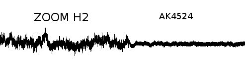
Finally captured some audio on the Zoom H2 with a 10k test input & compared it to the AK4524 test setup with 5dBm wifi.
![]()
Cable length was longer with the zoom, it had more input stages, but its gain was at minimum, which should have given the lowest possible noise. This ages old benchmark for superior audio was still a bit noisier than the dead bug circuit.
Ideally, there would be a way to control it without any radio. Wireless control from a phone is essential. A phone dongle for IR communication would be clunky but viable. Eliminating WIFI would allow the PI & a lot of components to be eliminated. The PI makes it bigger than a Zoom H1, but is a quick & dirty solution which can be dropped into a Zoom replacement.
-
Power supply filtering 2
12/22/2017 at 07:14 • 0 comments![]()
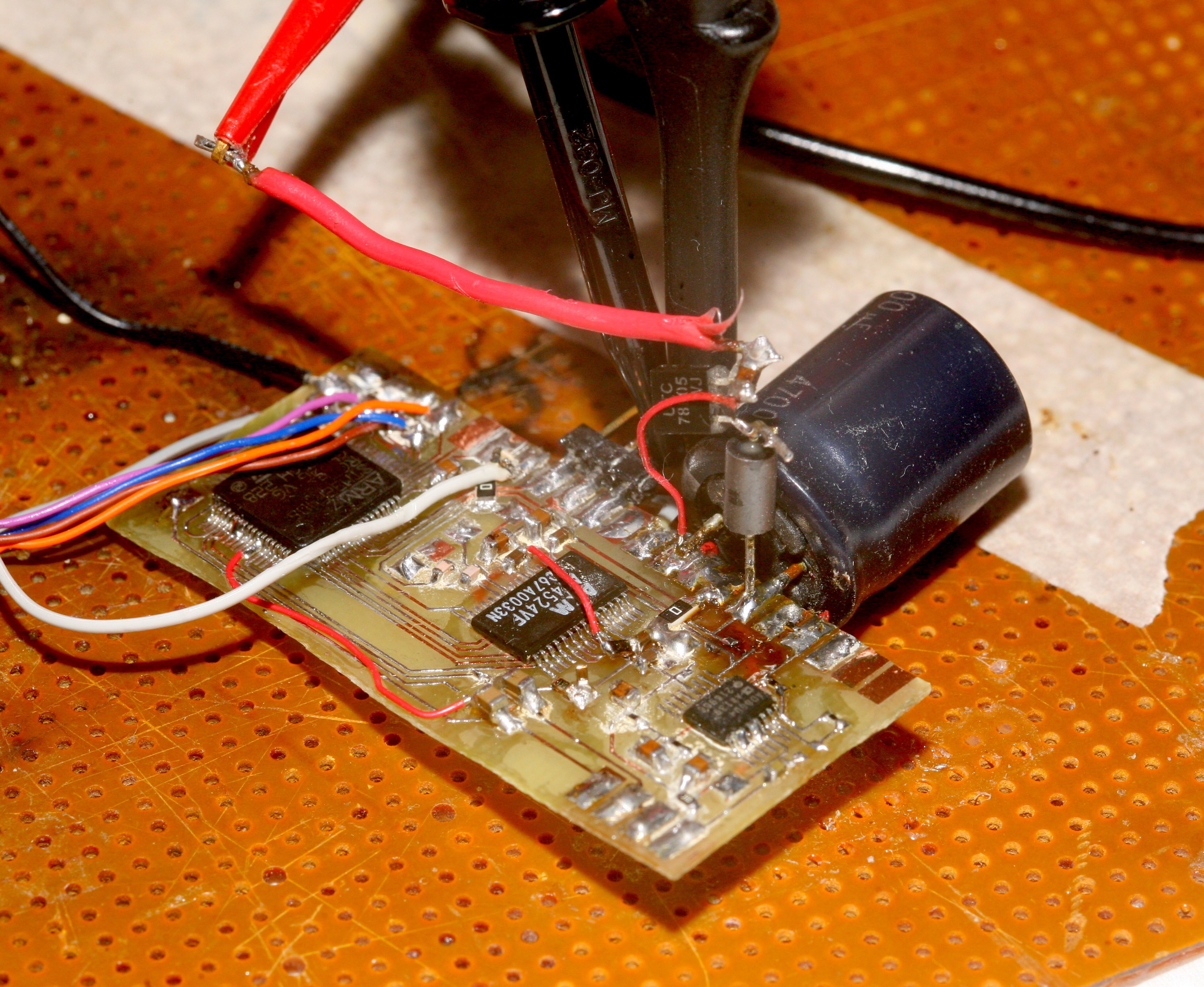
After ordering some CM109 based sound cards on the slow boat from China, the focus turned to minimizing the noise in whatever form factor it took, for future applications. Used the datasheet design for the AK4524 with an extra 4700uF, 5V regulator, RF choke, & power from an isolated bench supply. Also soldered a 10k chip resistor to the input, instead of the pot. It was a marvel of dead bug soldering.
That yielded 14 bits of precision. The 4700uF squeezed in a fraction of a 15th bit. Running it on the rated 5V instead of 3.3V definitely reduced the noise. There's some active power filtering inside the AK4524. Using too much or too little input resistance hurt it. Who knows how much of the noise is from the 10k as the analog source. Shorting it to ground produces all 0. There aren't many low impedance low noise sources.
The quest for the last 10 bits led to this nugget of information
https://www.edn.com/electronics-blogs/bakers-best/4314743/SNR-in-ADCs-Where-did-all-the-bits-go-
written by the same Bonnie Baker you'll find in the famous TI video
Then, there's an equation which translates the SNR to the effective number of bits.
https://en.wikipedia.org/wiki/Effective_number_of_bits
The AK4524 has 88dB on its datasheet for its most conservative SNR. ( 88 - 1.76 ) / 6.02 = 14
So basically, it only has 14 real bits of precision.
-
SPI between the raspberry PI & STM32
12/21/2017 at 04:37 • 0 commentsTransferring audio to the PI over SPI went relatively smoothly. 16Mhz over single ended SPI wires of 5cm worked.
On the PI, SPI only works in master mode. SPI initialization is the same as it was 5 years ago & looks like:
#define CHANNEL 0
#define SPI_BUFSIZE 2048

unsigned char buffer[SPI_BUFSIZE];

int fd = wiringPiSPISetup(CHANNEL, 16000000);
Sending a single packet on MOSI while receiving a packet on MISO:
wiringPiSPIDataRW(CHANNEL, buffer, SPI_BUFSIZE);
On the STM32F405, it starts with initializing the SPI driver for slave mode:
GPIO_InitTypeDef GPIO_InitStructure;
RCC_AHB1PeriphClockCmd(RCC_AHB1Periph_DMA1, ENABLE);
RCC_APB1PeriphClockCmd(RCC_APB1Periph_SPI3, ENABLE);
// SS
GPIO_PinAFConfig(GPIOA, GPIO_PinSource15, GPIO_AF_SPI3);
// SCK
GPIO_PinAFConfig(GPIOC, GPIO_PinSource10, GPIO_AF_SPI3);
// MISO
GPIO_PinAFConfig(GPIOC, GPIO_PinSource11, GPIO_AF_SPI3);
// MOSI
GPIO_PinAFConfig(GPIOC, GPIO_PinSource12, GPIO_AF_SPI3);

GPIO_InitStructure.GPIO_Mode = GPIO_Mode_AF;
GPIO_InitStructure.GPIO_Speed = GPIO_Speed_50MHz;
GPIO_InitStructure.GPIO_OType = GPIO_OType_PP;
GPIO_InitStructure.GPIO_PuPd  = GPIO_PuPd_DOWN;

GPIO_InitStructure.GPIO_Pin = GPIO_Pin_10 | GPIO_Pin_11 | GPIO_Pin_12;
GPIO_Init(GPIOC, &GPIO_InitStructure);

GPIO_InitStructure.GPIO_OType = GPIO_OType_OD;
GPIO_InitStructure.GPIO_PuPd  = GPIO_PuPd_UP;
GPIO_InitStructure.GPIO_Pin = GPIO_Pin_15;
GPIO_Init(GPIOA, &GPIO_InitStructure);

SPI_I2S_DeInit(SPI3);

SPI_InitTypeDef SPI_InitStructure;
SPI_InitStructure.SPI_Direction = SPI_Direction_2Lines_FullDuplex;
SPI_InitStructure.SPI_DataSize = SPI_DataSize_8b;
SPI_InitStructure.SPI_CPOL = SPI_CPOL_Low;
SPI_InitStructure.SPI_CPHA = SPI_CPHA_1Edge;
SPI_InitStructure.SPI_NSS = SPI_NSS_Hard;
SPI_InitStructure.SPI_BaudRatePrescaler = SPI_BaudRatePrescaler_16;
// SPI_InitStructure.SPI_BaudRatePrescaler = SPI_BaudRatePrescaler_32;
// SPI_InitStructure.SPI_BaudRatePrescaler = SPI_BaudRatePrescaler_256;
SPI_InitStructure.SPI_FirstBit = SPI_FirstBit_MSB;
SPI_InitStructure.SPI_CRCPolynomial = 7;

SPI_InitStructure.SPI_Mode = SPI_Mode_Slave;
SPI_InitStructure.SPI_NSS = SPI_NSS_Hard;
SPI_I2S_DeInit(SPI3);
SPI_Init(SPI3, &SPI_InitStructure);
Then, every packet needs 2 DMA transfers to be initialized for the 2 data directions:
#define DMA_RX_STREAM DMA1_Stream2
#define DMA_TX_STREAM DMA1_Stream5

#define SPI_BUFSIZE 2048
uint8_t rx_buffer[SPI_BUFSIZE];
uint8_t tx_buffer[SPI_BUFSIZE];

DMA_InitTypeDef DMA_InitStructure;
// enable receive DMA
  DMA_InitStructure.DMA_Channel = DMA_Channel_0;
  DMA_InitStructure.DMA_PeripheralBaseAddr = (uint32_t)&SPI3->DR;
DMA_InitStructure.DMA_Memory0BaseAddr = (uint32_t)rx_buffer;
DMA_InitStructure.DMA_DIR = DMA_DIR_PeripheralToMemory;
DMA_InitStructure.DMA_BufferSize = SPI_BUFSIZE;
DMA_InitStructure.DMA_PeripheralInc = DMA_PeripheralInc_Disable;
DMA_InitStructure.DMA_MemoryInc = DMA_MemoryInc_Enable;
DMA_InitStructure.DMA_PeripheralDataSize = DMA_PeripheralDataSize_Byte;
DMA_InitStructure.DMA_MemoryDataSize = DMA_MemoryDataSize_Byte;
DMA_InitStructure.DMA_Mode = DMA_Mode_Normal;
DMA_InitStructure.DMA_Priority = DMA_Priority_High;
  DMA_InitStructure.DMA_FIFOMode = DMA_FIFOMode_Enable;
  DMA_InitStructure.DMA_FIFOThreshold = DMA_FIFOThreshold_Full;
  DMA_InitStructure.DMA_MemoryBurst = DMA_MemoryBurst_Single;
  DMA_InitStructure.DMA_PeripheralBurst = DMA_PeripheralBurst_Single;

DMA_DeInit(DMA_RX_STREAM);
  DMA_Init(DMA_RX_STREAM, &DMA_InitStructure);
SPI_I2S_DMACmd(SPI3, SPI_I2S_DMAReq_Rx, ENABLE);


// enable the transmit DMA
DMA_DeInit(DMA_TX_STREAM);

DMA_InitStructure.DMA_Memory0BaseAddr = (uint32_t)tx_buffer;

DMA_InitStructure.DMA_DIR = DMA_DIR_MemoryToPeripheral;
DMA_Init(DMA_TX_STREAM, &DMA_InitStructure);
SPI_I2S_DMACmd(SPI3, SPI_I2S_DMAReq_Tx, ENABLE);

SPI_Cmd(SPI3, ENABLE);
DMA_Cmd(DMA_RX_STREAM, ENABLE);
DMA_Cmd(DMA_TX_STREAM, ENABLE);
The STM32 has to wait for DMA_RX_STREAM->NDTR to be 0 to know the packet has been transferred & it's time to reinitialize the 2 DMA transfers. It can also be done by polling (SPI3->SR & SPI_FLAG_RXNE), then reading & writing bytes to SPI3->DR. This has all probably been abstracted into Arduino for STM32.
It was finally possible to view the data in an audio editor. Amplifying it 256x revealed the lowest 16 bits & it was soul crushing noise.
Unfortunately, running SPI & writing to the SD card added a lot of noise. Disabled the preamp & just ran the ADC. It had the wifi pulses & lots of noise from SPI. It should be noted the ADC input without the preamp has to be grounded through a 10k. Leaving it open makes it an antenna & short circuiting it causes the ADC to send all 0.
![]()
What was inaudible on the phones was equivalent to an 8 bit ADC in the audio editor. Every Y pixel is equivalent to 1/65536. Going back to the dedicated 4.2V battery over a 17R & recording the ground got the noise slightly lower.
![]()
That's probably 10 bit precision. You're not going to get even 16 bit precision in this form factor, right next to the PI, with the wifi going.
![]()
Spreading it out got it up to 11 bits with no wifi pulsing.
The ultimate vlogging mic
Recording the best headset audio in a portable form factor
 lion mclionhead
