Andrew Mayhall
-
Operation of magnetic stirrer
12/19/2017 at 20:01 • 0 commentsIn my last project log entry I walked though the assembly and completion of the magnetic stirrer for the fluidized bed.
In this entry I will share some sort clips of the operation of the magnetic stirrer and over the next coming days I will hopefully continue to update this project with the process of powder coating using this fluidizer.
Thanks again for following along!
-
Upgrading the Fludizer
12/16/2017 at 01:46 • 0 commentsIn my last project log entry I wrote about the various categories of particle fluids and the need for mechanical agitation during fluidizing for specific types of powdered materials. Additionally I walked through the designs of the magnetic stirrer that I would be implementing as well as how it would function over all. This entry will show the completed stirrer mechanism and the assembly process to make it functional.
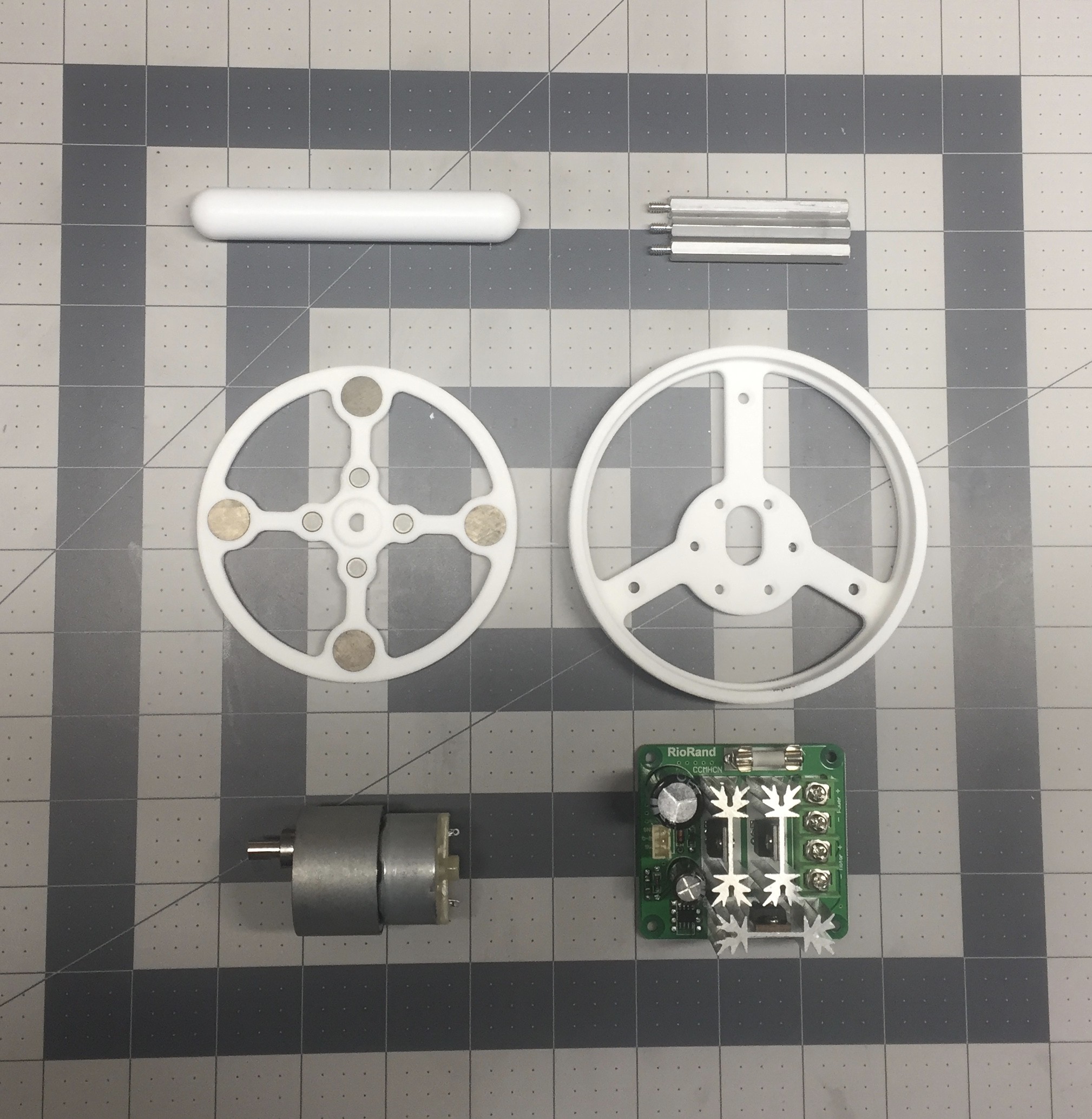
The major components that make up the stirrer are pictured below. Everything besides the 3D printed mounting bracket and the magnetic spinner ring are stock parts that can be sourced through McMaster Carr and Amazon. A detailed list of components is available for this project.
![]()
I had the two 3D printed parts made form SLS nylon through i.materialize. These can certainly be printed on any FDM machine if you have access to one. i.materialize offers a very quick turnaround time at competitive rates so it was just easier for me to order it and forget. If others are interested in building their own I have uploaded the STL files. I think these parts cost me around $60 including shipping.
I started the assembly by pressing the magnets into the recesses in the magnetic spinner making sure to match the same polls on each strut and to flip the polls on the opposing strut. Some super glue made sure the magnets were permanently attached.
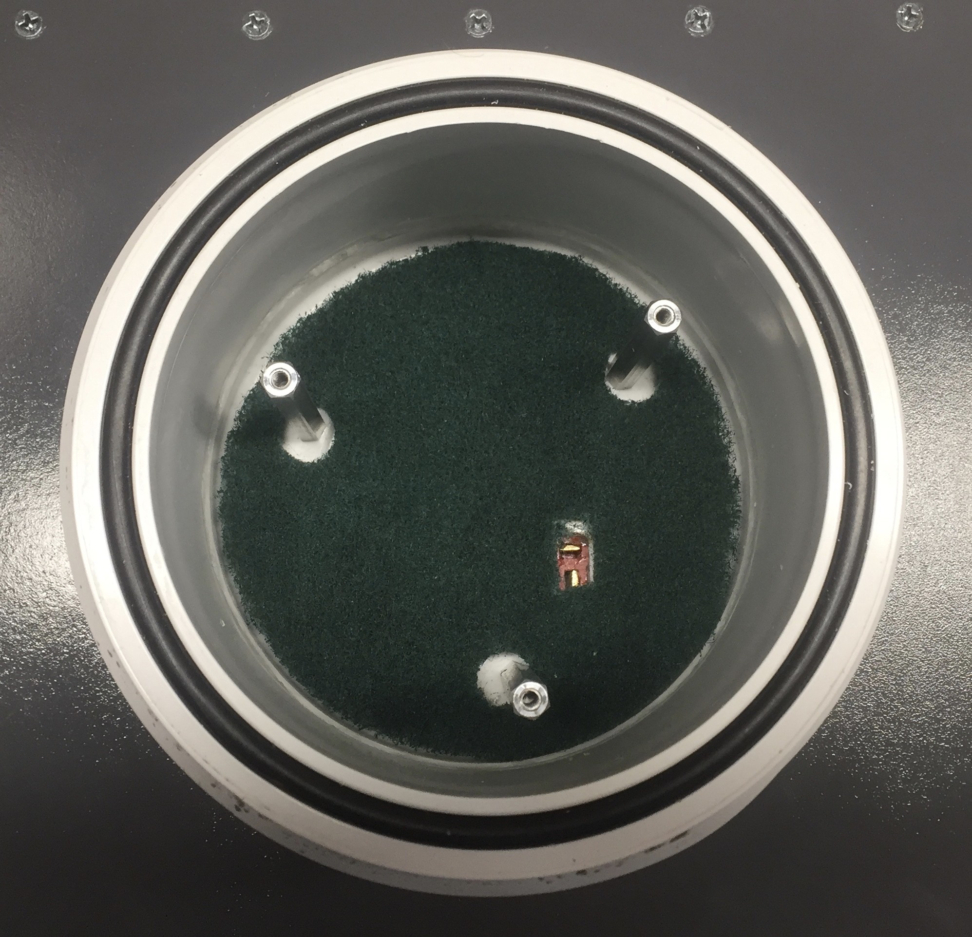
Next I shifted focus to installing the aluminum standoffs into the base of the fluidizer. I used the mounting bracket as a template to drill the tapped holes for the standoffs. At this time I also added a power connector by using a Dremel to shape a hole in the end of the PVC cap used to close off the bottom of the fluidizer.
![]()
The green material seen at the bottom of the fludizer base is a cut section of Scotch-Brite scouring pad. This will prevent silica beads from falling down into the 1/4" brass fitting used as the air inlet. I will talk more on this later.
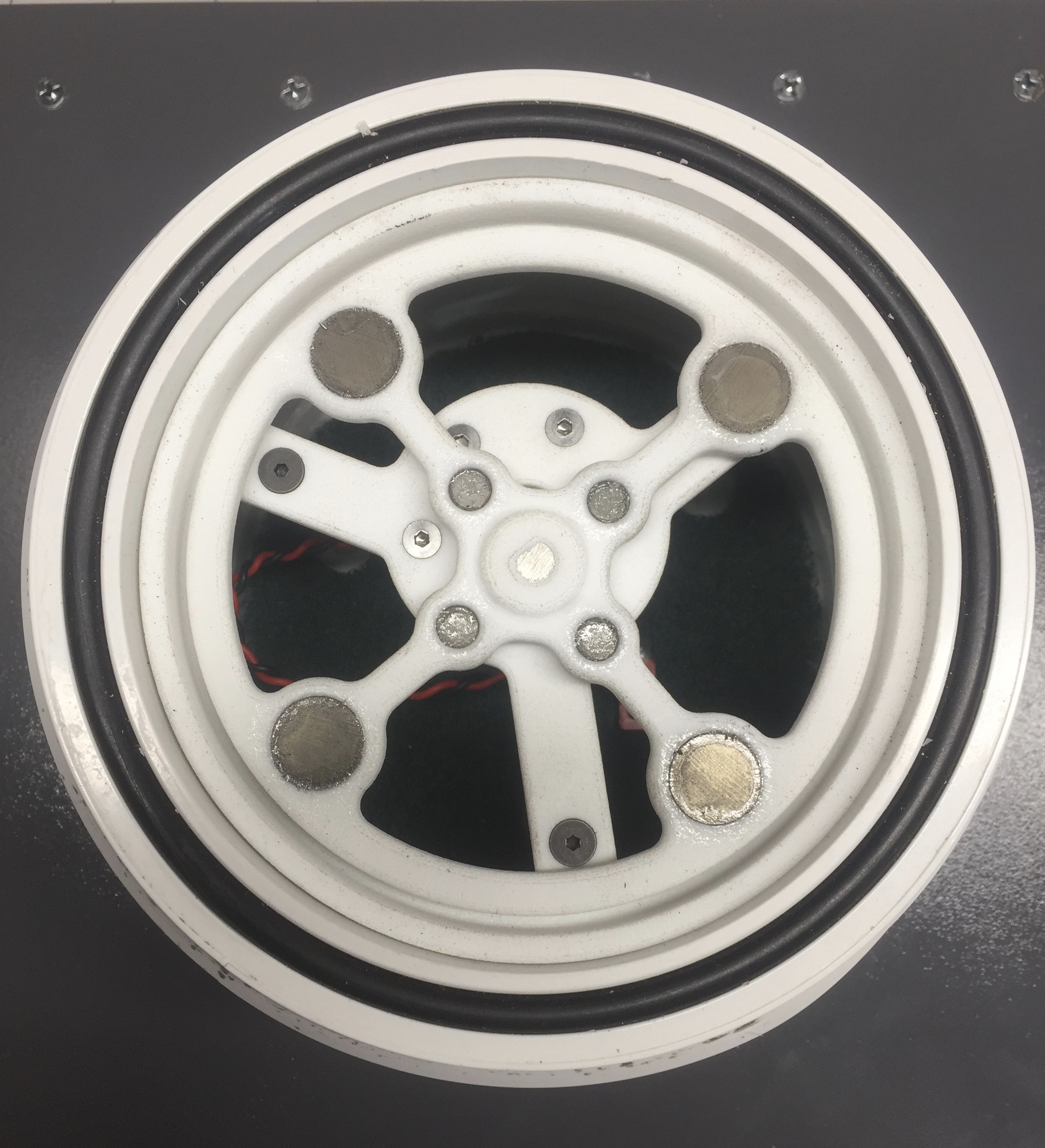
Overall assembly is pretty straight forward. Using the M3 fasteners I fixed the motor to the 3D printed mounting bracket. I connected the power to the motor and installed the mounting bracket on the standoffs using the 6-32 fasteners. Then it is as simple as pressing on the magnetic spinner ring.
![]()
Since this fluidizer uses air as its working gas humidity will play a big roll in how a particular powder will behave when fluidized. Especially for longer or continuous operations.
Powder coating material will form agglomerates when exposed to humidity. The best option would be to used a nitrogen supply form a welding tank to ensure the particle fluid will not change its properties over time. Since this fluidizer is relatively small and will only be run in short batches air should be okay. That being said it is important to try and stack the deck in your favor at all times!
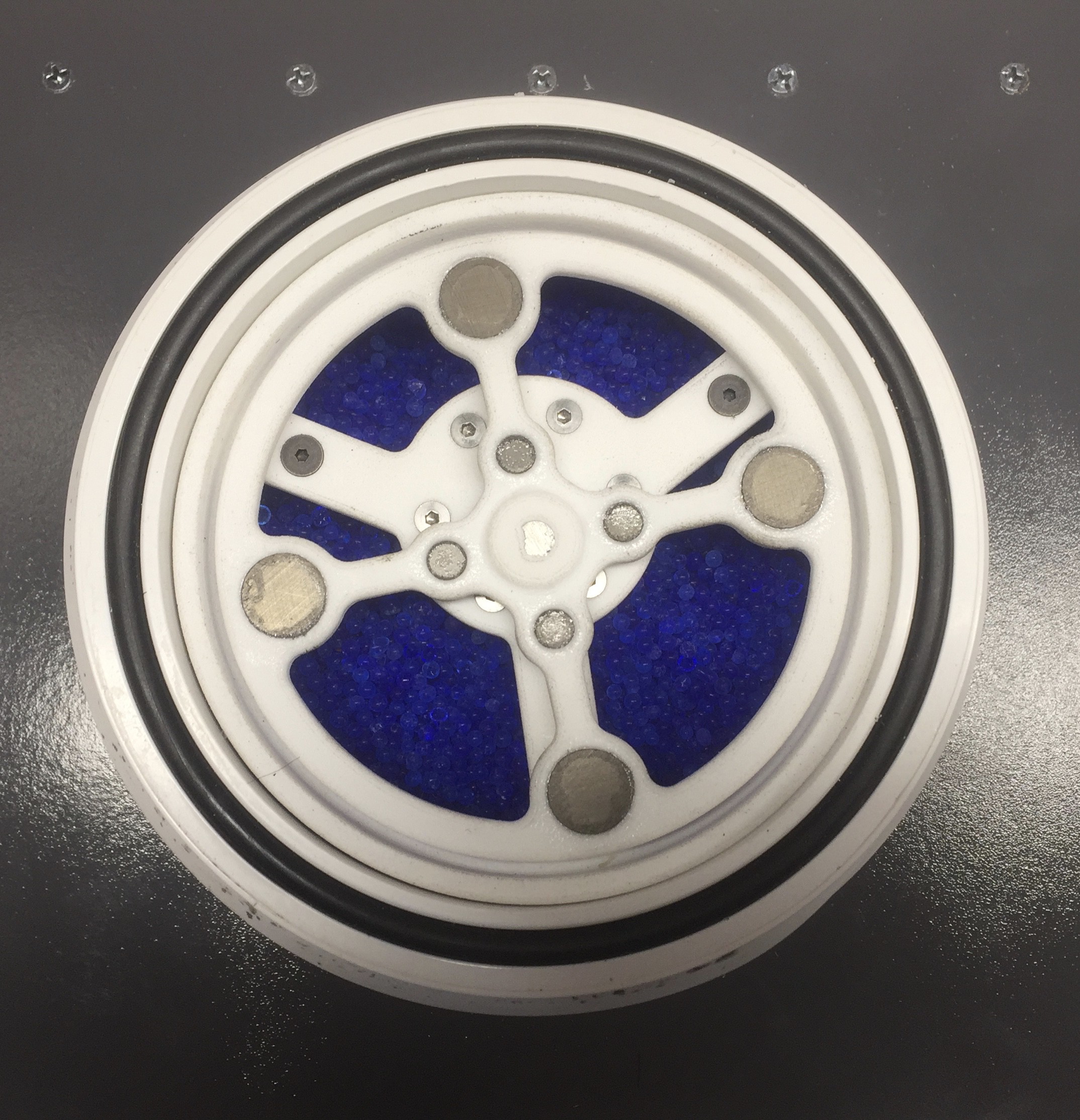
For this build I will be using indicating silica beads located in the base of the fluidizer to help absorb any moisture in the air supply. They likely won't help a ton but every little bit counts.
![]()
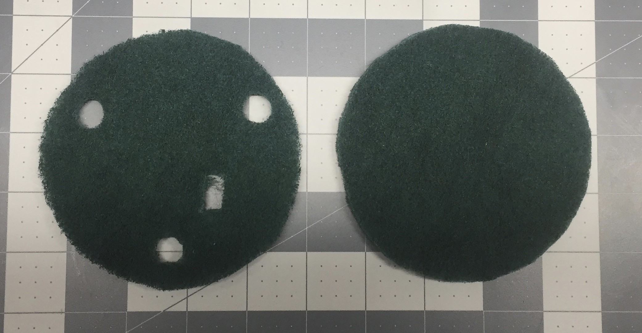
In order to keep the beads from clogging my air supply line I installed a cut section of Scotch-Brite scouring pad.
![]()
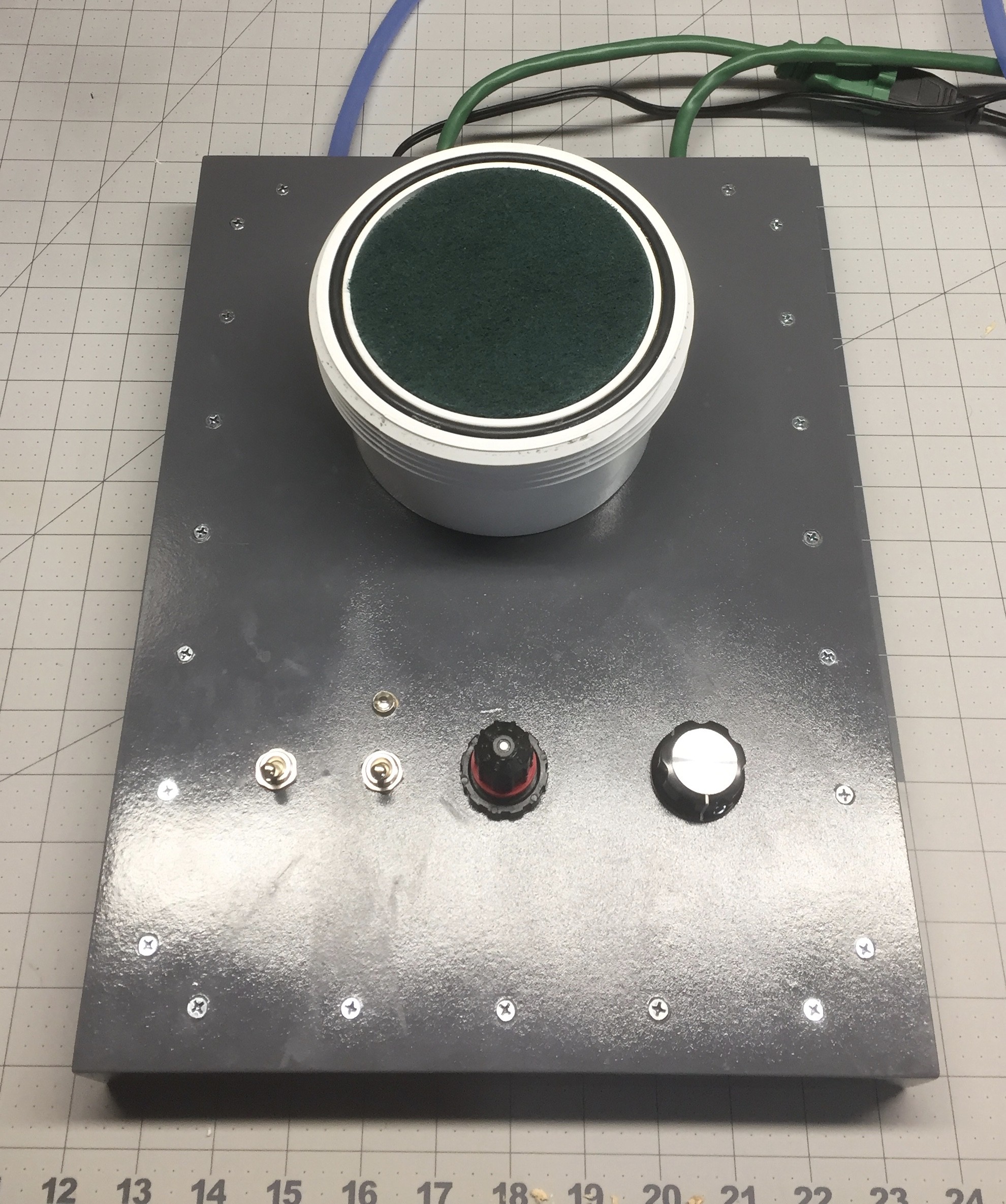
There are actually two pieces being used. One for the bottom which was show in place earlier. The other section actually sits on top of the magnetic spinner rig to provide support for the membrane when a stirrer bar is in place.
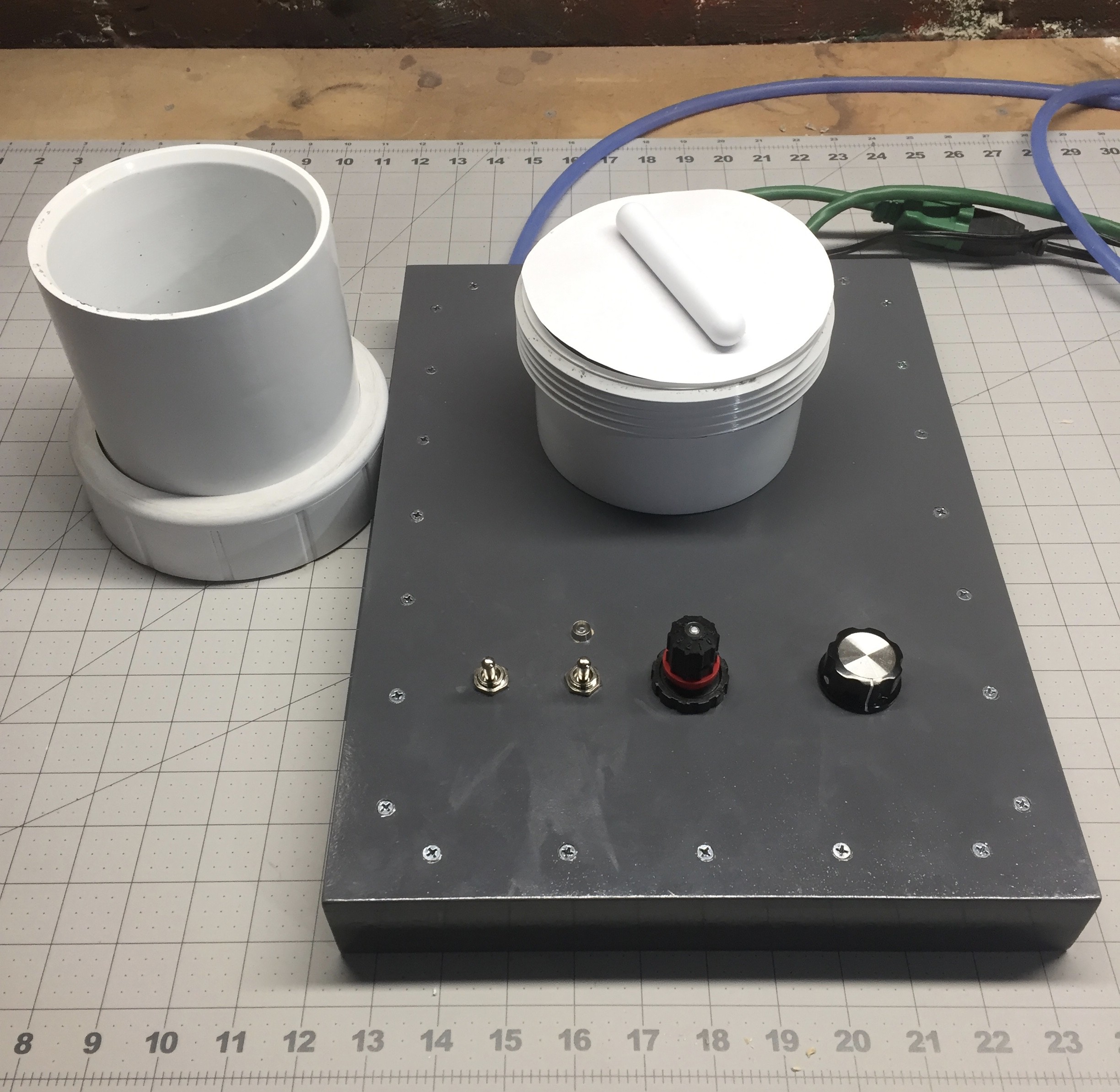
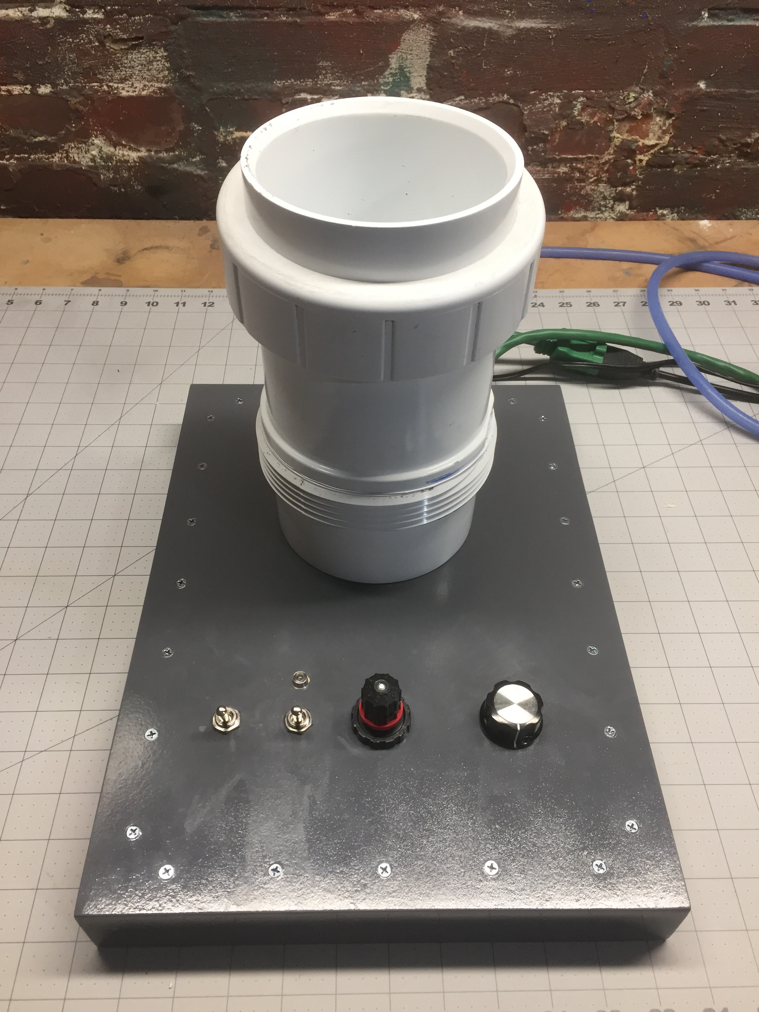
From here the upgrades are pretty much complete. I will show the rest of the assembly of the fluidizer below.
![]()
![]()
![]()
![]()
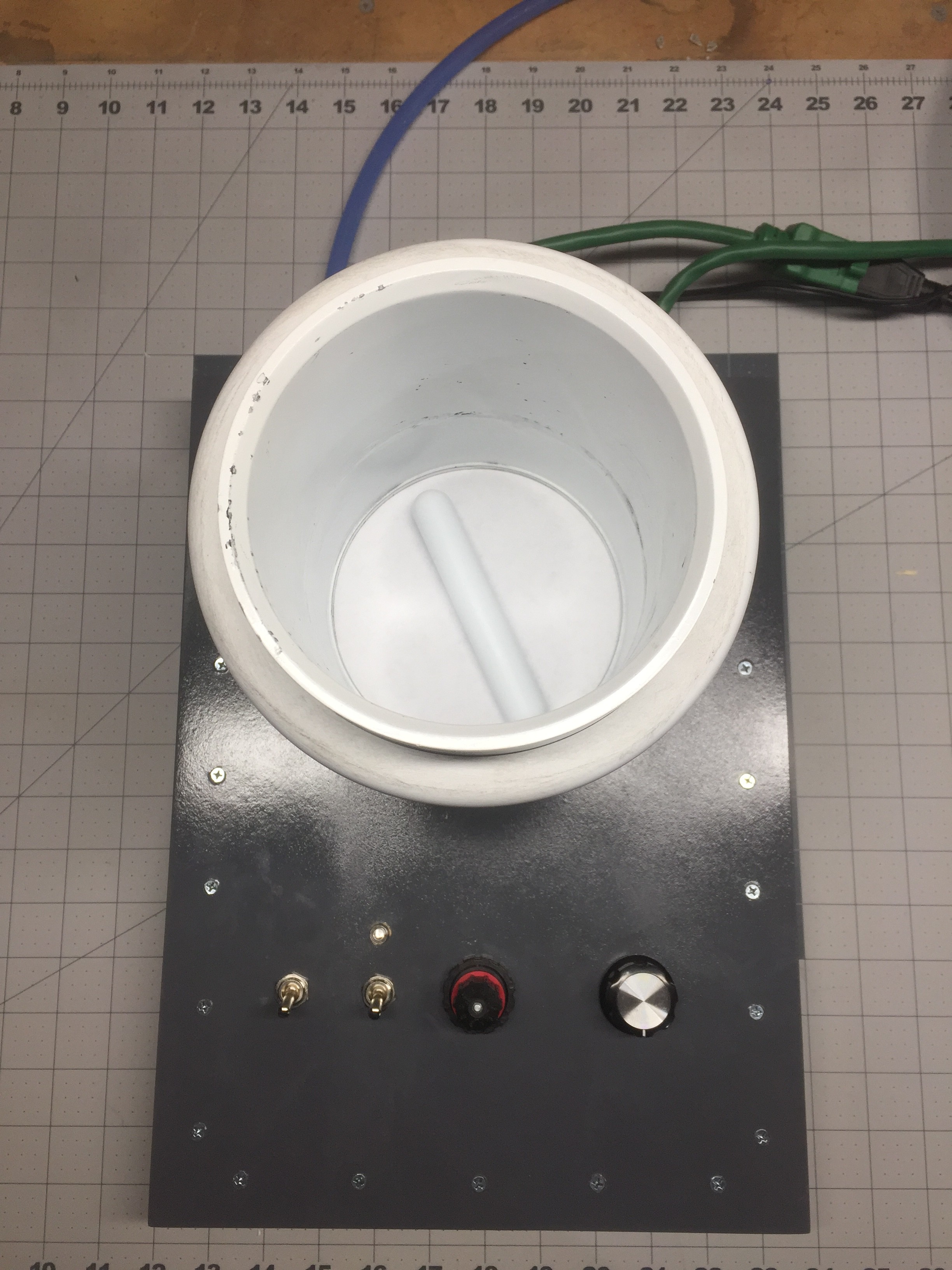
The control of the fluidizer is very simple. The left most switch turns on the air supply, the second switch turns on the magnetic stirrer. The center dial is a precision set flow valve for adjusting the air supply and the right dial is the speed control for the magnetic stirrer.
Overall the upgrade was a total success. I will be posting a few videos soon on the operation and various characteristics of fluidizied powders so please watch for another log entry soon!
I hope you enjoyed following along!
-
Adding mechanical agitation
12/15/2017 at 01:58 • 0 commentsWhen I started this project I knew at some point I would want to add a form of mechanical agitation or stirring action to the fluidized material for better part coverage and easier fludization of the powder.
![]()
This log I will go into detail of my plans to build a magnetic stirring system into the base of the fluidizer and the reasoning behind the addition. First, I will provide some more background on particle fluids though!
Fluidizers work under the principle that a flow of a gas up through a powdered material will suspend the mass of the individual particles within the powder material in the flow of gas causing these particles to behave much like the molecules of a fluid. Not all powders are alike and like different fluids each powder will behave differently depending on its particle properties.
In industry, the exact process of fluidizing particles begins by classifying them into categories or groups according to their size and ease of fluidization. Professor D. Geldart is responsible for creating these groups and they have largely remained unchanged since 1973. These groups provide a good guideline for how the particles will behave when fluidized.
Group A: Particle size is between 30 and 100 µm, and the particle density is typically less than 1.4g/cm3. Particles in group A are known as "Aerate-able" showing a significant expansion of the material before fluidization beings.
Group B: Particle size is between 40 and 500 µm and the particle density between 1.4-4g/cm3. Particles in this group are known for "Bubbling" creating larger bubbles of gas and less overall mixing of the particles.
Group C: Is the most difficult to achieve fluidization at a size of 1 to 30 µm. Particle density can vary widely as particles in this group are known as "Cohesive". Fluidization is strongly affected by inter-particle forces with the formation agglomerates and channeling of the gas stream. Mechanical agitation as well as low humidity gas can be used to facilitate easier fluidization.
Group D: Particles are above 600 µm and can range up to 100mm typically possess high particle densities. Fluidization requires high fluid velocities and are typically considered abrasive. Particles in group D are known as "spout-able" for large bubbles that form and move very slowly through the fluid with an overall slow percolation of gas though the particles.
Fortunately for us home gamers, a lot of powdered materials that would be used in a system like this will fall into group A. Providing an easy fluidization and a pleasant operating experience.
One important and rather interesting discovery has been when using higher quality powder coatings in the fluidizer, the stronger resemblance of a group C particle fluid. Especially primary colors, blacks, and matte finishes. This is due to the much smaller particle size and the base material having more inter-particle interactions. Most powder coats are made from polyester plastic but there tends to be a variation of which "type" of polyester is used as well as any additives for finishes, textures, or colors. Higher quality powders also tend to be finer grain size for more uniform finishes.
As Mr. Geldart mentioned in his group C classification, fluidization is difficult and mechanical agitation is usually required. This means getting properly fluidized powder for these finishes can be; and usually is; a pain.
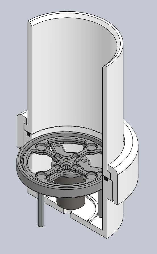
My solution was to design and 3D print a magnetic stirrer that will fit into the base of the fluidizier. Its main goal was to slowly agitate the lower layer of the powder material during fluidization to break up any agglomerates and reduce the tendency to form channels. Below you can see an isolated version of the stirrer apparatus.
![]()
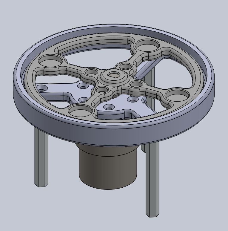
At the heart of the operation is a 60RPM gear motor rated for 12v nominal. I happen to be running this motor around 18v with no issues for 90 or so max RPM. I could have sourced a 100RPM motor but the ones available were a bit larger than the 60RPM version so it would be difficult to fit in something I already have built. An important consideration is when agitating a cohesive fluid, speed isn't the solution but it helps to have a decent range available for different particle fluids!
The motor is attached to a mounting ring that centers the output shaft in the PVC union. Standoffs fix the mount to the end cap this way if I need to replace anything I can take the whole assembly out. The outer ring of the mount is sized slightly smaller that the inner diameter of a 4" PVC fitting meaning it can be friction fit or glued in place if desired.
![]()
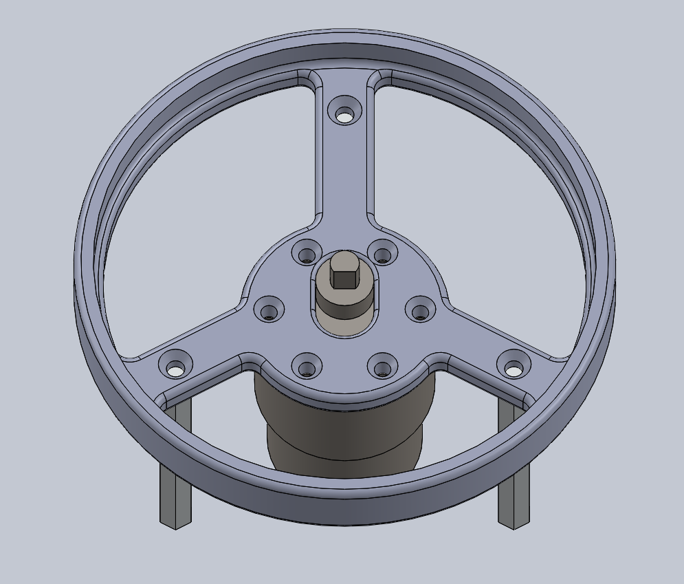
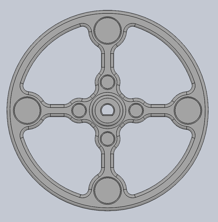
Fixed to the output shaft of the motor is the magnetic ring. The motor comes with a D shaft and I had the hub printed with a slightly smaller profile than the shaft and tapped it into place. This design could be simplified but it was nice to have the ring around the outside for stability and the additional magnets.
![]()
Speaking of magnets! There are 8 magnets in total. 4: 1/2" and 4: 1/8" N52 grade. Since the stirrer bar would be about 8mm away I wanted to ensure good coupling plus I had these particular magnets on hand. I wasn't sure which size stirrer I would use so the inner magnets allow me to use smaller stirrers while the outer ones are well suited for a 4" stirrer bar.
Lastly, I decided it would be a good idea to add PWM control to the motor. I just sourced an off-the-shelf motor controller form Amazon that fit my requirements. I will show everything else including operational videos and assembly pictures in more detail in a later log.
Thanks for following along so far! Hopefully you will stick around to see it completed!
Well when I get around to showing everyone its complete that is...
Fluidized Bed for Powder Coating
Powdered fluidizer for coating parts in various materials such as glitter, velvet, powder coat, powder sugar, etc.