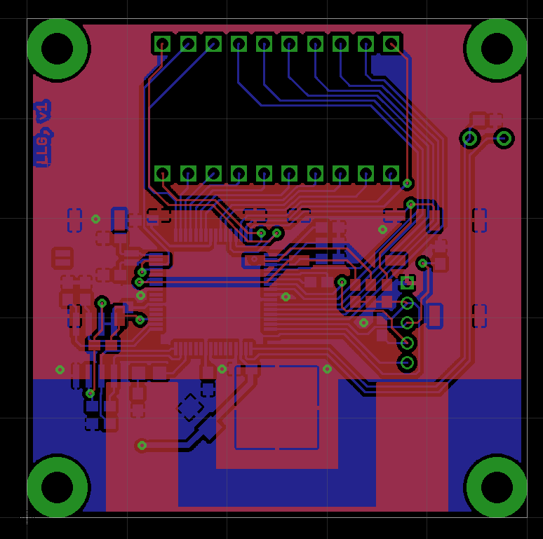
While dumb loggers are doing their job, I designed LCB for final LLG PCB. Concept was clear - all I need is CR2032 (obviously), small bare-glass LCD, appropriate MCU with LCD driver and a few kB of RAM, storage, photosensor and a few buttons. This all should form PCB for small portable device, capable of taking measurement of incoming light, calculating its own position and logging/displaying it on LCD.
I opted for PIC24FJ128GA306 as brainbox for this one. According to datasheet I should be able to achieve consumption 0,33uA for sleep mode, 0,4uA for RTCC with 32kHz oscillator, and 0,8uA for LCD driver with 1/3 bias plus 1uA for resistor ladder, together roughly 2,5uA for device doing its job, though mostly sleeping and displaying stuff on the LCD. With LCD off, the figure should be around 0,7uA.
The logger with wake up every few seconds to take measurements, let's say it's every 10s. If measurement will take under 10ms (it definitely will) and will take under 1mA, the duty cycle ratio will be less than 0,1%, meaning less than 1uA of average current consumption. Let's consider it is 0,5uA, I can expect battery life roughly 9 years for mode with LCD constantly on and displaying stuff and 23 years with LCD off, way above shelf life of battery.
I had more devices in consideration at this point - I thought of PIC18F67K90, but the PIC24 part should have somehow lower current consumption. I considered MSP430 devices too, but somehow I couldn't find devices with 4 or 8 kB of RAM, LCD driver and sane package (TQFP48/64). STM32L looked promising, but after not exactly short digesting of their datasheet I learned their current consumption in this application would be higher than that of PIC24.
For LCD I opted for small 8-position seven-segment LCD, DE-188. It has four backplanes, but the driver in PIC should be able to drive eight of them, so I'm set. I was careful to select model with 3V driving voltage.
For dumb loggers I chose for 24LC64 EEPROM as storage, one of reasons being I had a lot of them. I2C devices are not particularly good for low-power applications. Open drain nature of communication lines means that the current flows for approximately 50% of communication duration. Interfaces like SPI are somehow better suited here, with totem-pole output, so I selected 25AA256 as storage device. It should have enough of capacity for a few years worth of logging, with simple upgrade path to higher capacity density.
For light sensor I'm not yet completely determined, but it looks like I'm going with LDR for now. The PCB design will allow using photoresistor too.
The rest of things was quite straightforward, buttons, some pull-ups, crystal, decoupling capacitors, with final PCB being 50x50mm (50mm equals to 1 and 62/64 of inch) yet being not exactly crowded.

Most of components and traces are on bottom side, with top side being populated by buttons, LCD, photo sensor and battery.
The contest deadline is in less than two weeks and most PCB houses here do have their offices closed up to early January due to holidays. Fortunately, friend of mine is able to produce double-sided PCBs with soldermask (no metalized vias, though) so this should save me. Let's see in next log in a few days.
 jaromir.sukuba
Discussions
Become a Hackaday.io Member
Create an account to leave a comment. Already have an account? Log In.
Does the PIC refresh the LCD in sleep?
Are you sure? yes | no
Yes, that is the 0,8uA of consumption - for LCD refresh.
Are you sure? yes | no
Nice, I need to play with an LCD-enabled PIC.
Are you sure? yes | no
@Ted Yapo To name a few different LCD enabled devices:
I have another CR2032 project with PIC16LF1939 I started for con cell contest (not published yet), driving 4-digit 7-segment LCD with four backplanes, initialization was something like touching 4 registers, I just went through datasheet and set them as needed - so it's quite simple and worked on first try, few minutes worth of work. When it comes to current consumption, these PIC16F1xxx do have significant differences between F and LF models due to enabled/disabled internal LDO, be careful when purchasing.
I considered to use PIC16LF19197 for LLG, but it wasn't available at the moment from any major distributor. Those newer PIC16F1xxx do have switchable internal LDO, but still, LF parts do have slightly lower consumption than F parts.
Years ago I made thermometer with PIC16F917, this is one of oldest LCD enabled PICs, now showing its age.
Are you sure? yes | no
I will check out those parts. I have had a project in mind for 15 years, and maybe the parts finally reached the level of performance required.
Are you sure? yes | no
@Ted Yapo I have measurement from real hardware- with PIC in sleep mode, internal RTC running from 32kHz crystal, LCD driver on, all segments off - 2,37uA; all segments on - 3,13uA. As per expectations.
Are you sure? yes | no
Those are pretty good numbers!
I started making a board around a PIC16LF19176 last night :-)
I assume the current will drop somewhat if I use the 31kHz LF osc for the LCD, since I don't need a RTC.
Are you sure? yes | no