 Christoph Tack
The trouble with telephone lines is they carry relatively small audio signals and high voltage ringing signals. If the circuitry is placed in parallel with the telephone line, it has to deal with the ringing voltage. At the same time, the circuit must be low-Z enough to inject audio signals.
The alternative option chosen here is to design circuitry that sits in series with the telephone line. The advantages are:
- No current consumption on hook.
- Easy way to feed electronics using a zener diode (only off-hook and in between DTMF-bursts).
- High ringing voltage is no longer an issue. The maximum voltage over the circuit is limited by the zener diode.
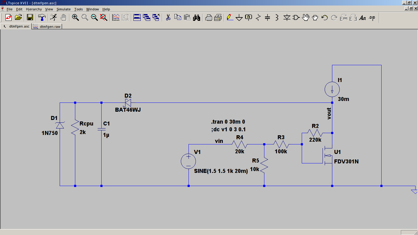
The SLIC provides a 30mA current loop, that's I1.
U1 is the variable load, modulated by the DTMF-source, U1. When the horn goes off-hook, the connected telephone closes the loop with a 300ohm resistor. The current through the loop will rise to 30mA. This causes the voltage over D1 to rise to 4.7V. The MCU will startup. U1 will start sinking considerable current. The rest of the current will be used to power the electronics. The DC-bias current through U1 can be set with R2 and R3. Check that during DTMF-transmitting, the output voltage (VOUT) doesn't exceed the zener voltage. The zener will limit the VOUT and distort the signal.
When transmitting DTMF, R4 and R5 set the amplitude of the DTMF-signal voltage on the current loop.
4.7nF caps will be added in parallel with R5 and to the base of U1 to filter the HF-noise of the PWM-output of the MCU.
Discussions
Become a Hackaday.io Member
Create an account to leave a comment. Already have an account? Log In.