Ben
Ben-
Been a while
06/11/2018 at 10:31 • 0 commentsIt's been a while since I last posted a log, a lot has changed.
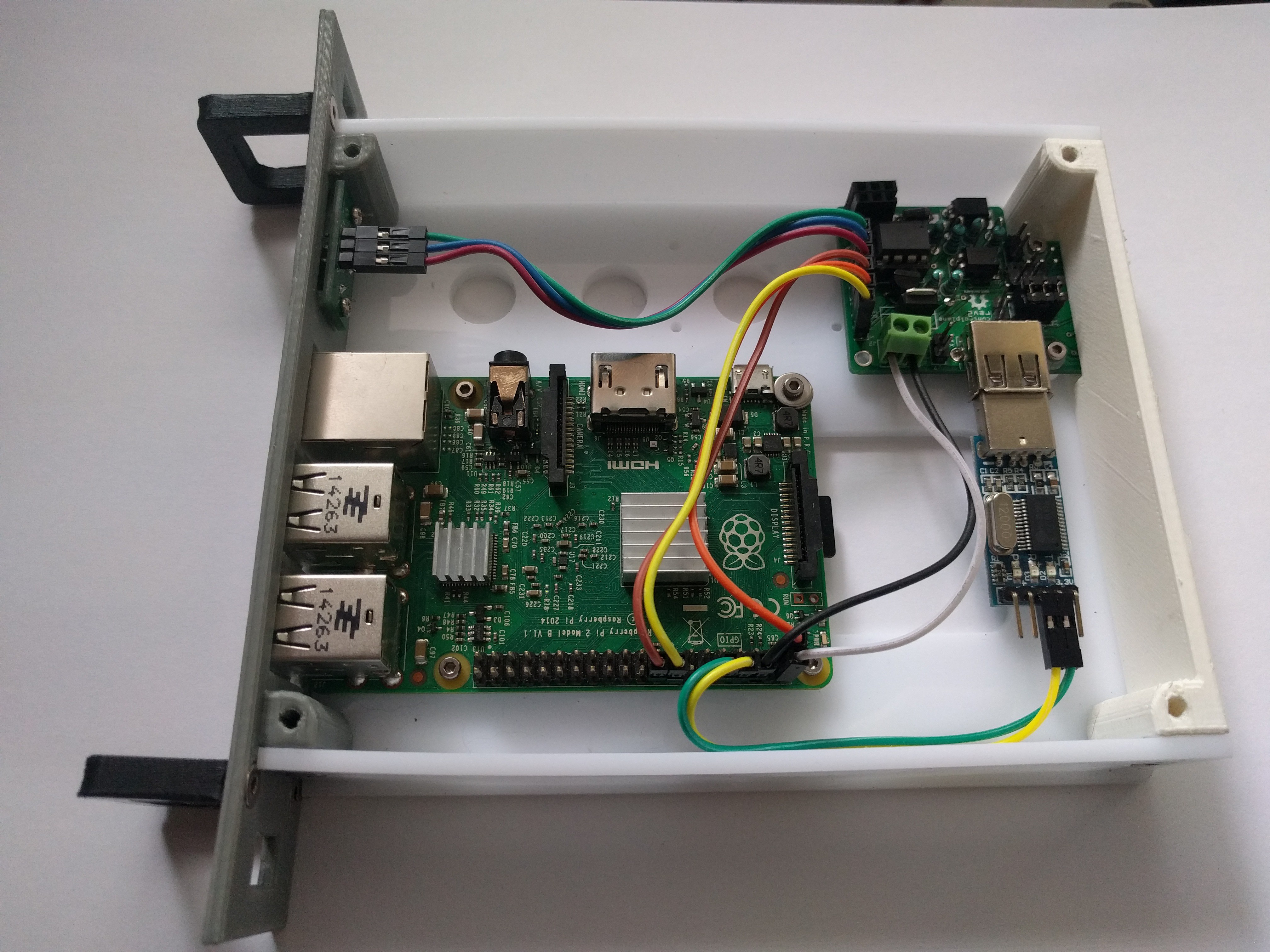
I've change the way that the backplane communicates to the main software. It now connects to a custom Pi-HAT that is basically just an arduino running custom controller software. A container runs on the raspberry pi that it sits on that talks via the dedicated ttyS0 serial port.
It passes through I2C to a custom 1 slot backplane unit. The 1 slot unit can be used as the first slot in the primary shack that runs the controller, or the last slot in any additional shacks that get chained on at the end.
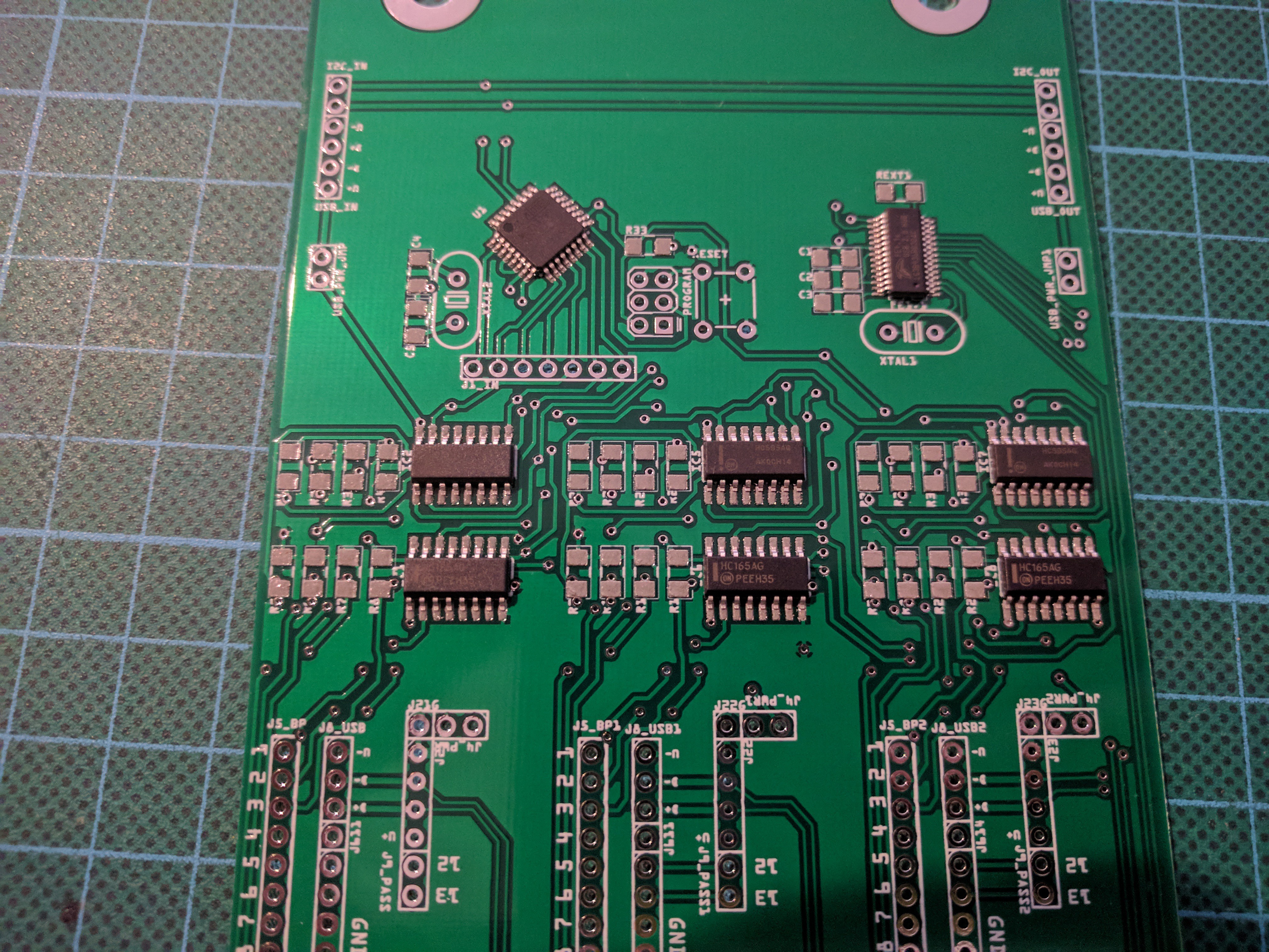
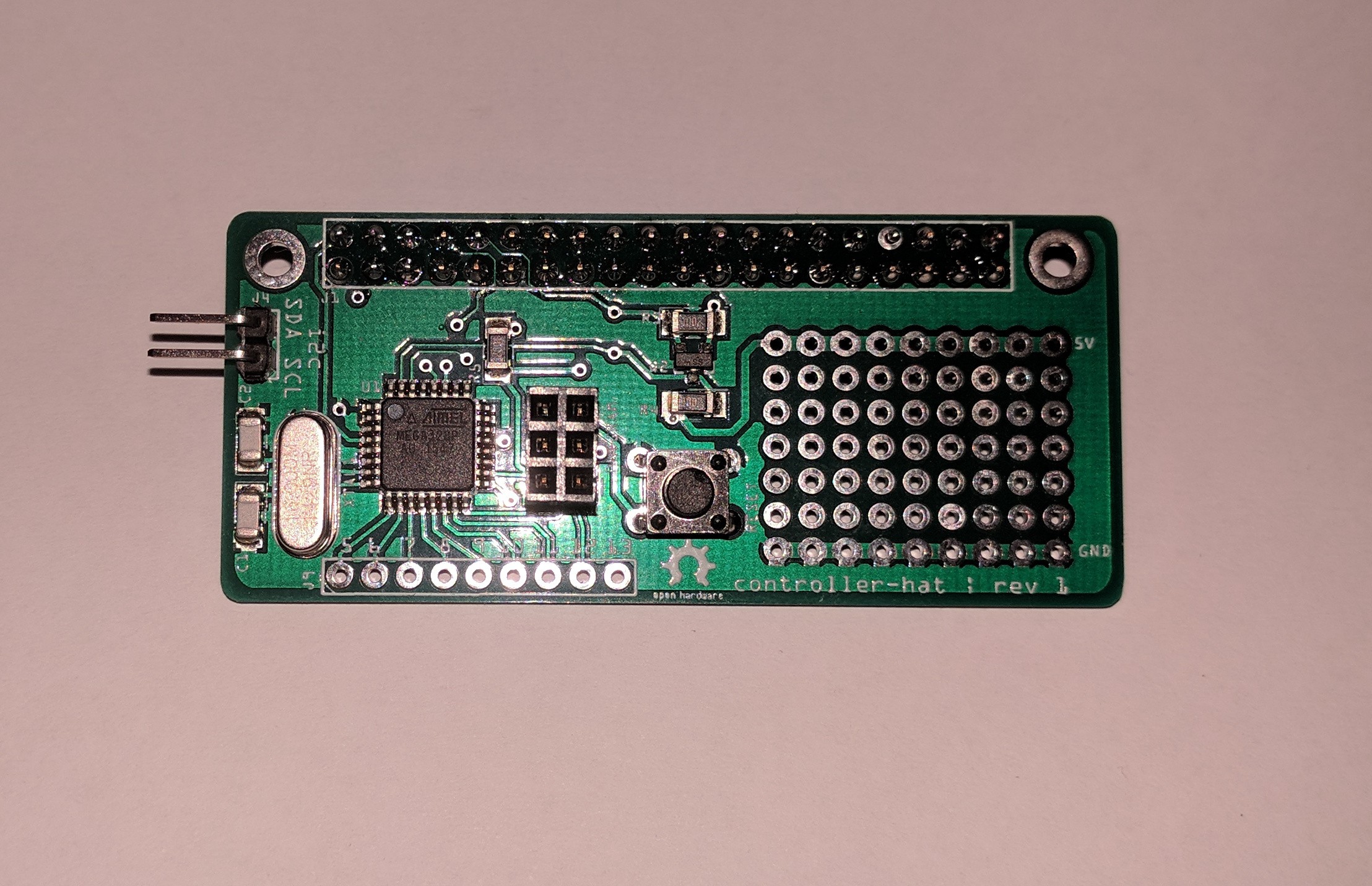
This is the board, it has pins 5-13 broken out for other use, plus a small prototyping section. In case you would want to expand the functionality of the control software.
![]()
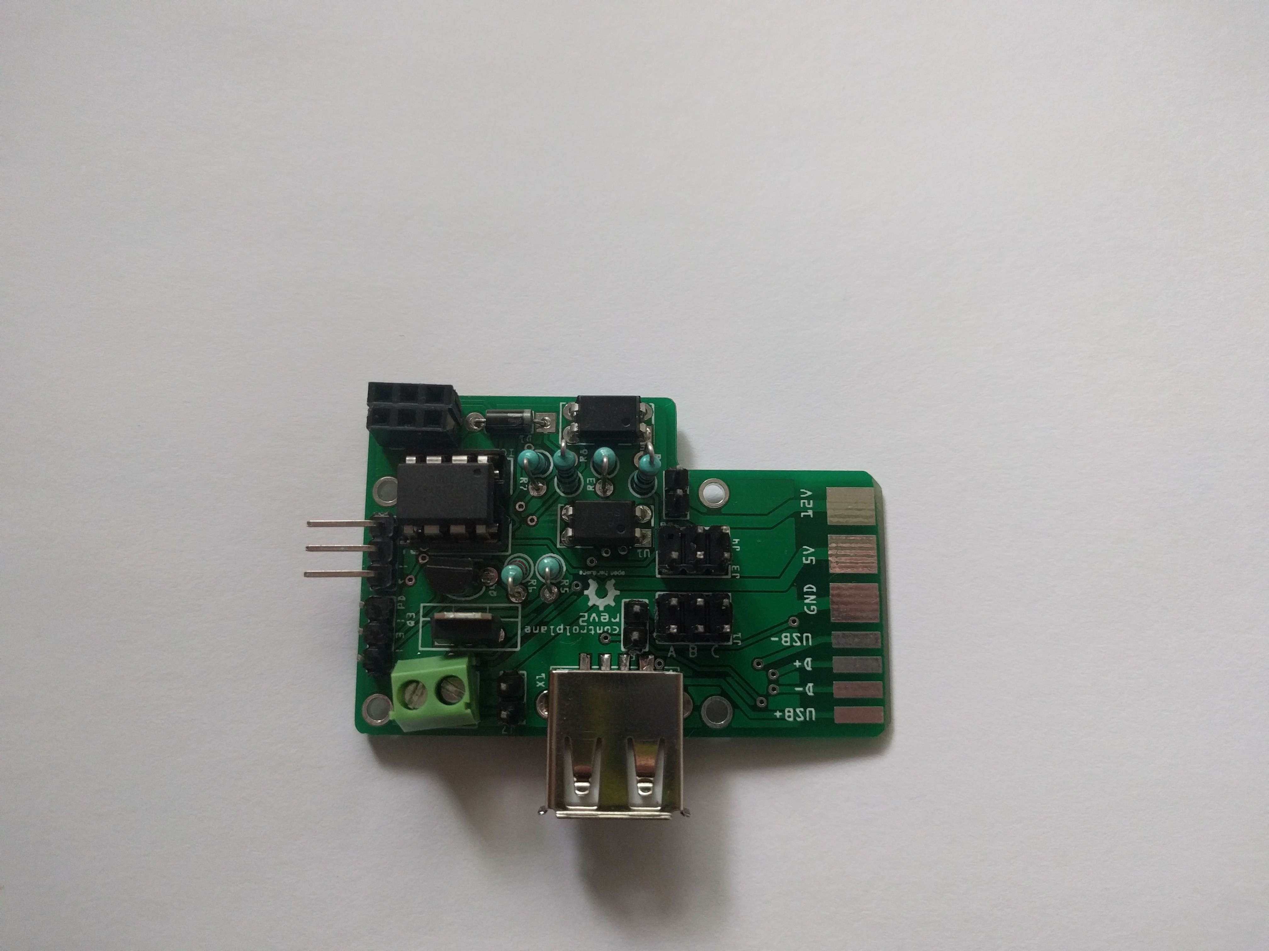
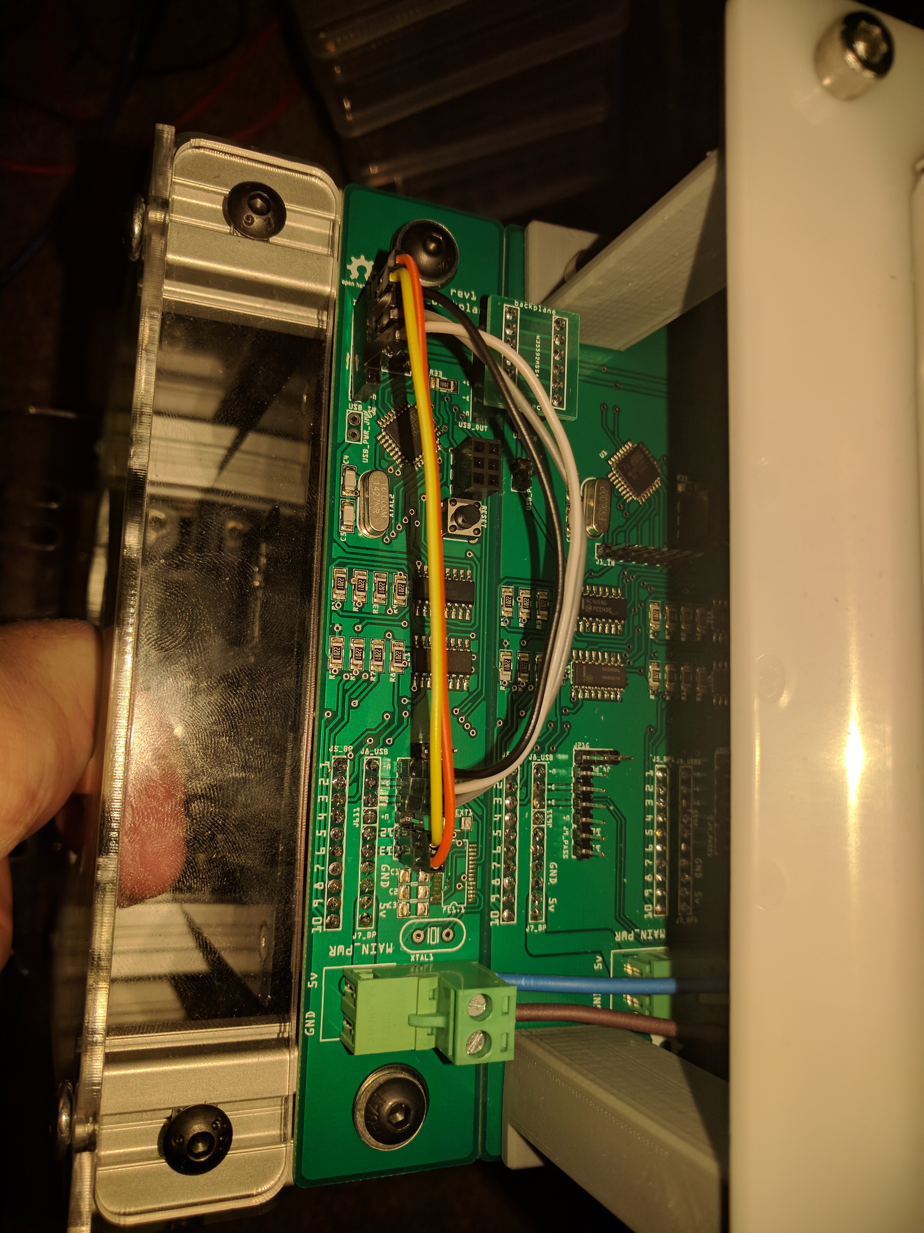
This is the first revision of the single slot backplane, it is picture with a USB hub onboard (unsoldered now), but this is being removed in revision 2 as it is not required. Revision 2 removed the requirement for the jumper leads and has i2c passthrough as a jumper only setting so it can be used either as a standalone final slot, or as the primary slot.
![]() I also have new backplane boards with integrated USB hub and atmega328s onboard 3 slot backplane units.
I also have new backplane boards with integrated USB hub and atmega328s onboard 3 slot backplane units.![]()
I have been hard at work writing software and learning a new programming language (go lang) in the process.
I've started uploading a lot of the code into github (https://github.com/spacklerindustries) already. I'm containerising most of it and turning things into services.
spackler is the control software for interfacing with the controller-hat board that talks to the backplanes.
loomis is the serial console server that detects when a caddy is inserted with a USB serial device and will start shellinabox
bushwood is the over-arching software that can talk/listen to the other services
bakery is piaas which I discovered while researching something completely unrelated to raspberry pis, and replaces a bunch of ansible playbooks i originally was going to use. bakery will eventually transform into a new service called webb
To get started you need a single raspberry pi running bushwood and spackler.
Documentation will eventually make its way to https://docs.caddyshack.xyz/
-
New prototype and changes
04/10/2018 at 23:10 • 0 commentsI recently got a bunch of new prototype boards back from the PCB fab. I've been assembling them and redesigning the enclosure to work with the new boards.
I've moved to having each backplane board containing 3 slots on them, they have a single i2c bus that links across the top of the board. One board then connects to the 2 breakout pins that pass the bus into one of the backplane slots to the dedicated MQTT master board for communication with greenskeeper.
I also broke out the USB passthrough to a micro-usb socket, which then has a cable that runs to a dedicated 13 port USB hub, which is then plugged into greenskeeper for managing the console servers for each caddy (if present)
After playing around with it a bit, I think I need to look at incorporating a USB hub onto each backplane board instead of having a dedicated USB hub with cables running from each backplane unit to it.
For now it is suitable for testing the core functionality out, and I will redesign the boards to have a FE1.1S on each one so they are linked, and pass through the first USB hub via a breakout cable that plugs into greenskeeper. This will reduce the number of cables required between the boards considerably.
Here are some pictures of the new enclosure, including the new PSU mounting plate and backplane boards.
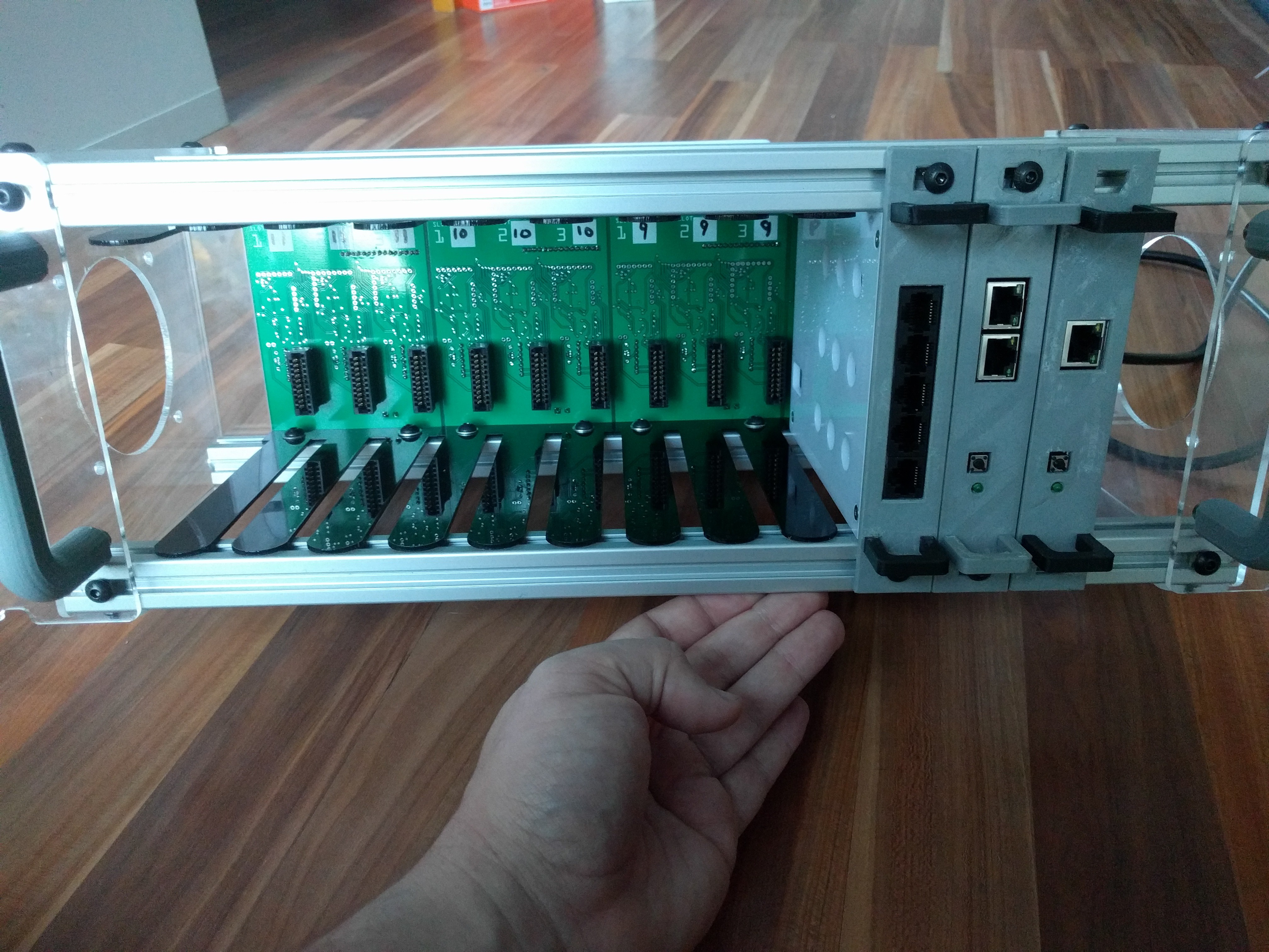
First up, front view. I've laser cut all the enclosure parts to reduce the amount of 2020 extrusions that are required. I also laser cut some slot dividers to aid in caddy insertion so that the backplane and control cards insert correctly.
![]()
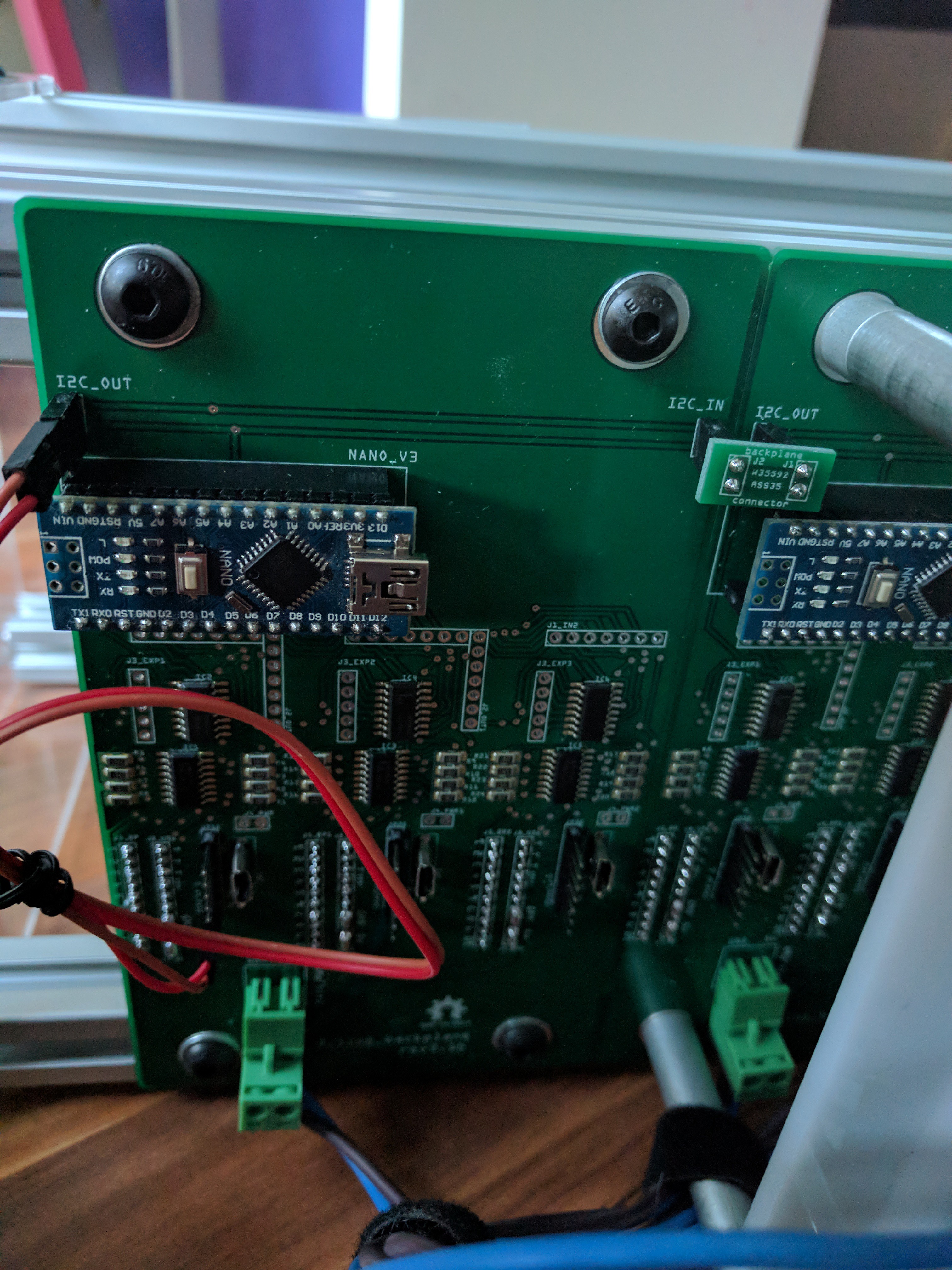
Next up, a pretty poor view of the backplane board. I left a lot of pin headers on this version for testing, but these will go away in the next version with incorporated USB hubs. I'll also be converting the nano to a dedicated ATMega328 instead of requiring the nano. This should free up some space to fit the USB components, and make things a bit more streamlined. I'll also re-orient the power connector so that its horizontal, to make it sit better.
![]()
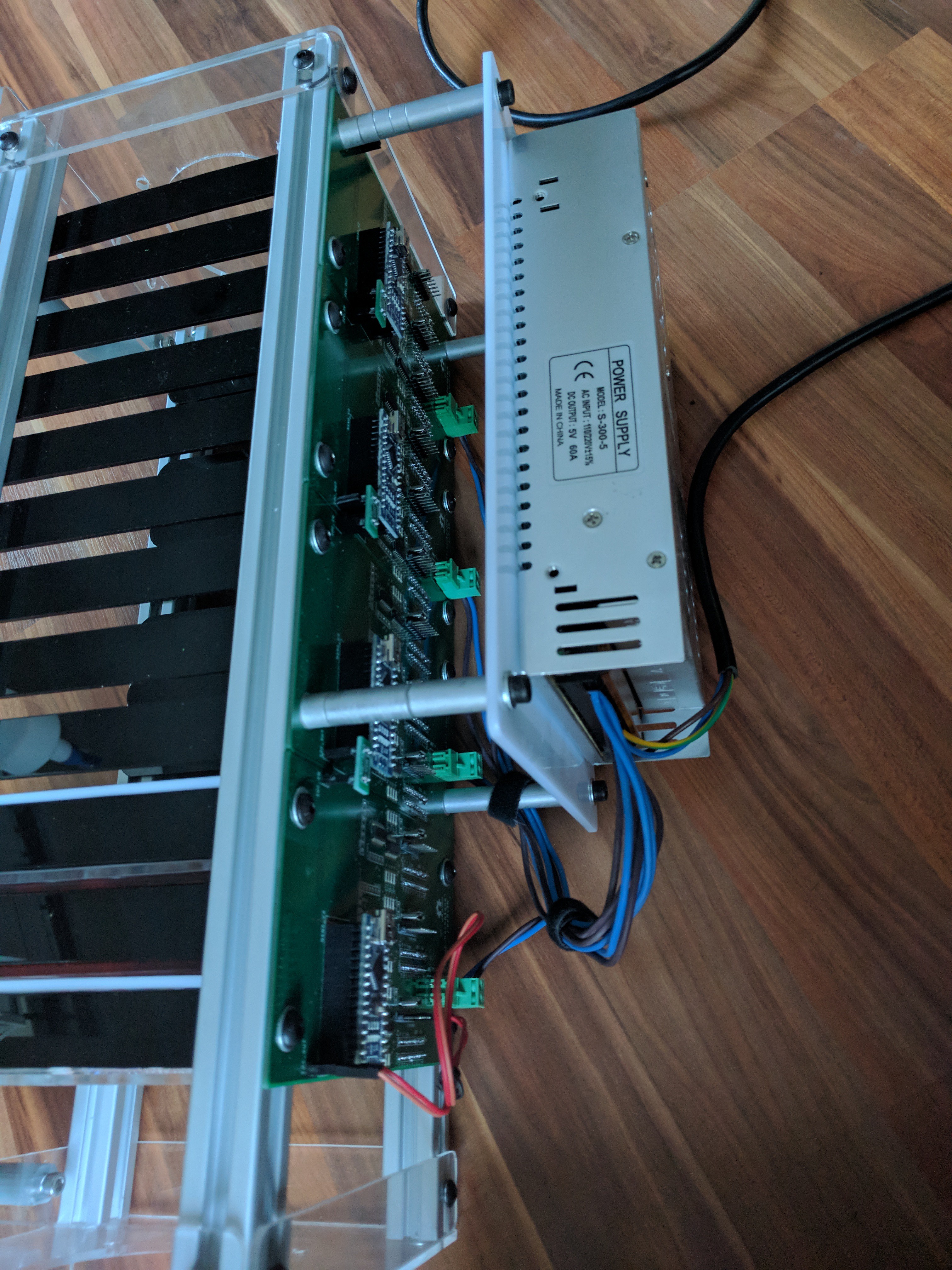
And the Power supply mounting plate. Instead of using 2 slots up for the power supply like I originally intended, I decided to move it to the back of the unit and beef it up a bit. This is a 5v 60A PSU, should be plenty. Average RPI requires 1-2.5A, the rest of the components are relatively low powered too so might be able to get away with 2-3 shacks running off a single PSU.
![]()
Part of the whole process is also trying to isolate the caddyshack from any other networking. To do this I am looking at adding a small router of some sort as a dedicated resource for the caddyshack. Currently I'm evaluating an Orange Pi R1, it has 2 ethernet ports (only 100m though :( ) and wireless. I'm looking at either OpenWRT or ZeroShell as the software running on it, it depends which one has the best support for wireless.
The caddyshacks would then have their own dedicated subnet with DHCP, using NAT to access the internet via the "WAN" port which would connect to your existing network and get an address via DHCP from your home router. Wireless can be used either for client connections directly into the caddyshack network, or for SBCs that want to utilise the wireless instead of cables. You could even configure your home router with a static route to the router in the caddyshack so you can access it from your home network, or use a host route on your desktop/laptop to access it.
I'm also evaluating other boards like the ODROID HC1 to use for a storage controller, hopefully post some information about this soon with how it would be used.
-
MQTT and moving to sort of microservices
02/19/2018 at 07:36 • 0 commentsI've decided to go ahead and redesign the backplane boards to use atmega328p on each board so that I can relocate the power control circuitry into the backplane. This allows me to utilise i2c on the backplane units and a single bus for control.
While the PCB manufacturer I've been using is away celebrating, I have taken the time to redesign the boards, and prototype with breadboard versions.
The re-work involes the removal of the initial greenskeeper controller board that I designed which made use of the MCP23017 IC, and replacing it with a single arduino with an ethernet adaptor connected to the i2c bus that the backplanes are all connected to.
Using i2c means it can be expanded to around 118 individual slots, obviously this is a lot of raspberry pis, and if you wanted to utilise USB->Serial for each slot, you would need 118 usb ports!
Re-writing the software side to be more microservices based, where:
- a MQTT broker runs in its own docker container
- a Redis runs in its own docker container
- a USB-Serial console management service run on a physical raspberry pi (it needs usb and udev access, difficult with docker and sorta pointless)
- The greenskeeper dashboard runs in its own docker container.
Redis is used for the communications with the dashboard using SSE.
MQTT is used for all other service communications.
When inserting a caddy, the console management service will detect if a USB->Serial device is in the caddy and update greenskeeper. The backplane will detect the type of caddy inserted based on jumpers that are set on the control interface, and will update greenskeeper with the status of the caddy.
I think this is better than the older method, and it also means that anything that is in docker can be run anywhere as long as they can communicate via MQTT.
Console management server has nginx using proxy_pass which (once implemented) would allow per user access to certain consoles.
In my demo caddyshack, I am currently running a 3 node 1 master kubernetes cluster, which is where I am running my tests of the new software and communication stack.
I'm hoping to get new boards made up and move everything into it in the next few weeks.
-
Greenskeeper Boards
12/23/2017 at 03:22 • 0 commentsI got my new Greenskeeper boards back from the PCB house and started soldering the parts on.
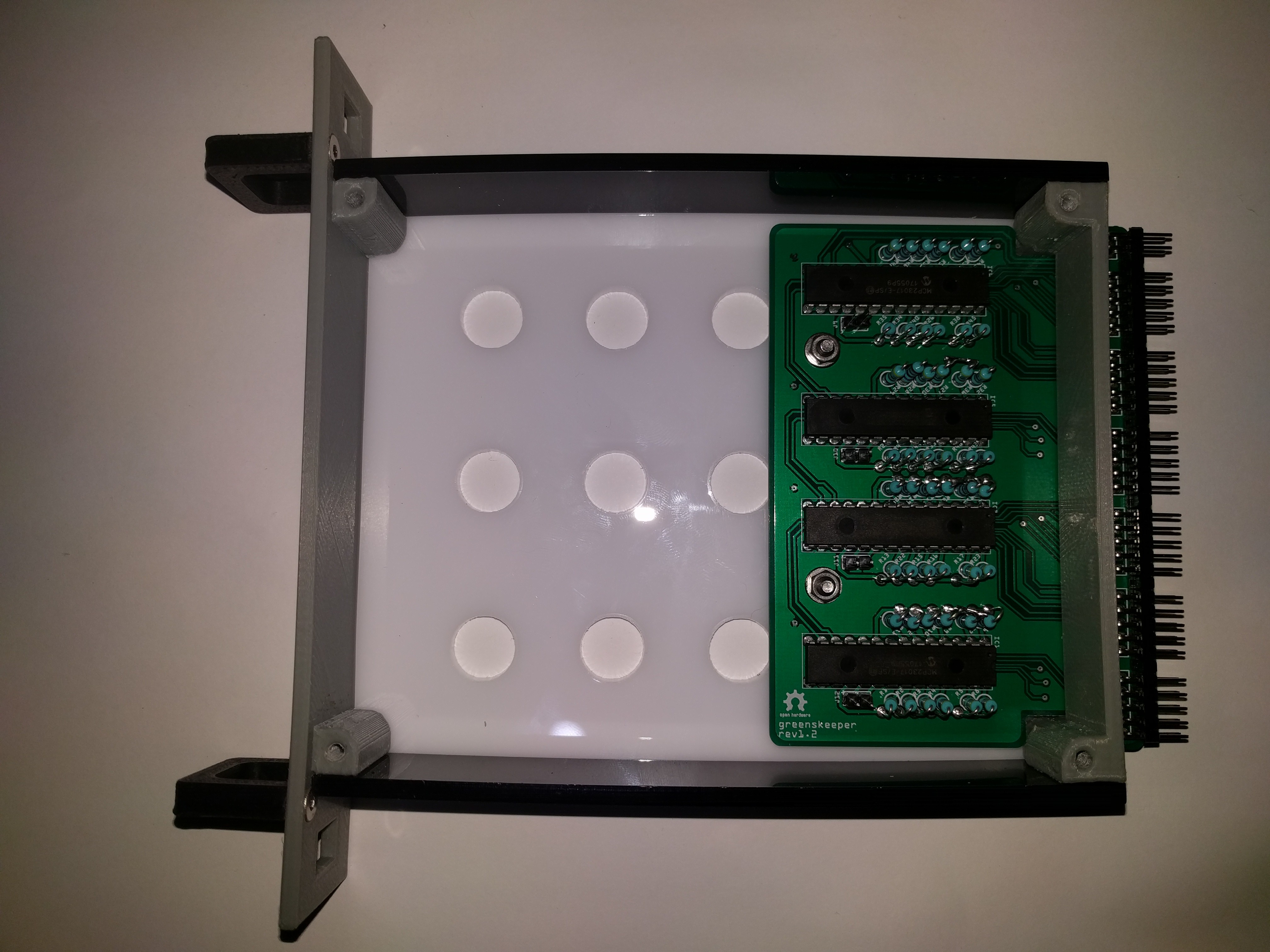
The main greenskeeper board came back great, and works as intended. Mounted inside its caddy, it provides I/O for 12 caddies. As each Shack has 13 slots, the 13th slot is reserved for the Greenskeeper caddy, which contains Greenskeeper and GreenskeeperUSB. USB is for serial console functionality and isn't required unless you want to run consoles.![]()
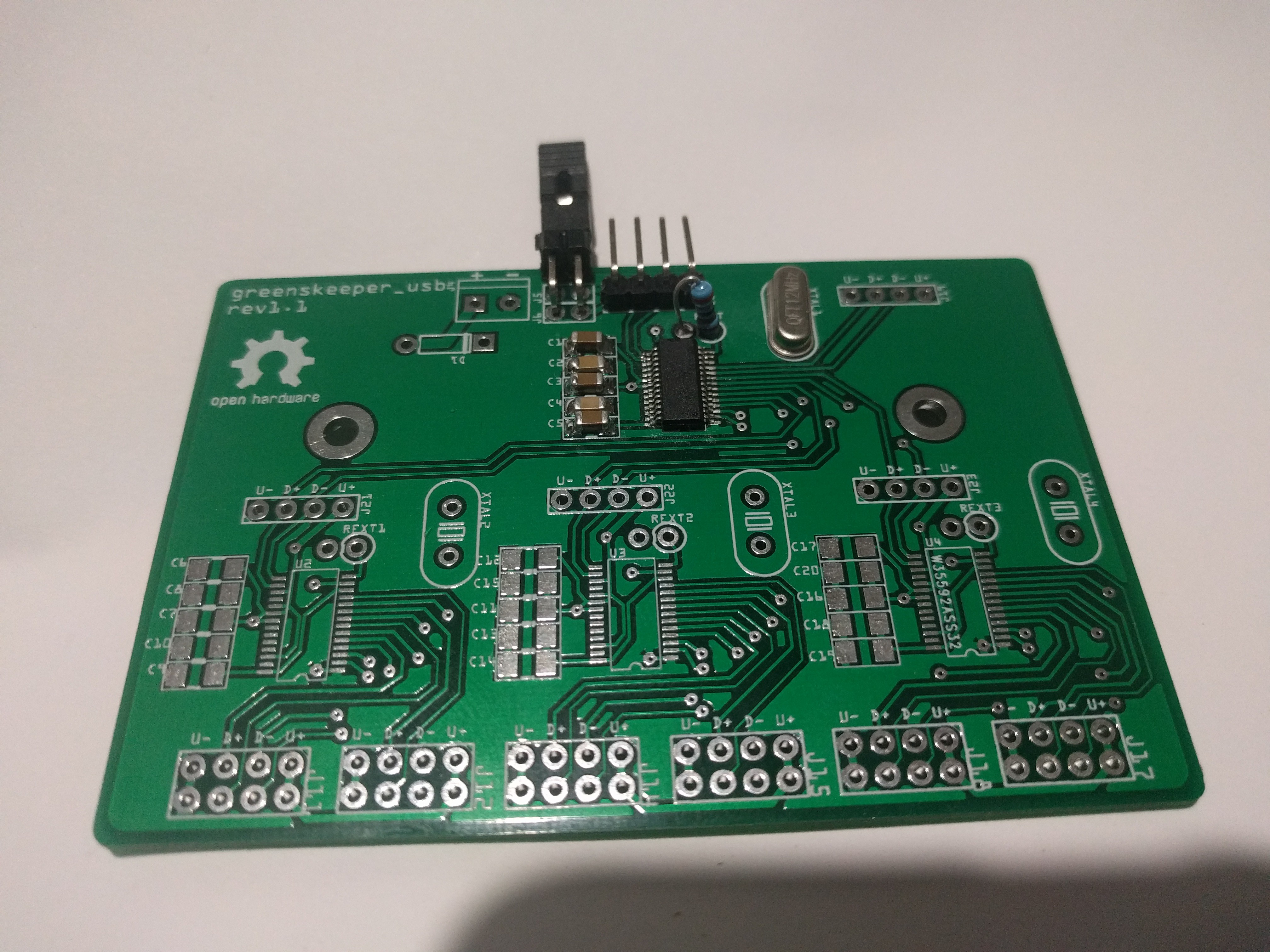
The other board that came back was GreenskeeperUSB, this is my first attempt at SMD soldering. I got the schematic for the USB hub from the numerous RPI Zero USB hubs that people have designed.
Either the FE1.1s I have are borked, or the schematic I followed is wrong, or I just soldered something wrong, but it doesn't detect properly.
For now I will be using a 13 port USB hub from eBay that has 4x FE1.1s chips on it, which almost exactly what I need but the form factor is wrong and it doesn't fit in a caddy properly.
This is the board.
I only soldered up the 1 chip to test that it is detected, but it isn't. I have ordered some additional FE1.1s, hopefully they arrive soon so I can check that it isn't just a bad batch of them. The first ones I ordered were just inside a small zip baggie, not even a anti-static bag.
![]()
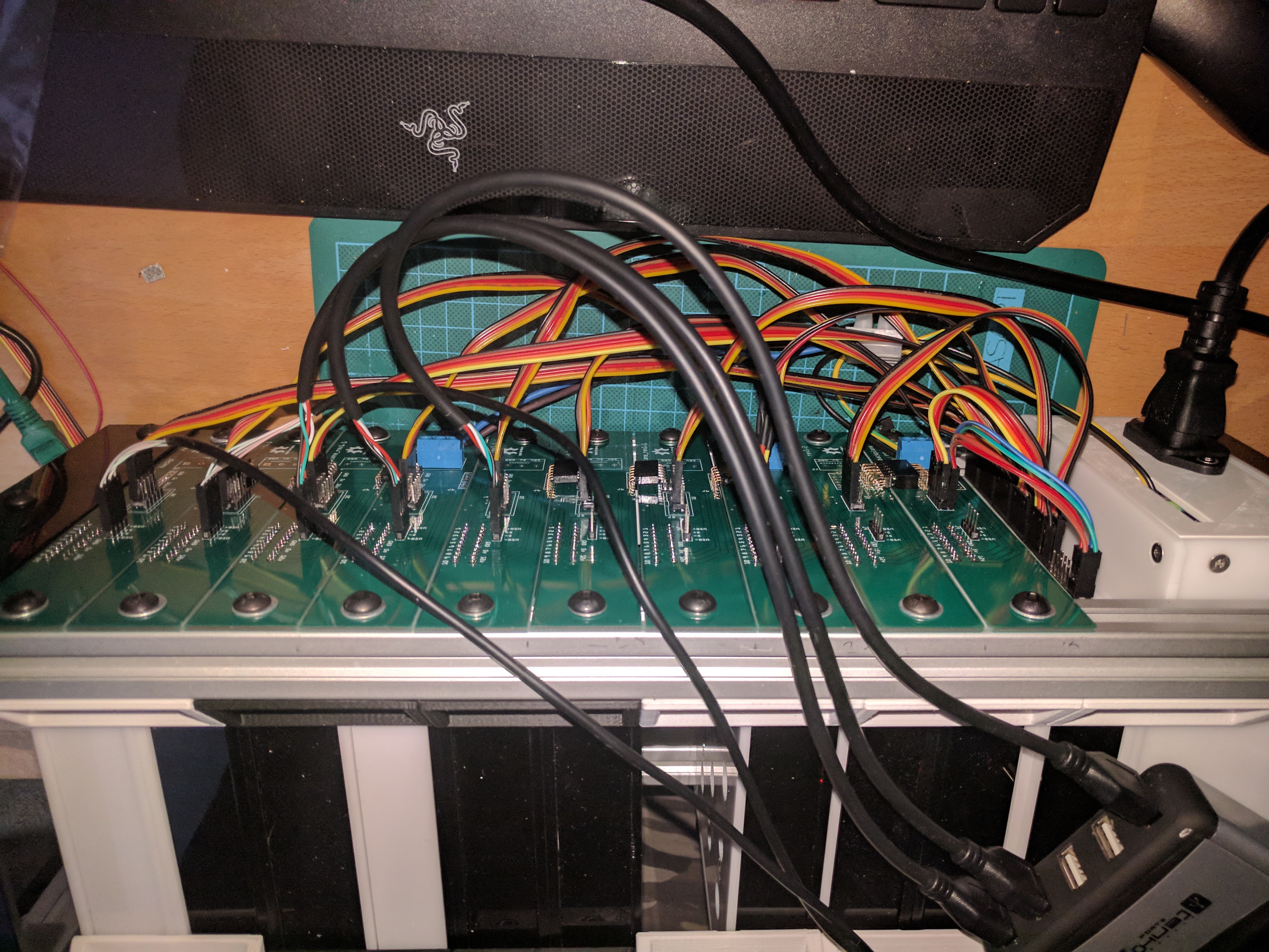
For now, the USB hub will do, but once I am free from the USB hub, and can use my own boards, then the unit will be much more compact.
Once that is sorted, I can look to make a cover for the rear to cover all the cables up.
![]()
I think the backplane mess of cables could be reduced if there was a low cost GPIO port expander that allowed for more than 8 addresses, the MCP23008 would be perfect for each individual backplane with a shared i2c bus all the way to the main controller, but they only allow for 8 addresses, where I would need at least 12 addresses per shack, using a multiplexer to expand the number of shacks you can run.
If anyone knows a low cost GPIO port expander that can have 12+ addresses, let me know. Another option I toyed with was an atmega168/328 on each backplane to act as a port expander, but this would increase the cost for each backplane considerably.
-
Prototyping
12/16/2017 at 02:10 • 0 commentsI'm currently prototyping the build, I've done a few revisions so far of the boards used in the build, I think I've settled on the backplane and control boards, but I'm waiting on the arrival of the Greenskeeper boards.
I'm hoping that they will work as intended, most of the components are through-hole, except the USB board, which uses SMD components at 0.5mm pitch that I'm not that great with soldering by hand.
I'm also working through the software side of things, and I have a pretty stable platform so far.
I was hoping to utilise i2c interrupts on the Greenskeeper board to trigger events, but I need to spend some more time looking into that, currently there is a function that runs every second to poll the Greenskeeper bus and checks for status changes.
There is the ability to start/stop/hardstop individual caddies, there are jumpers on each control board that are used to determine the type of device that is inserted, currently 8 device types are configurable.
Control boards also have USB pass through to the backplane, so you can insert a USB->SERTTL adaptor for connecting to the serial console on the Raspberry Pi inside the caddy, there are udev rules that need to be configured for this to work though, but with the use of the Greenskeeper USB board, these will be easier to set up.
![]()
The control board contains an attiny85 with some code that is used to power on/power off devices that are connected to the screw terminals, for switching 5v only. 12v is listed on the card slot that could be used to pass through 12v from the backplane, but this is unused currently, as everything I've planned around this is 5v based. There are 3 jumpers that are used to set the caddy type, using binary 1,2,4 to get combinations from 0-7 to indicate the type, this is read in by the Greenskeeper board.
The caddies are fully 3d printable, but I have laser cut parts in acrylic to reduce print times, and only printed the parts that are not just flat panels.
![]()
 I also have new backplane boards with integrated USB hub and atmega328s onboard 3 slot backplane units.