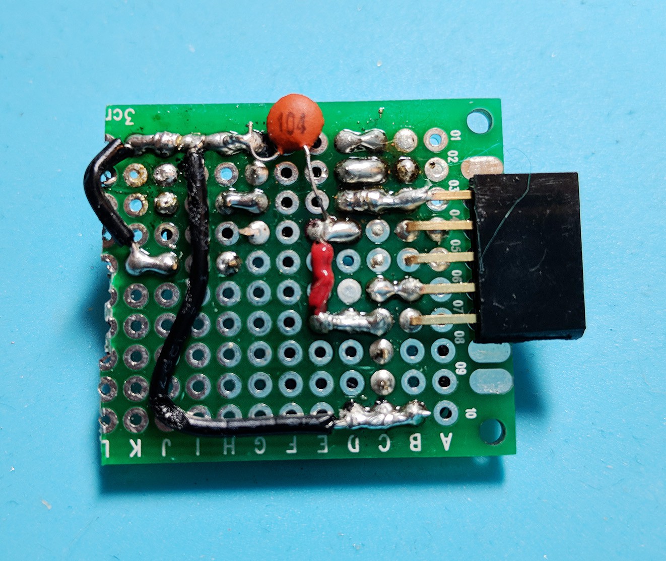
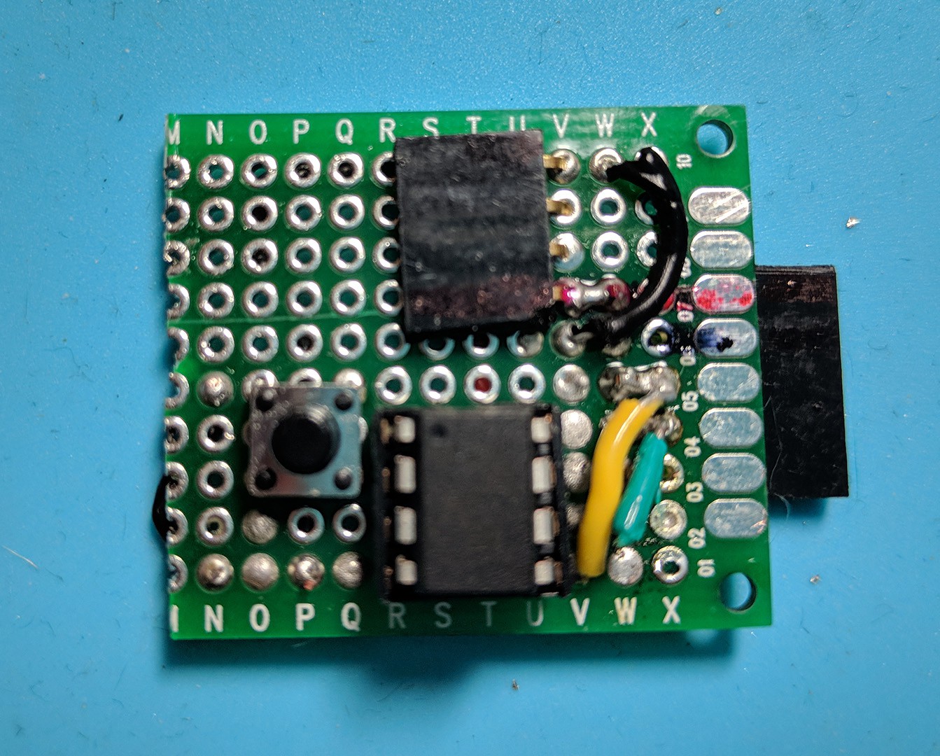
I cut a 70mm x 30mm PTH breadboard in half. Bent the long-leaded headers to 90degrees. The second header is for the DC-DC buck converter.
I didn't really have a plan on how to wire this I just kept referring to the breadboard and putting parts in different locations and orientations until it just "fit" best. I marked VCC with red and GND with black just to make sure I didn't release any magic smoke. As I mentioned before I again tried to connect the button incorrectly, thus the second (shorter) ground wire. When will I learn?
It was a PITA soldering this... it would be nice to DIY a custom PCB.


 Todd
Todd
Discussions
Become a Hackaday.io Member
Create an account to leave a comment. Already have an account? Log In.