-
Keeping better tune
10/03/2018 at 02:03 • 0 commentsSo the original Delta Flyer has a 20khz sampling rate driven by being an integer number of microseconds for the MBED API's timer interrupt. I'm a little worried how much jitter that has, and maybe the problems that kept 40khz from being stable relate to limits of the API. For example MBED can't record ultrasound with basic analog input because every time you ask for a sample it take 3 samples at I-think-it-was 5 microseconds each and sends you the mode. I don't really have plans to pursue CD audio but both a faster sampling rate and operation with less jitter are desirable. Fortunately ST provides. The very-definitely sold at a loss Nucleos include all the bells and whistles, among them a 32.768khz RTC crystal. It might not be suitable for a board-nonspecific design but for myself and anyone who wants to work form one of these it should be great.
-
Shrinking the BoM to something almost reasonable
10/03/2018 at 01:54 • 0 commentsPart of the justification for the giant juicy slider pots on the Delta Flyer (and Delta Flyer 2 when I can scrounge the time to assemble it and move the keyboard up for testing) is that when you' go looking for potentiometers with physical controls on Digikey or the like they're all about a buck anyway so you might as well get nice ones. Also the other parts like the DIP switch bank and the DIN jack aren't cheap either.
This isn't the case if you buy from overseas. I'm seeing 10 packs of knob or volume-wheel pots for 70 cents and 4-packs of rotary DIP switches for 5 bucks from the usual places. Combine this with newly-standardized 3.5mm MIDI (and the assumption that adapter cables will be built) and we're looking at vastly less board space used.
Suddenly a board run for kits is an actual semi-reasonable idea. They won't be as gloriously physical as the DFs, but a retroenmodulator board could fit within the footprint of the Nucleo connectors and probably have room to spare for a badly needed audio amp, so it works with something other than powered computer speakers. Think something on the order of $20, probably with a margin. Assuming I ever find the time.
-
Possible alternative algorithms
06/12/2018 at 19:50 • 0 commentsSince this synth is fully software it will be possible to re-program for other algorithms, someone just needs to make the firmware.
An easy one would be subtractive synthesis from a square wave. FIR filters would allow pulling harmonics out of a square wave to make other sounds. Pretty standard stuff.
A more modern technique would be "simulation" techniques involving "digital waveguide synthesis" where a digital delay line and some filtering shape an initial impulse into a note.
-
Better IO pin choice
06/04/2018 at 01:54 • 0 commentsWhen we made the first prototype I didn't find the PDF schematics for the Nucleo 64 boards. We found that several of our pins didn't work for the desired purposes and we needed to rearrange busses using non-continuous pins. Fortunately this is easy with mbed, just probably bad for performance. Well I have the PDF schematic now so here's some pointers:
Today I learned a schematic symbol for jumpers or at least solder bridges, that's what all the arc symbols are.
ADC pins:
PA_2 and PA_3 are used for the UART to the ST-Link(we already knew that, and the bridge is closed by default obviously, bridge SB_61 to connect the ADC Vref to AVDD on PA_3, closing SB_62 and 63 would connect these pins to the PA_2 and PA_3 pins on the header)
PA_4 and PA_5 are the DACS (we knew that too)
PB_1 connects to its pin by SB64 or alternatively to AVDD by SB65, to the pin is the default
That leaves PA_0, PA_1, PA_6, PA_7, PB_0, PC_0-PC_5
Digital Pins:
PA_13 is TMS (I guess JTAG Test Mode Select)
PA_14 is TCK (I guess JTAG test clock)
PB_3 is SWO (I guess JTAG Single Wire Output)
PB_11 is connected to ground by a 4.7uf cap and apparently has no header pin
PB_12 is connected to the header by SB37 instead of AVDD by SB34
PB_13 14 and 15 are different pins on the F373 chip and there's a set of solder bridges that could be used to rewire this board for that chip
PC_13 is connected by SB17 to a pullup to VDD and Button USER to ground, which appears to have an RC circuit in parallel, probably to debounce.
PC_14 and PC_15 are connected to the 32768hz crystal
PH_0 and PH_1 can be connected to an 8mhz crystal across unpopulated R35 and R37 to achieve independence from the ST link which is usually providing it's own clock over PH_0, I don't know if PH_1 can be used for anything in the current config.
PD_2 seems to be an available pin somehow
PF_5 does not exist in this chip instead there is a VDD hookup through SB43, SB47 would connect it to a pin for chips that have it
PF_7 does not exist in this chip instead there is a VDD hookup SB31, SB30 would connect it to a pin for chips that have it.
So I know which pins not to use.
-
Building a better sine function
05/03/2018 at 22:10 • 0 commentsFM synthesis requires a lot of calculation of sine values, so speed is of the essence. My worry was that a normal sine function from a math library might concentrate on accuracy over speed and would take an unknown amount of time. To counter this I made my own, mostly by cheating. The original fast integer sine function for the Delta Flyer was lookup table based. An array of 4097 16-bit sine values was calculated with Octave and written to a source file. Mirroring allowed us to store only a quarter wave with the most significant 2 bits of the angle being the quadrant determining which way to proceed into the table and what sign to give the output. To deal with the missing 2 bits of entry precision 2 entries were pulled from the table and the bitshift constant multiplication of the last 2 entries used to create a linear interpolation for values between them. This worked, worked well, and was in line with what I remember of how the Yamaha chips were supposed to work.
I never did actually check if a calculated sine was slower than my LUT method. I did, however know that the method we used wasn't fast enough to allow a 40khz sampling rate with an arbitrary number of notes simulated with at least an earlier version of the synthesis function. If the synthesis interrupt routine ran over it would be called again before completion, the DAC would never be updated with the new volume, and the input routines would be starved turning the synthesizer silent and freezing it. The simple solution with only some days to work with was just to ignore the upper half of the human hearing range and set the sampling rate to 20khz. This was good enough to allow full sit-on-the-keyboard polyphony and cover the dominant tones of all the notes in our 49-key set anyway.
So, as a thing to do to keep myself technical while concentrating on trying to land my new-grad job I decided to actually benchmark and confirm that assumption. To do that I needed a calculated sine to test against, unfortunately I wasn't able to get the ARM DSP sine implementation out of my libraries (I'm assuming MBed doesn't keep it to ensure a platform-neutral library), so I just had to make my own.
The gold standard of calculating the sine wave with basic arithmetic is what's called a Taylor series: an infinitely long polynomial in the form of an infinite summation that fits a pattern.
In the case of sine. There's a few problems with this, first of which is that it takes literally all of eternity to calculate. The second is the number format: we want to pass in integers or, thought of a different way, fixed-point values between -1 and 1 while the above polynomial takes in radians, from -pi to pi. A few scaling constants could fix that, I guess.
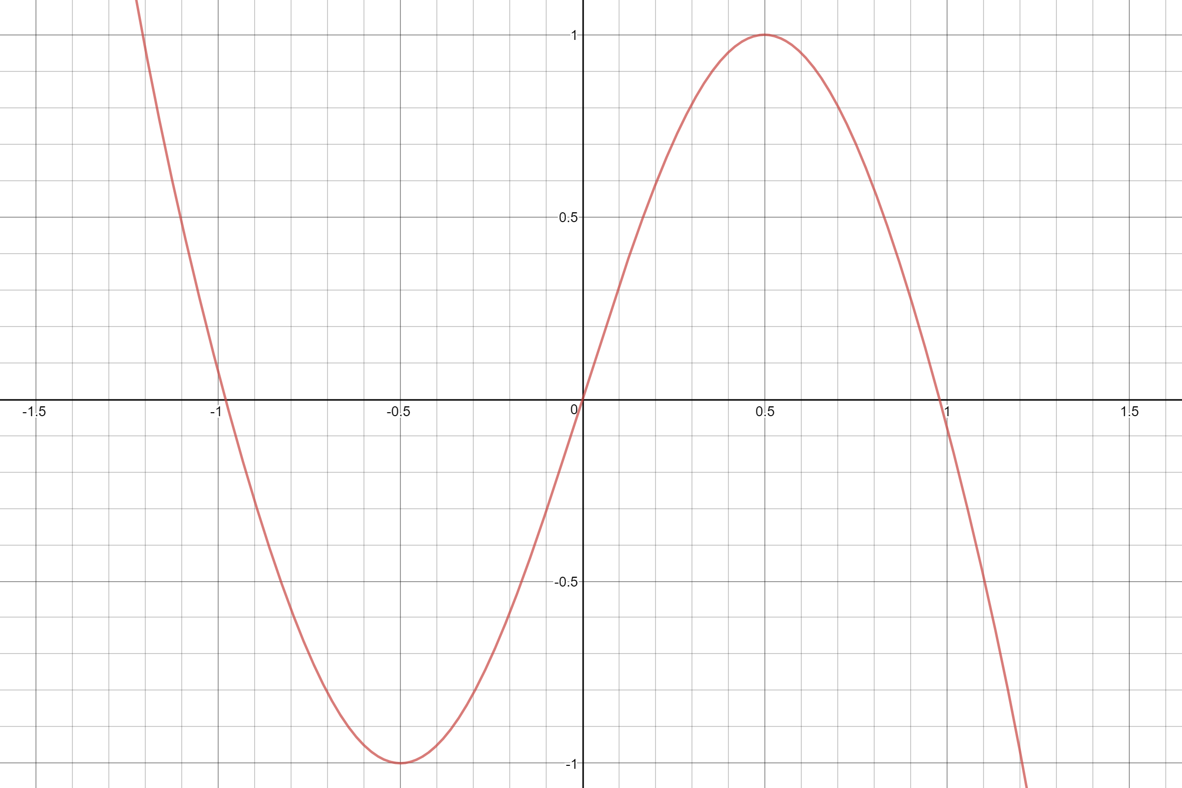
A nice helpful thing is that the above infinite polynomial is accurate for a sine wave of infinite length. With a little bitmasking all we really care about is the first cycle, as said above from -1 to 1. And our application is audio so the estimate doesn't need to be perfect in shape, just very good. If we stop the summation at n=4, the x^7 term of the polynomial we get a graph that's the right shape. The only problem is it crosses the X-axis at 0.98 instead of 1, about 2% early.
![]()
The source of this error is that the Taylor series is only maximally accurate with all it's terms. if you cut it off early it's not meant to give you an estimate of the same order. But we know an estimate of this order will work and give us about the right shape. So let's make our own, besides, multiplying everything by pi is getting old.
We know from the Taylor series, and from the basic fact that our desired graph flips when x goes negative that the polynomial we desire will consist only of odd-order terms. Now what are the desired features of our curve?
1st. It should reach value 1 at x=1/2.
2nd. That value is the maximum (if not we overflow our number format which is the integer math version of crossing the streams) so the slope or 1st derivative should be zero at x=1/2
3rd. It should be zero at x=1.
4th. (optional but we'll use it for best shape) It should be straight when it crosses the x axis. So the slope should not be changing, in other words the 2nd derivative / curvature is zero at x=1.
That's 4 facts to work with so we'll build a polynomial with 4 terms.
Let's use basic calculus and take the 1st and second derivative of that.
Kind of looks like a system of equations doesn't it? Let's put in our facts:
1.
2.
3.
4.
Well whatdoyaknow, we have 4 equations, and 4 unknown constants. This looks like a job for our frienemy linear algebra. Let's put all these in a matrix, scaling the fractional ones up just in case and putting the constant term in the right column:
And we'll feed it into an online row reducer because we aren't idiots who end up with errors because we did computation ourselves instead of using a computer.
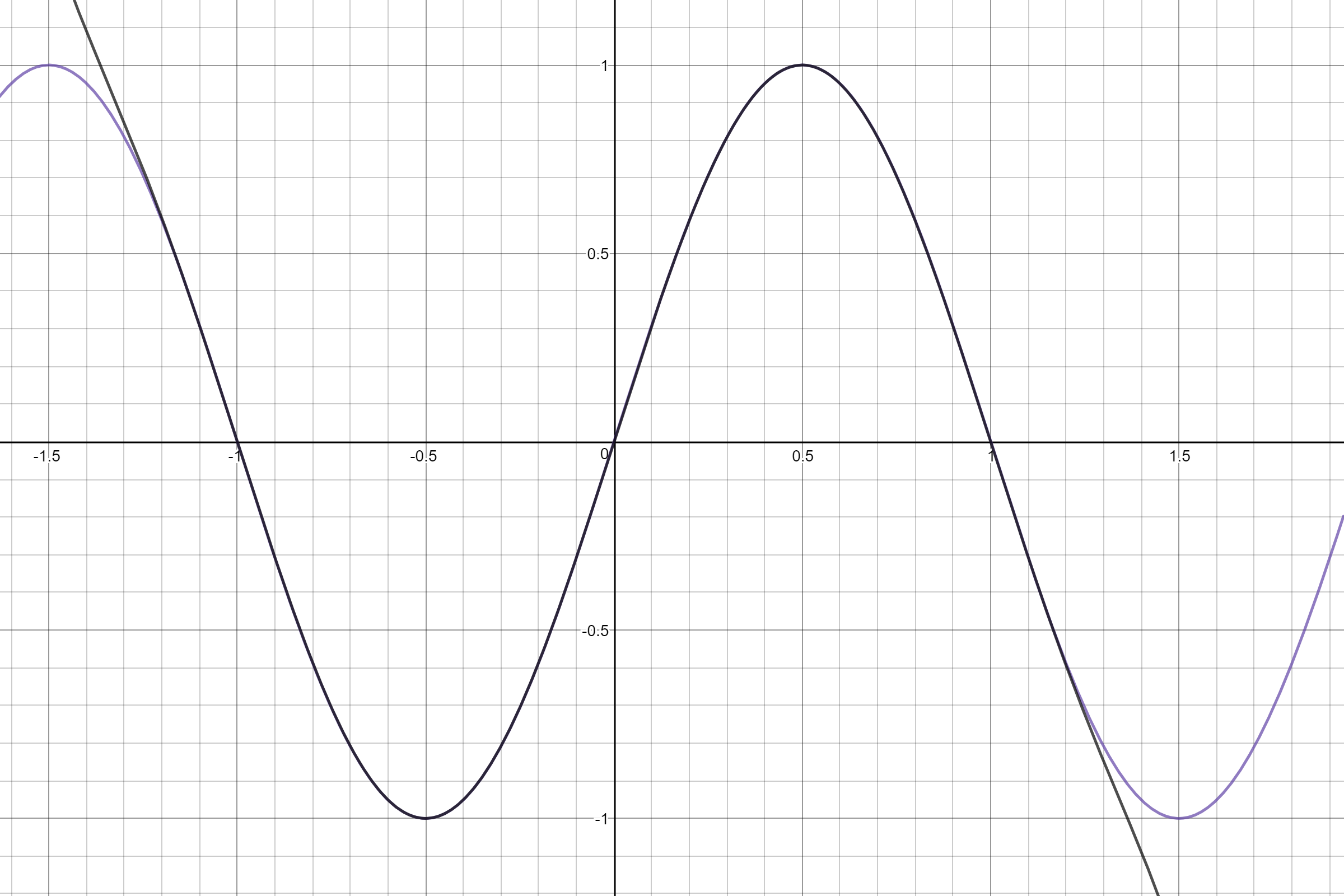
So our resulting polynomial is:
![]()
Yeah, that looks like it'll work just fine. Feel free to steal it, I'm sure it's been calculated before.
To turn this equation into an actual efficient algorithm in C we'll need some optimization as well as conversion into our number format. The low hanging fruit here is the exponents. You'll note that
So we can get our powers of x with only 4 multiplications (1 to get x squared, and one each for 3rd, 5th, and 7th powers). Also we know that division is slow, long-division is a guess and check series of subtractions that can't be added in a tree like multiplication so it's always one of the slowest operations available. So we won't use it. We're helped in this by our number format. Really we want to our answers to be between the upper and lower limits of 16-bit signed integers so all our terms are getting scaled by uint_16t_max of 32767. We can integrate that into our leading constants and get fractions large enough we can truncate them to integers with minimal error. We won't do that yet so here's the still-accurate equation:
Similarly we need to scale input to between -2^15 and 2^15 (an actual input of 32768 will get converted to -32768 by the operations we're using to handle input of greater angles anyway so we're safe) instead of -1 to 1. We'll call that input Q. So
which is a very nice expression of the bitshift we do after every multiplication to re-normalize. For example
has an extra 2^-15 which isn't part of our number format representing that we need to shift right 15 bits when we store our x-squared value for calculation. This is about to become important because it solves a problem we've been ignoring: those fraction constants we've been avoiding turning into integers? many of them are greater than 1 in our number format. This may seem like it's not a problem but if we feed in an angle near 1 the resulting value will overflow the 32 bits we've allowed for the result in our number format. Sure if we were working in assembly we could pull it from the high register after multiplication but C languages don't actually give us a syntactic way to do that. Instead we'll borrow a few 2^-1 until the constant is less than 1 and just renormalize by that many bits less after the multiplication. And here's our algorithm, I may need to tweak the rounding direction of our constants but for right now the results don't overflow the range and are accurate to within about 2/32767 which is well below the noise floor for our application.
int calcsin(const int phase){
    int x = (phase << 16) >> 16;//this truncates our input to 16 bits signed and sign-extends it
    int x2 = (x * x) >> 15;

    //beware!!! here there be magic constants
    int sum = (51385 * x) >> 14;

    int xblock = (x * x2) >> 15;
    sum -= (41914 * xblock) >> 13;

    xblock = (xblock * x2) >> 15;
    sum += (39072 * xblock) >> 14;

    xblock = (xblock * x2) >> 15;
    return sum - ((13261 * xblock) >> 15);
}
So now onto the actual benchmarking: I built a program that calculated samples for a sine wave (I think it was middle c at 20khz or something), as many as possible in a second. First using the LUT method with the table as a static constant (so in theory the compiler put it in flash), second with the table as just a non-constant global (to be put in code-segment RAM), and third with the above algorithm.
Here's the results:
5198338 sines calculated using constant custom interpolated LUT method in 1 second.
The last value was ffffabc9
5939341 sines calculated using non-constant custom interpolated LUT method in 1 second.
The last value was 6c3f
6195348 sines calculated using custom fixed-point polynomial in 1 second.
The last value was 5a76
Checking compass points of fixed-point polynomial.
Sine at zero is 0.
Sine at 1/2 is 32767.
Sine at -1/2 is -32765.
Sine at nearly 1 is 2.
Sine at -1 is 1.
Sine at 2 is 0.
Of note is that, on the target board calculating the sine is a little faster, but only just barely. With a slightly better coded function I might get it to optimize further, or use hand-tuned assembly to really make it work, but it's already faster. However, this is on an STM32F446 running at 190mhz with a real multiply and even MAC. There's a very good chance on any slower chip a LUT method would still be faster, even if it's the best option here.
The Delta Flyer
A "clean room" implementation FM synth using the mbed libraries.