OPL2LPT is an FM synthesizer board for parallel port.
The kit uses all 80’s style classic through hole components.
No SMD soldering skills required
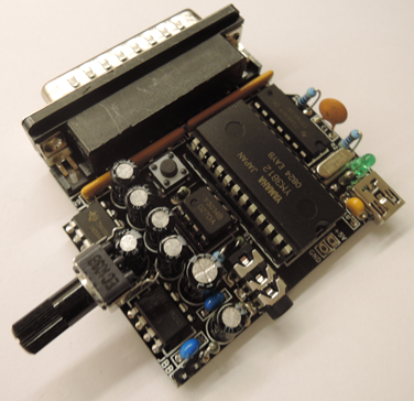
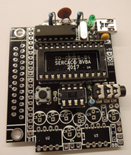
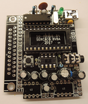
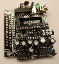
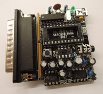
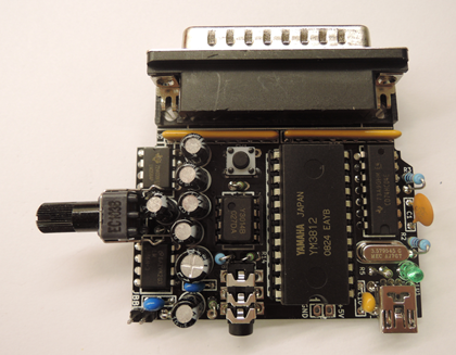
After approx. 40 minutes of soldering pleasure, you should end up with this beauty : The OPL2LPT !
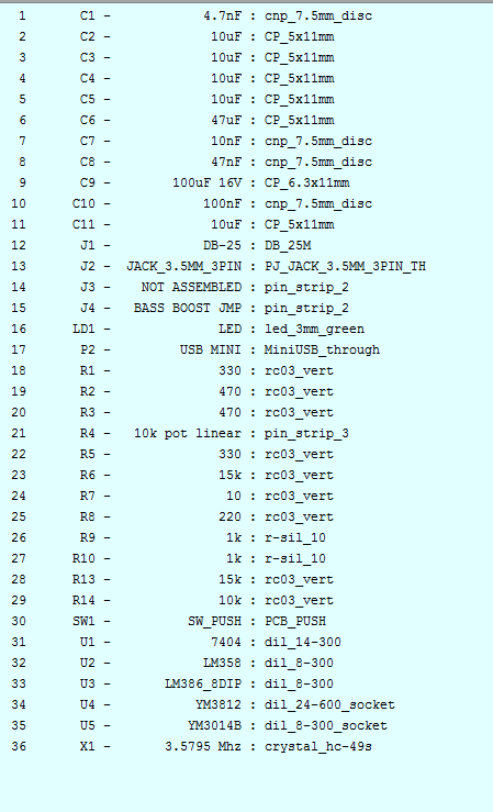
Parts List :
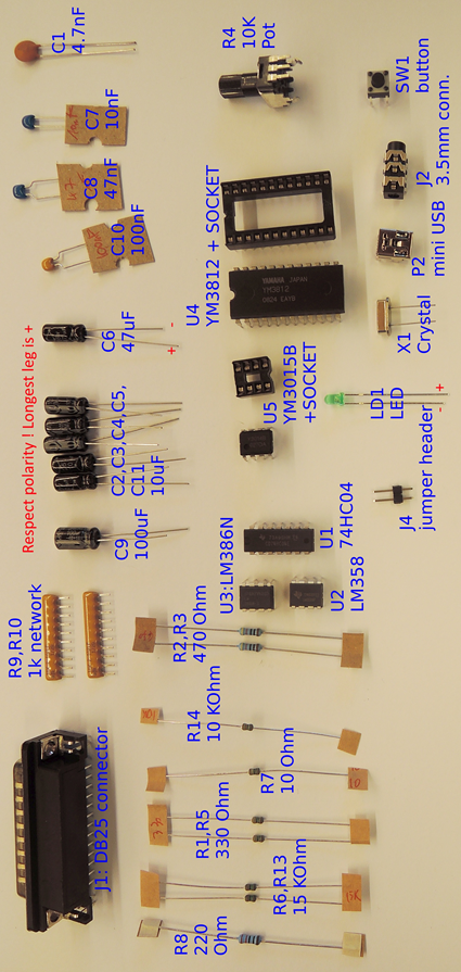
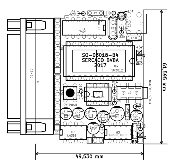
Component identification :
Component placement
For LD1, C2,C3,C4,C5, C6, C9, C11 : take care to respect the polarity. The negative side is marked with - on the PCB.
Soldering steps
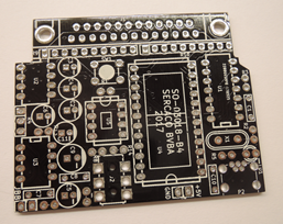
Starting from the blank PCB, gradually populate the board with components.
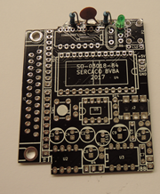
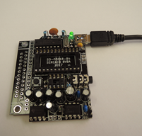
At this stage you can already test if the 5V power works fine : if there are no shorts , the green led should burn when you plug the board on an usb cable to your 5V power source. If this works, add the remaining components.
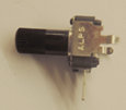
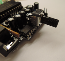
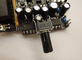
For the potentiometer, straighten the legs, and mount it as shown here :
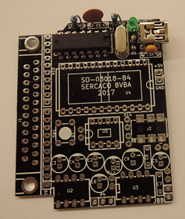
Now also place the Yamaha chips in the sockets. Make sure you insert them with the right orientation. If all went well, your board should look like this :
Testing the board
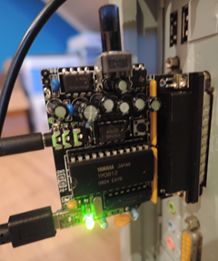
Plug your board in your DOS pc’s parallel port. Connect a 5V power source (this could be a battery pack, an usb port, a ps/2 to usb converter, …) to the board, using a mini USB cable.
Also connect your speakers or headphones to the 3.5mm jack.
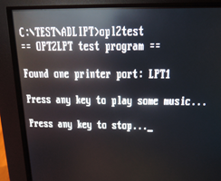
Now using the test program ‘opl2test’, you should hear some music.
Adjust the potentiometer until you hear a suitable volume.
 serdef
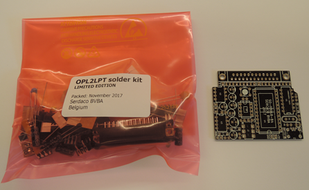
Discussions
Become a Hackaday.io Member
Create an account to leave a comment. Already have an account? Log In.