 Frank Milburn
-
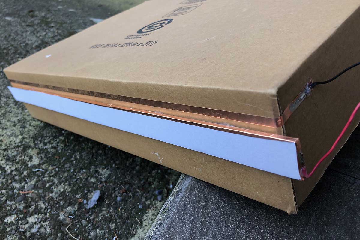
1Step One - Determine the best slope for the rails
Cut a piece of foam approximately 10 mm (3/8 inch) wide and apply copper tape to it. Attach it to a cardboard box or other scrap surface and experiment to see what slope and angles work with your materials that keep the coin rolling at a moderate speed. My experiments yielded 10 degrees.
![]()
-
2Step Two - Sketch out the tree
Sketch out a tree with LED placement to start with the following things in mind:
- The slope of the ramps is determined in the previous step - mine was around 10 degrees
- The foam used for the rails will extend the width of the tree
- Negative rails to light the LEDs around 5 to 10 cm (2 to 4 inches) in length seem to work well
- The drop between one rail to the next must be sufficient for the coin cell to pass
- Where possible, keep the LEDs near the end of the negative rail (makes soldering faster)
-
3Step Three - Cut out the tree and rails
The tree can be cut out with a sharp hobbyist knife if made from foam board.
From the left over foam board cut out the foam rails. Rails that are approximately 10 mm (3/8 inch) deep work well. Attach copper tape to the edge of each rail and wrap it around the edge.
Optional: At this point the rails could be attached to the tree with blue tack or other non permanent adhesive to make sure the slopes and angles are as desired.
-
4Step Four - Put it all together
Put the rails in place
- Glue the ramp (positive rail) first
- Cut a small slit at one end of the negative rail as close to the LED it will light as possible. Locate the slit about halfway up the diameter of a coin cell and slightly more than the width of the copper tape.
- Cut a section of the tape to the desired length.
- Push the end of the copper tape that will form the negative rail into the slit and then align it with the positive rail. The end pushed through the slit must be long enough to solder to.
Put the LEDs in place
- Use an awl or other sharp pointed object to make a hole that the LEDs will stay in with a friction fit
- Number the LED and it's associated negative rail poking through the foam board to aid in the soldering step that follows
Solder everything
- Solder the cathode of the LED to the corresponding negative rail. If thought out before hand, many of the leads from the LEDs can be overlaid directly onto the copper strip.
- Solder the anodes of the LEDs for each ramp together and then to the ramp itself with lengths of wire.
- Test each completed connection with a coin cell to make sure the LEDs light as you go along.
-
5Step Five - Test and tweak
You may find that your tree works on the first attempt. If so, congratulations! If not, here are a couple of things that can go wrong and a possible solution.
- The battery was put on backwards (Doh!)
- The battery is flying off the end (skipped step one did we?) - Try tilting the tree back more.
- The battery is still flying off the end - Cut the rail back a bit more, try a "deflector" similar to the ones on the bottom rails of this project
- The battery is not sticking to the rail below it - Tilt the tree back more, try a "deflector"
Testing the connections as you go along and using blue tack or some other method for track placement will prevent most problems.
Gravity Assisted Blinking Coin Cell Christmas Tree
The Blinking Coin Cell Christmas Tree runs entirely off the power of a coin cell with a bit of a gravity assist.
Discussions
Become a Hackaday.io Member
Create an account to leave a comment. Already have an account? Log In.