 Ted Yapo
I wanted to get started with FPGAs for a long time. Today, it finally happened. I bought a #TinyFPGA A-Series (A1 specifically) on Tindie, and started coding. After a few hours, I came up with a bouncing ball on a VGA monitor (starting from scratch).
I know there are simple VGA examples out there, but I resisted looking at them for the exercise. It's not super-complex, but a lot of things have to be right to get this to work. There are a few issues, mainly about the clock. I used the internal clock source on the FPGA, which isn't very accurate or stable. Additionally, the closest I could get to the proper 25.175 MHz dot clock was 24.18 MHz. The result is a little jitter on the display. I could solve this with an external oscillator, but this was just an exercise.
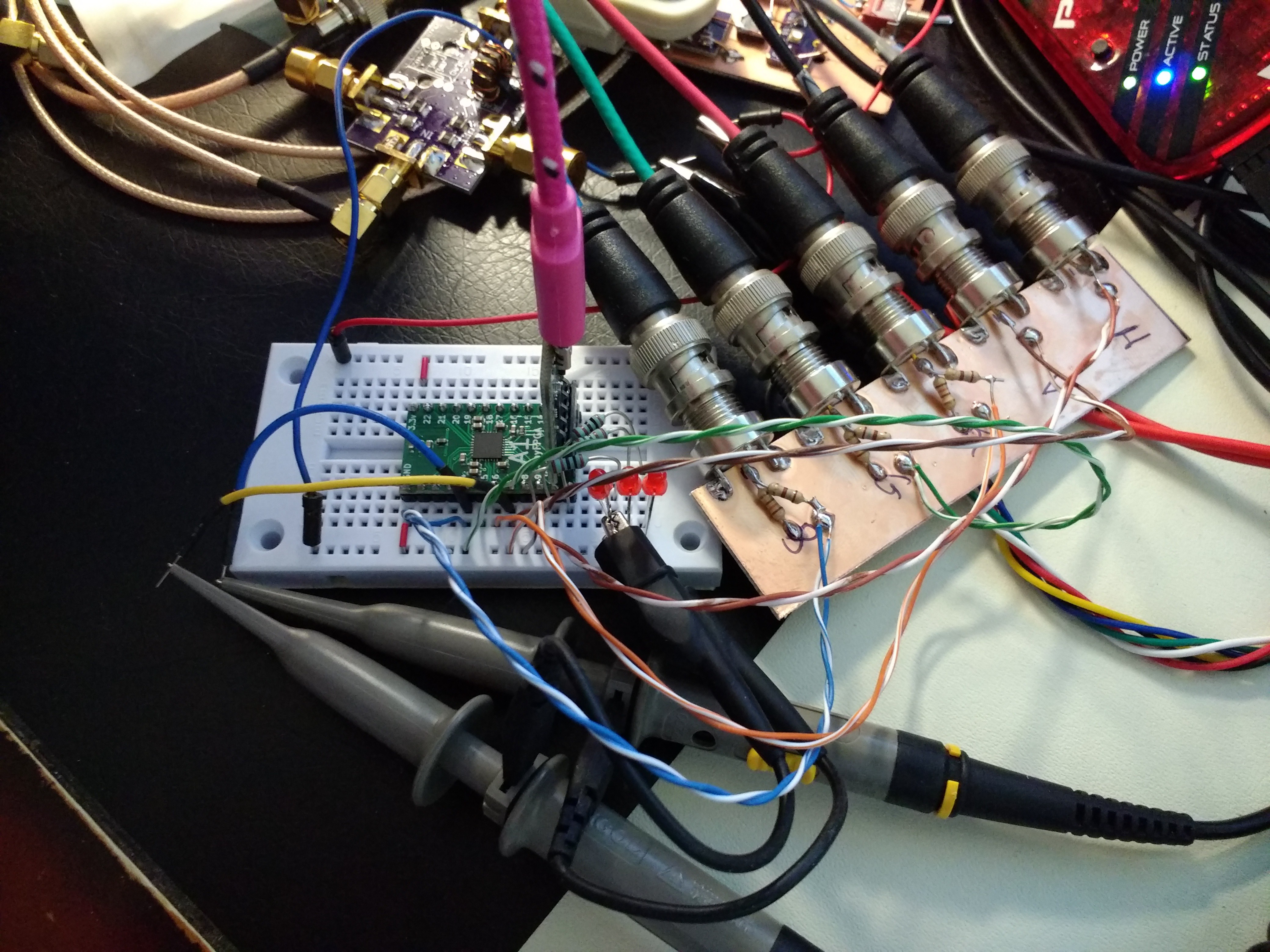
The hardware is simply the A1 board and six resistors to shift the RGB levels and provide a proper 75-ohm output impedance. I didn't have any VGA connectors around, so I used BNC's and an old-school VGA-to-BNC cable. There are a few in-progress projects in the picture, but you can locate the TinyFPGA and the BNCs. The three LEDs from the example in the TinyFPGA documentation are still in the breadboard :-)
The verilog code could probably be prettied up a lot, but at this point, I'm just excited to have something going. This is sure to give experienced RTL jockeys a good laugh:
module TinyFPGA_A1 (
  output pin4_mosi,
  output pin5,
  output pin6,
  output pin7_done,
  output pin8_pgmn
                    );

  wire clk;
   OSCH #(.NOM_FREQ("24.18") // should be 25.175 - close enough!
          ) internal_oscillator_inst (
                                      .STDBY(1'b0),
                                      .OSC(clk)
                                      );

   parameter ball_size = 20;
   reg [9:0] horiz_ctr;
   reg       hsync;
   reg [9:0] vert_ctr;
   reg       vsync;
   reg       hblank;
   reg       vblank;
   reg [9:0] row;
   reg [9:0] col;
   reg       dr;
   reg       dc;
   reg [2:0] rgb;
   always @(posedge clk) begin
      horiz_ctr <= horiz_ctr + 1;
      if (((vert_ctr-45) >= row) &&
          ((vert_ctr-45) <= (row+ball_size)) &&
          ((horiz_ctr-160) >= col) &&
          ((horiz_ctr-160) <= (col+ball_size)))
        rgb = 3'b100;
      else
        rgb = 3'b001;

      case (horiz_ctr)
        10'd16:  hsync <= 1;
        10'd112: hsync <= 0;
        10'd160: hblank <= 0;
        10'd800:
          begin
             horiz_ctr <= 0;
             hblank <= 1;
             vert_ctr <= vert_ctr + 1;
             case (vert_ctr)
               10'd10:  vsync <= 1;
               10'd12:  vsync <= 0;
               10'd45:  vblank <= 0;
               10'd525:
                 begin
                    vert_ctr <= 0;
                    vblank <= 1;
                    if (dr)
                      row <= row + 1;
                    else
                      row <= row - 1;
                    if (dc)
                      col <= col + 1;
                    else
                      col <= col - 1;
                    if (row < 1) begin
                       row <= 1;
                       dr <= ~dr;
                    end
                    if (col < 1) begin
                       col <= 1;
                       dc <= ~dc;
                    end
                    if (row > (479-ball_size)) begin
                       row <= 479-ball_size;
                       dr <= ~dr;
                    end
                    if (col > (639-ball_size)) begin
                       col <= 639-ball_size;
                       dc <= ~dc;
                    end
                 end
             endcase
          end
      endcase
   end

   wire frame_active = !vblank & !hblank;

   assign pin8_pgmn = !hsync;
   assign pin7_done = !vsync;
   assign pin4_mosi = frame_active & rgb[0];
   assign pin5 = frame_active & rgb[1];
   assign pin6 = frame_active & rgb[2];
endmodule
If I'm reading the output of the Lattice Diamond software correctly (doubtful), I've used 117 of the 256 available LUT's - less than half. I didn't think about optimizing the code at all - at this point, I wouldn't know exactly where to start.
I am really impressed with how easy this all is. Kudos to @Luke Valenty on a very nice project/product.
Discussions
Become a Hackaday.io Member
Create an account to leave a comment. Already have an account? Log In.
This is great! @Xark had previously attempted using the internal oscillator on the A2 for VGA but it seemed like his monitor didn't like it. I'm happy to see that it will at least work with some VGA monitors. Also fun to see what people can do with the teeny-tiny FPGA in the A1. Thanks for sharing your project :)
Are you sure? yes | no
Thanks! It also worked at 26.60 MHz with this monitor, but appeared to tear a little more on the left edge.
Are you sure? yes | no