Ted Yapo
-
How not to screw up mating PCBs
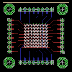
04/01/2018 at 17:46 • 0 commentsI've done a few projects where I need mating PCBs for some reason - holes or header connectors or both have to fit together. And, I've screwed a few of them up. For example, the top PCB in one sandwich I'm working on looks like this:
![]()
To get the mounting holes and headers in the right place, I decided to make a "template" PCB footprint that I could include on each board to make sure the mating components line up.
![]()
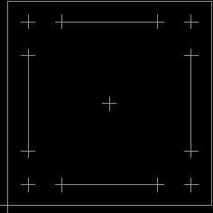
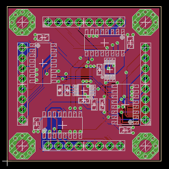
This "component" has registration marks in the "reference" layer for the centers of the mating components, and the board origin, outline, and center. With this, it's easy to make the other PCB(s) fit exactly:
![]()
No more messed up PCBs (for this reason, anyway).
-
Oscilloscope Sing-Along: Rotating Cube
02/04/2018 at 20:21 • 1 commentI read about Neil Fraser's audio-based oscilloscope art on the blog, and I got hooked. This time it's a rotating cube done in python. I've made a video of the result, and synchronized the wav file as the soundtrack, so you can hook an oscilloscope to your headphone jack and "sing-along" at home.
The cube is a bit jumpy because the low-frequency response of my soundcard doesn't extend down to DC, and the youtube audio compression takes its toll as well (odd wiggles), but it still works.
The output is best viewed on an analog scope, but you may have luck with some digital models, too. For instance, I found that on a Rigol DS1054Z, setting the Mem Depth (Acquire menu) to 6k, and turning the horizontal to 1ms works well.
Here's the python code, for those interested. The ScopeDisplay class is probably the most interesting part. The rest of the code just draws the cube, using backface culling to avoid drawing the hidden lines, but that's easily removed if you want to see them. I really enjoyed remembering all this stuff. Kids today are spoiled with their fancy depth-buffers!
If x- and y- seem reversed, just swap them on the scope. You've got a 50-50 shot of getting it right the first time :-)
#!/usr/bin/env python # this code is in the public domain import wave import struct import math class ScopeDisplay(): def __init__(self, sample_rate, filename): self.sample_rate = sample_rate self.wav = wave.open(filename, 'w') self.wav.setnchannels(2) self.wav.setsampwidth(1) self.wav.setframerate(sample_rate) self.wav.setnframes(1) self.data = [] def point(self, x, y): left = int(min(max(128+127*x, 0), 255)) right = int(min(max(128+127*y, 0), 255)) self.data.append(struct.pack('B', left)) self.data.append(struct.pack('B', right)) def line(self, x0, y0, x1, y1, step = 1): d = math.sqrt((x0-x1)*(x0-x1) + (y0-y1)*(y0-y1)) n_pts = max(2, int(step * d)) for i in range(0, n_pts): x = x0 + (x1 - x0) * i / (n_pts-1) y = y0 + (y1 - y0) * i / (n_pts-1) self.point(x, y) def close(self): self.wav.writeframes(''.join(self.data)) self.wav.close() display = ScopeDisplay(48000, 'oscilloscope_cube.wav') # cube points x = [-1, -1, -1, -1, +1, +1, +1, +1] y = [-1, -1, +1, +1, -1, -1, +1, +1] z = [-1, +1, +1, -1, -1, +1, +1, -1] # cube faces (indexes into points) faces = [[1,2,6,5],[0,4,7,3],[4,7,6,5],[0,1,2,3],[2,6,7,3],[0,1,5,4]] # face normals (for hidden line-removal) nx = [0, 0, 1,-1, 0, 0] ny = [0, 0, 0, 0, 1,-1] nz = [1,-1, 0, 0, 0, 0] # viewpoint pe{x,y,z} pex = 0 pey = 0 pez = 3 # cube size scale = 1/math.sqrt(2) # rotation speeds x_speed = 0.002 y_speed = 0.0001 z_speed = 0.00003 for i in range(0, 100000): # draw cube for f_idx in range(0, len(faces)): face = faces[f_idx] nx0 = nx[f_idx] ny0 = ny[f_idx] nz0 = nz[f_idx] for pair in [[face[0], face[1]], [face[1], face[2]], [face[2], face[3]], [face[3], face[0]]]: x0 = scale*x[pair[0]] y0 = scale*y[pair[0]] z0 = scale*z[pair[0]] x1 = scale*x[pair[1]] y1 = scale*y[pair[1]] z1 = scale*z[pair[1]] # rotate cube around y-axis theta = 2*math.pi * i * y_speed cs = math.cos(theta) sn = math.sin(theta) xq0 = x0 * cs - z0 * sn yq0 = y0 zq0 = x0 * sn + z0 * cs xq1 = x1 * cs - z1 * sn yq1 = y1 zq1 = x1 * sn + z1 * cs nx1 = nx0 * cs - nz0 * sn ny1 = ny0 nz1 = nx0 * sn + nz0 * cs # rotate cube around x-axis theta = 2*math.pi * i * x_speed cs = math.cos(theta) sn = math.sin(theta) xw0 = xq0 yw0 = yq0 * cs - zq0 * sn zw0 = yq0 * sn + zq0 * cs xw1 = xq1 yw1 = yq1 * cs - zq1 * sn zw1 = yq1 * sn + zq1 * cs nx2 = nx1 ny2 = ny1 * cs - nz1 * sn nz2 = ny1 * sn + nz1 * cs # rotate cube around z-axis theta = 2*math.pi * i * z_speed cs = math.cos(theta) sn = math.sin(theta) xr0 = xw0 * cs - yw0 * sn yr0 = xw0 * sn + yw0 * cs zr0 = zw0 xr1 = xw1 * cs - yw1 * sn yr1 = xw1 * sn + yw1 * cs zr1 = zw1 nx3 = nx2 * cs - ny2 * sn ny3 = nx2 * sn + ny2 * cs nz3 = nz2 # project points into screen space d0 = (1 - pez) / (zr0 - pez) xs0 = pex + d0*(xr0 - pex) ys0 = pey + d0*(yr0 - pey) d1 = (1 - pez) / (zr1 - pez) xs1 = pex + d1*(xr1 - pex) ys1 = pey + d1*(yr1 - pey) # cull back-faces based # on dot(normal, view vector) dot0 = nx3*(xr0 - pex) + ny3*(yr0 - pey) + nz3*(zr0 - pez) dot1 = nx3*(xr1 - pex) + ny3*(yr1 - pey) + nz3*(zr1 - pez) if dot0 < 0 and dot1 < 0: display.line(xs0, ys0, xs1, ys1, 20) display.close() -
Javascript Oscilloscope Wrencher
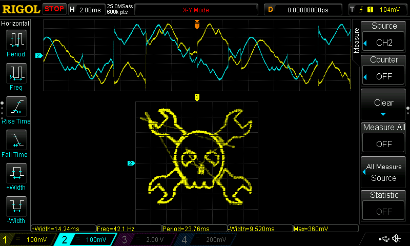
02/03/2018 at 14:18 • 9 commentsThere was a blog post about oscilloscope art from waveforms generated in Javascript recently. I made a wrencher.
![]()
You can display it on your own scope by hooking the left and right audio outputs from your soundcard (or smartphone, which is how I generated the image above - and photographed it at the same time!) to two oscilloscope inputs in X-Y mode. Here's a link to the jsfiddle which you can run directly.
The original idea and code to create audio and play it in JS come from Neil Fraser. You can find it on his blog.
I grabbed a wrencher bitmap I had around, and pasted it into xfig, an old-school vector drawing program that I can't unlearn, no matter how hard I try. I traced the outline of the wrencher parts with polylines in xfig, and saved the result. The fig file format is ASCII, so I was able to just cut and paste the points directly into JS. All the scaling and translation is done in the JS code so I could just use the points directly. You can probably paste pretty much anything in there, and it will do something, maybe.
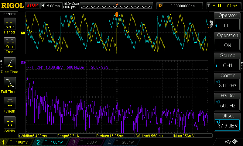
EDIT: @Thomas asked about a y-t view of the waveforms and the spectra. Here they are (not very instructive, it turns out):
![]()
![]()
I don't know how long jsfiddles live, so here's the code, too. Save it with an html extension, then open in your browser.
<html> <body> <input type="button" value="logo" onclick="had_logo()" /> </body> <script> function had_logo() { var points = [ [4752, 5407, 4757, 5131, 4832, 4847, 4859, 4808, 4974, 4617, 5139, 4444, 5214, 4390, 5409, 4266, 5684, 4200, 5884, 4222, 6141, 4297, 6292, 4386, 6417, 4510, 6528, 4652, 6634, 4816, 6710, 5052, 6736, 5300, 6705, 5584, 6656, 5735, 6550, 5948, 6479, 6050, 6369, 6151, 6301, 6210, 6341, 6285, 6301, 6436, 6150, 6507, 6031, 6463, 5955, 6379, 5964, 6285, 5920, 6276, 5920, 6374, 5866, 6445, 5769, 6503, 5627, 6467, 5556, 6387, 5547, 6281, 5529, 6276, 5511, 6387, 5445, 6472, 5338, 6507, 5232, 6467, 5165, 6365, 5161, 6237, 5181, 6203, 5171, 6195, 5118, 6139, 5121, 6143, 4961, 5979, 4868, 5806, 4823, 5722 ], [5070, 6205, 4721, 6525, 4717, 6738, 4633, 6924, 4455, 7080, 4269, 7133, 4100, 7133, 4038, 7115, 4384, 6809, 4025, 6410, 3674, 6711, 3661, 6560, 3723, 6352, 3834, 6201, 3985, 6121, 4193, 6077, 4357, 6094, 4766, 5762 ], [3683, 3778, 3683, 3769, 3670, 3893, 3696, 4071, 3789, 4217, 3923, 4346, 4136, 4408, 4357, 4395, 4791, 4761, 4797, 4754, 4859, 4648, 4926, 4532, 5123, 4342, 5134, 4333, 5098, 4301, 4717, 3951, 4717, 3898, 4721, 3782, 4677, 3658, 4593, 3525, 4477, 3423, 4357, 3370, 4167, 3356, 4056, 3374, 4380, 3676, 4020, 4075, 3683, 3778], [6701, 4737, 6607, 4612, 6536, 4488, 6368, 4346, 6346, 4336, 6763, 3960, 6776, 3756, 6838, 3600, 6954, 3463, 7140, 3374, 7286, 3356, 7428, 3370, 7105, 3671, 7464, 4080, 7806, 3782, 7819, 3862, 7815, 4018, 7699, 4235, 7539, 4359, 7375, 4417, 7247, 4421, 7118, 4404, 6713, 4750, 6701, 4737 ], [6088, 5043, 6257, 5034, 6377, 5123, 6448, 5225, 6452, 5367, 6430, 5500, 6355, 5566, 6284, 5606, 6257, 5509, 6159, 5438, 5999, 5358, 5928, 5273, 5920, 5149, 6017, 5078, 6070, 5047, 6088, 5043 ], [5737, 5591, 5720, 5611, 5671, 5731, 5658, 5850, 5662, 5926, 5711, 5850, 5755, 5802, 5791, 5864, 5818, 5930, 5840, 5864, 5822, 5731, 5782, 5620, 5756, 5589, 5737, 5591 ], [6439, 6205, 6559, 6068, 6674, 5890, 6727, 5753, 6734, 5744, 7140, 6094, 7286, 6072, 7460, 6090, 7615, 6188, 7739, 6316, 7819, 6503, 7815, 6698, 7477, 6414, 7100, 6809, 7451, 7115, 7344, 7146, 7087, 7115, 6896, 6973, 6763, 6738, 6767, 6521, 6430, 6218, 6439, 6205 ], [5321, 5022, 5431, 5038, 5542, 5114, 5578, 5229, 5542, 5327, 5391, 5416, 5276, 5455, 5232, 5504, 5227, 5602, 5152, 5602, 5041, 5469, 5019, 5309, 5063, 5167, 5174, 5065, 5303, 5025, 5321, 5022 ] ]; min = 10000; max = 0; for (var i = 0; i < points.length; i++) { segment = points[i]; for (var j = 0; j < segment.length; j++) { p = segment[j]; min = Math.min(min, p); max = Math.max(max, p); } } left = []; right = []; left.push(128); right.push(128); for (var k = 0; k < points.length; k++) { xy = points[k]; oldx = xy[0]; oldy = xy[1]; xy.push(oldx); xy.push(oldy); while (xy.length) { x = xy.shift(); y = xy.shift(); d = Math.sqrt((oldx - x) * (oldx - x) + (oldy - y) * (oldy - y)); n_pts = Math.floor(d /50) + 1; console.log(n_pts); for (var i = 0; i < n_pts; i++) { xp = oldx + (x - oldx) * (1.0*i / n_pts); yp = oldy + (y - oldy) * (1.0*i / n_pts); left.push(Math.max(Math.min(255 * (xp - min) / (max - min), 255), 0)); right.push(Math.max(Math.min(255 - 255 * (yp - min) / (max - min), 255), 0)); } oldx = x; oldy = y; } } left.push(128); right.push(128); left = left.concat(left); right = right.concat(right); left = left.concat(left); right = right.concat(right); left = left.concat(left); right = right.concat(right); left = left.concat(left); right = right.concat(right); left = left.concat(left); right = right.concat(right); left = left.concat(left); right = right.concat(right); console.log(left.length); var wav = makeWav(left, right); var audio = new Audio(); audio.src = 'data:audio/x-wav;base64,' + btoa(wav); audio.loop = true; audio.play(); } // from https://neil.fraser.name/news/2018/01/25/ function makeWav(left, right) { // Return a stereo WAV file built from the provided data arrays. var min = Math.min(left.length, right.length); var SubChunk2Size = min * 2; // RIFF chunk descriptor. var file = 'RIFF'; file += numToLong(36 + SubChunk2Size); // ChunkSize file += 'WAVE'; // The 'fmt ' sub-chunk. file += 'fmt '; file += numToLong(16); // Subchunk1Size file += numToShort(1); // AudioFormat file += numToShort(2); // NumChannels file += numToLong(48000); // SampleRate file += numToLong(48000 * 2); // ByteRate file += numToShort(2); // BlockAlign file += numToShort(8); // BitsPerSample // The 'data' sub-chunk. file += 'data'; file += numToLong(SubChunk2Size); for (var i = 0; i < min; i++) { file += numToChar(left[i]) + numToChar(right[i]); } return file; } function numToChar(num) { // num is 0 - 255 return String.fromCharCode(num); } function numToShort(num) { // num is 0 - 65536 var b0 = num % 256; // low var b1 = (num - b0) / 256; // high return String.fromCharCode(b0) + String.fromCharCode(b1); } function numToLong(num) { // num is 0 - 4.2billion var b0 = num % 256; num = (num - b0) / 256; var b1 = num % 256; num = (num - b1) / 256; var b2 = num % 256; num = (num - b2) / 256; var b3 = num; return String.fromCharCode(b0) + String.fromCharCode(b1) + String.fromCharCode(b2) + String.fromCharCode(b3); } </script> </html> -
Finally FPGA!
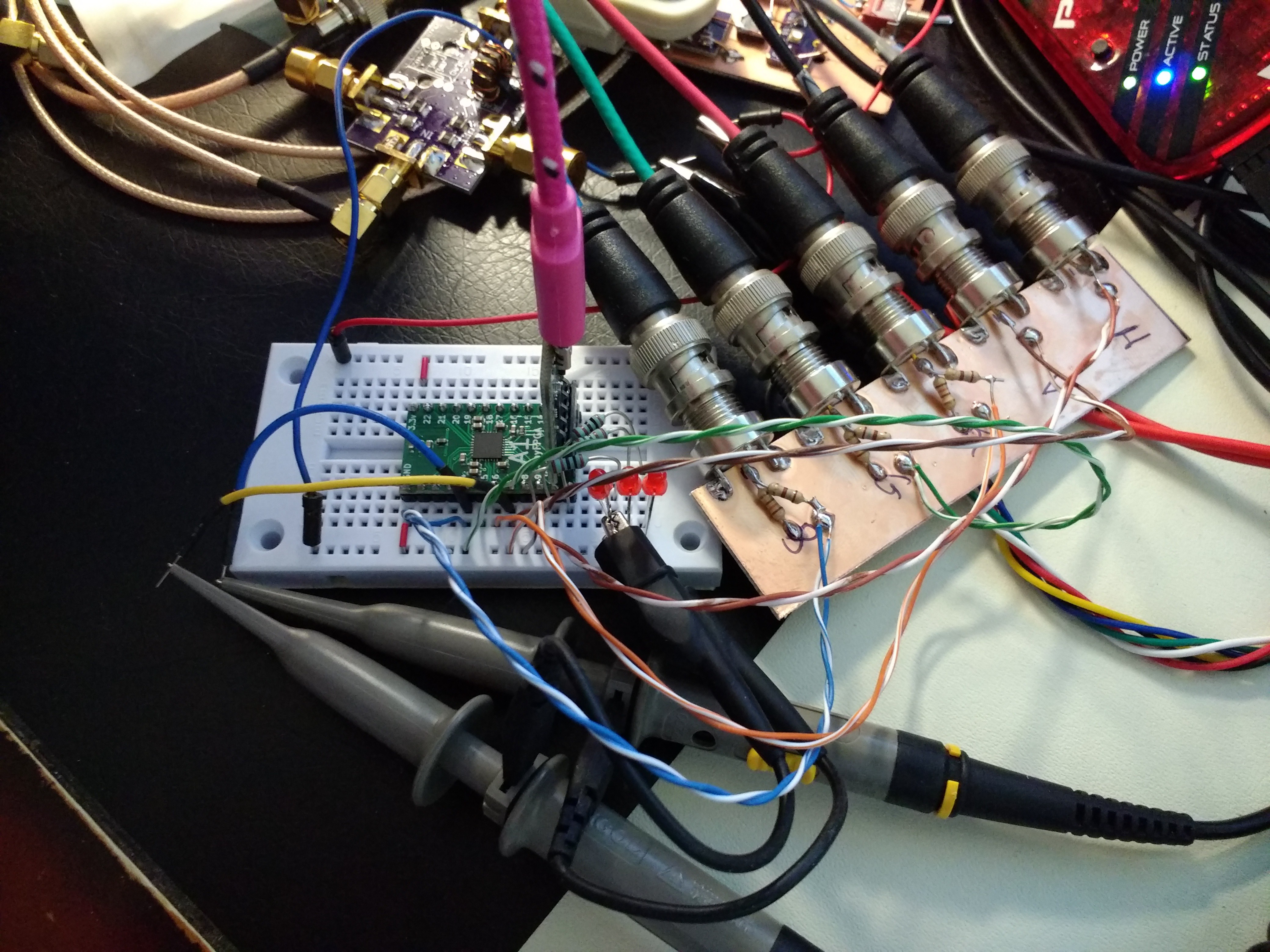
01/27/2018 at 20:49 • 2 commentsI wanted to get started with FPGAs for a long time. Today, it finally happened. I bought a #TinyFPGA A-Series (A1 specifically) on Tindie, and started coding. After a few hours, I came up with a bouncing ball on a VGA monitor (starting from scratch).
I know there are simple VGA examples out there, but I resisted looking at them for the exercise. It's not super-complex, but a lot of things have to be right to get this to work. There are a few issues, mainly about the clock. I used the internal clock source on the FPGA, which isn't very accurate or stable. Additionally, the closest I could get to the proper 25.175 MHz dot clock was 24.18 MHz. The result is a little jitter on the display. I could solve this with an external oscillator, but this was just an exercise.
The hardware is simply the A1 board and six resistors to shift the RGB levels and provide a proper 75-ohm output impedance. I didn't have any VGA connectors around, so I used BNC's and an old-school VGA-to-BNC cable. There are a few in-progress projects in the picture, but you can locate the TinyFPGA and the BNCs. The three LEDs from the example in the TinyFPGA documentation are still in the breadboard :-)
![]()
The verilog code could probably be prettied up a lot, but at this point, I'm just excited to have something going. This is sure to give experienced RTL jockeys a good laugh:
module TinyFPGA_A1 (
  output pin4_mosi,
  output pin5,
  output pin6,
  output pin7_done,
  output pin8_pgmn
                    );

  wire clk;
   OSCH #(.NOM_FREQ("24.18") // should be 25.175 - close enough!
          ) internal_oscillator_inst (
                                      .STDBY(1'b0),
                                      .OSC(clk)
                                      );

   parameter ball_size = 20;
   reg [9:0] horiz_ctr;
   reg       hsync;
   reg [9:0] vert_ctr;
   reg       vsync;
   reg       hblank;
   reg       vblank;
   reg [9:0] row;
   reg [9:0] col;
   reg       dr;
   reg       dc;
   reg [2:0] rgb;
   always @(posedge clk) begin
      horiz_ctr <= horiz_ctr + 1;
      if (((vert_ctr-45) >= row) &&
          ((vert_ctr-45) <= (row+ball_size)) &&
          ((horiz_ctr-160) >= col) &&
          ((horiz_ctr-160) <= (col+ball_size)))
        rgb = 3'b100;
      else
        rgb = 3'b001;

      case (horiz_ctr)
        10'd16:  hsync <= 1;
        10'd112: hsync <= 0;
        10'd160: hblank <= 0;
        10'd800:
          begin
             horiz_ctr <= 0;
             hblank <= 1;
             vert_ctr <= vert_ctr + 1;
             case (vert_ctr)
               10'd10:  vsync <= 1;
               10'd12:  vsync <= 0;
               10'd45:  vblank <= 0;
               10'd525:
                 begin
                    vert_ctr <= 0;
                    vblank <= 1;
                    if (dr)
                      row <= row + 1;
                    else
                      row <= row - 1;
                    if (dc)
                      col <= col + 1;
                    else
                      col <= col - 1;
                    if (row < 1) begin
                       row <= 1;
                       dr <= ~dr;
                    end
                    if (col < 1) begin
                       col <= 1;
                       dc <= ~dc;
                    end
                    if (row > (479-ball_size)) begin
                       row <= 479-ball_size;
                       dr <= ~dr;
                    end
                    if (col > (639-ball_size)) begin
                       col <= 639-ball_size;
                       dc <= ~dc;
                    end
                 end
             endcase
          end
      endcase
   end

   wire frame_active = !vblank & !hblank;

   assign pin8_pgmn = !hsync;
   assign pin7_done = !vsync;
   assign pin4_mosi = frame_active & rgb[0];
   assign pin5 = frame_active & rgb[1];
   assign pin6 = frame_active & rgb[2];
endmodule
If I'm reading the output of the Lattice Diamond software correctly (doubtful), I've used 117 of the 256 available LUT's - less than half. I didn't think about optimizing the code at all - at this point, I wouldn't know exactly where to start.
I am really impressed with how easy this all is. Kudos to @Luke Valenty on a very nice project/product.
-
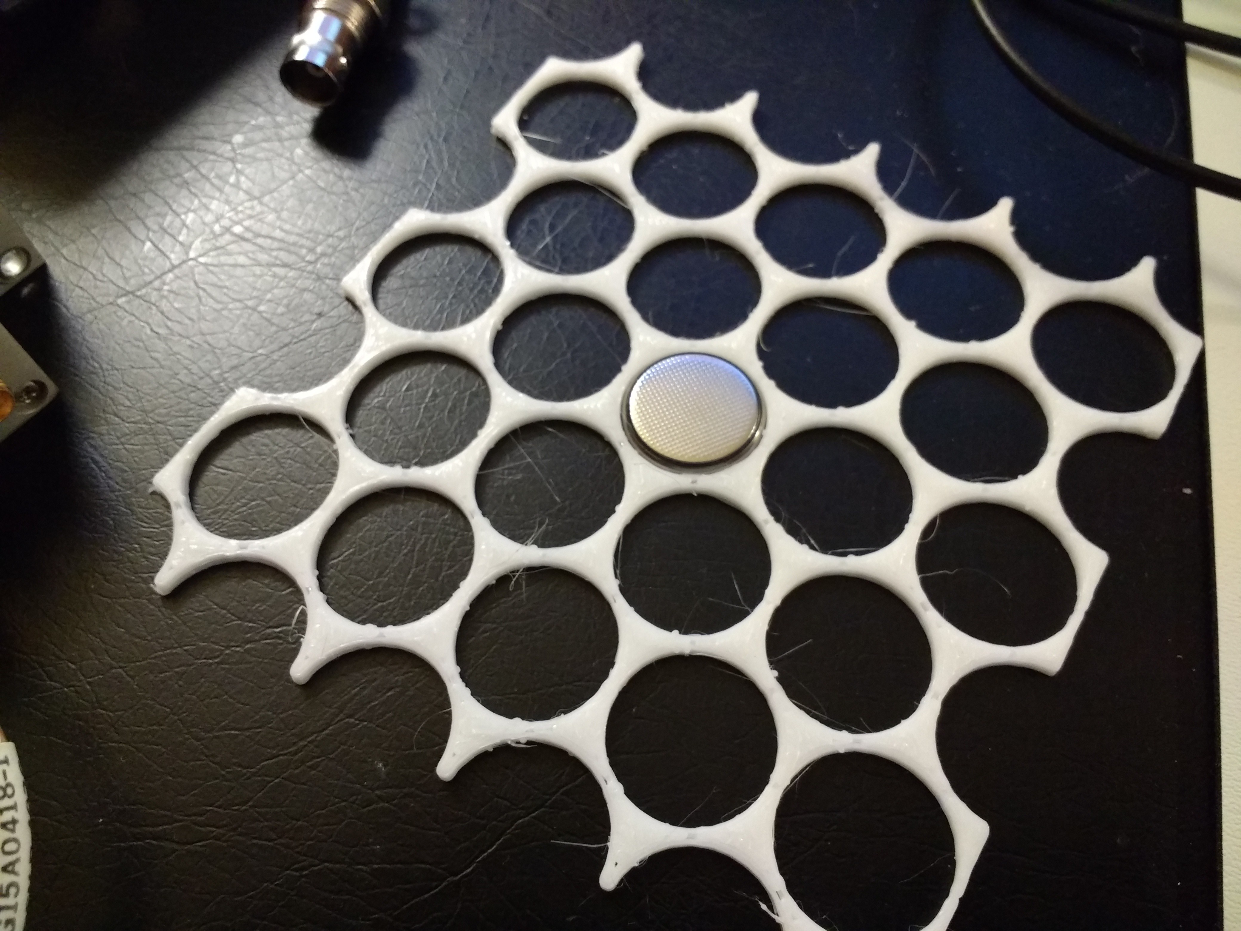
Honeycombs everywhere
01/12/2018 at 04:49 • 0 commentsEvery few months I decide I need to use a honeycomb-type arrangement of something-or-other. Today it was holes to fit a bunch of CR2032 cells. I usually grab a piece of paper and figure out the spacing all over again - I know I have a dozen or more programs in various languages that do it, but I never can seem to find one, so I decided to document it here. Maybe mostly for me :-)
![]()
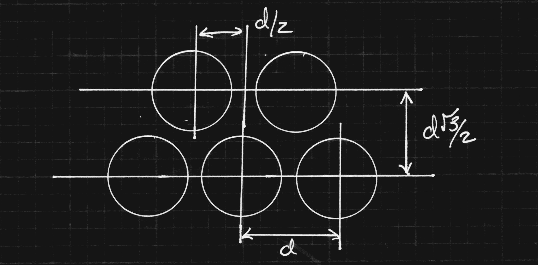
If you remember one thing, it's that the row spacing is sqrt(3)/2 * the column spacing. Every other row is offset by 1/2 the column spacing, which causes the staggering of adjacent rows. A diagram is easier to visualize:
![]()
Using this, it's pretty easy to perforate a flat sheet with honeycombed holes in OpenSCAD:
// coin cell honeycomb separator cell_dia = 20.5; thickness = 2.0; dx = 22; length = 5*dx; width = 3*sqrt(3)*dx; epsilon = 0.1; module spacer(){ difference(){ translate([-length/2, -width/2, 0]){ cube([length, width, thickness]); } for (i = [-5:5]){ for (j = [-5:5]){ x = dx * i - dx * (j % 2) / 2; y = dx * (sqrt(3)/2 * j); translate([x, y, -epsilon]){ cylinder(d = cell_dia, h = thickness + 2*epsilon); } } } } } spacer(); %translate([length, 0, 0]) spacer(); %translate([0, width, 0]) spacer(); %translate([length, width, 0]) spacer(); -
Is the dishwasher clean?
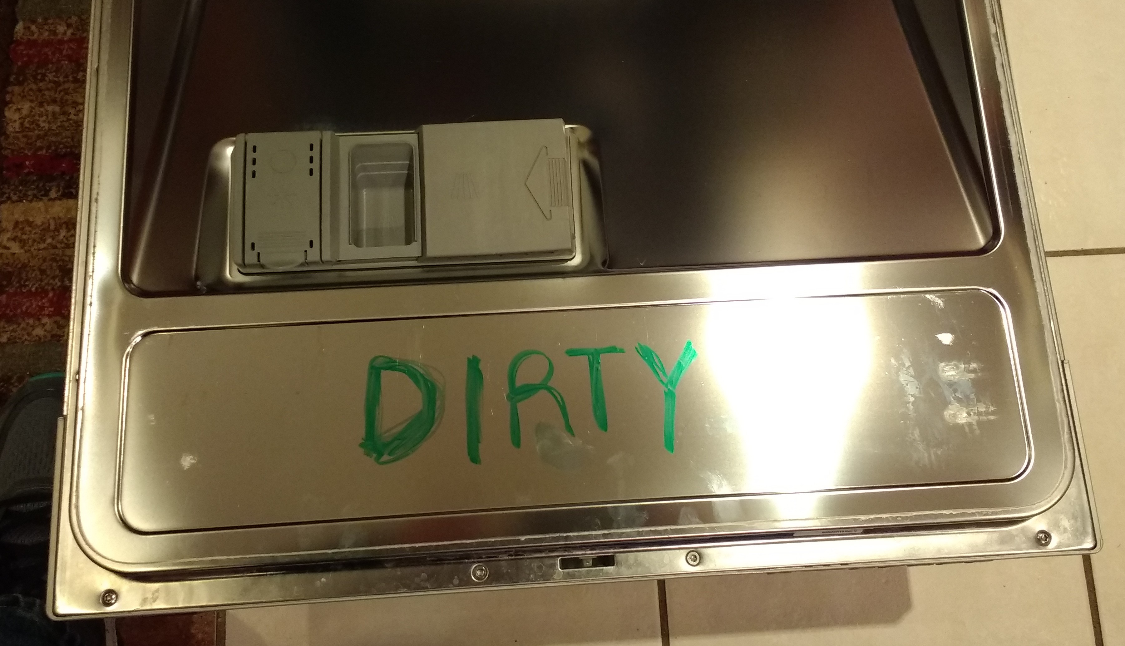
01/08/2018 at 01:58 • 2 commentsI do the household chores, and I used to get asked several times a day if the dishes in the dishwasher were clean. Now, whenever I empty it and put away the clean dishes, I write the word "DIRTY" inside the door with a washable marker:
![]()
The word remains as dirty dishes are loaded throughout the day, but automatically disappears whenever you run the machine.
-
Getting straight header pins
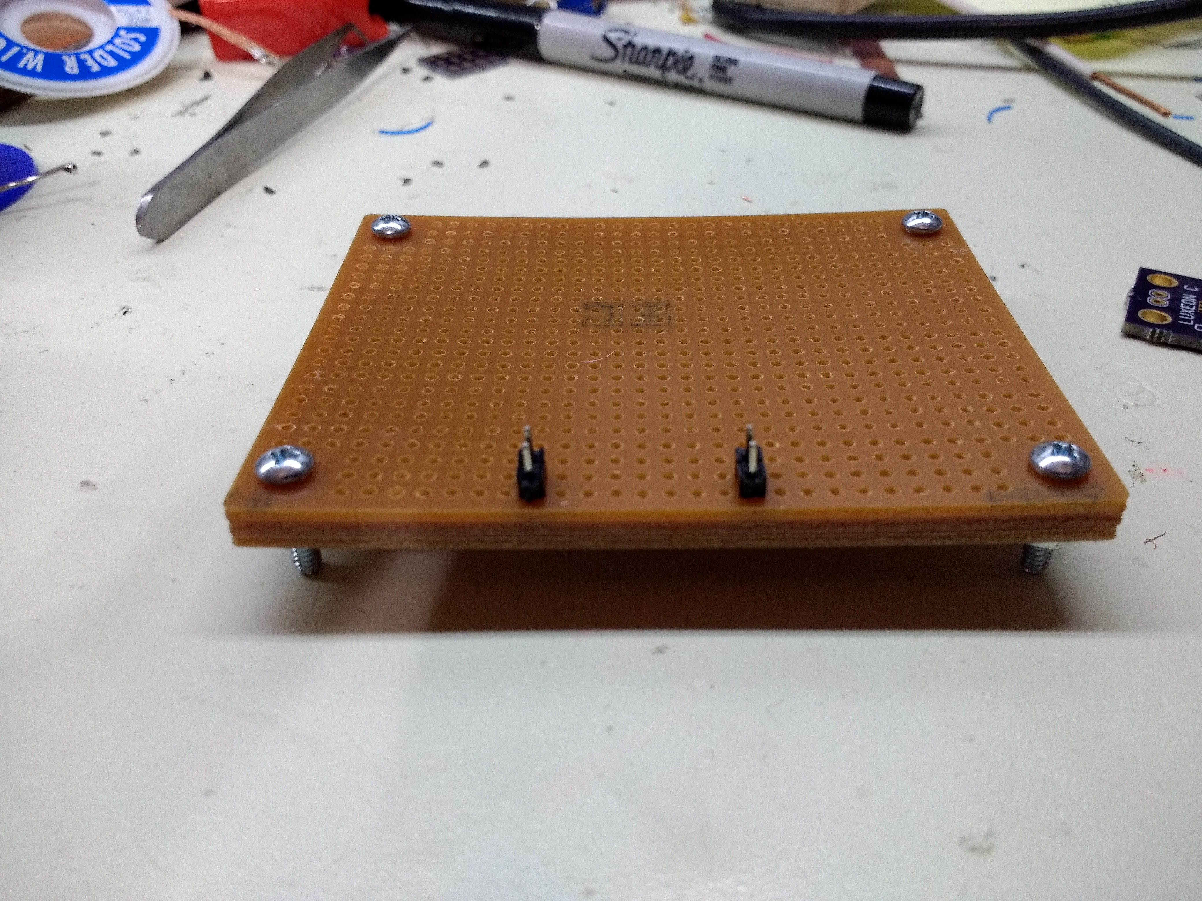
12/28/2017 at 17:05 • 0 commentsCrooked header pins bother me. I've started using a stack of cheap perfboards to align them for soldering. Nuts and bolts in the mounting holes keep the boards aligned:
![]()
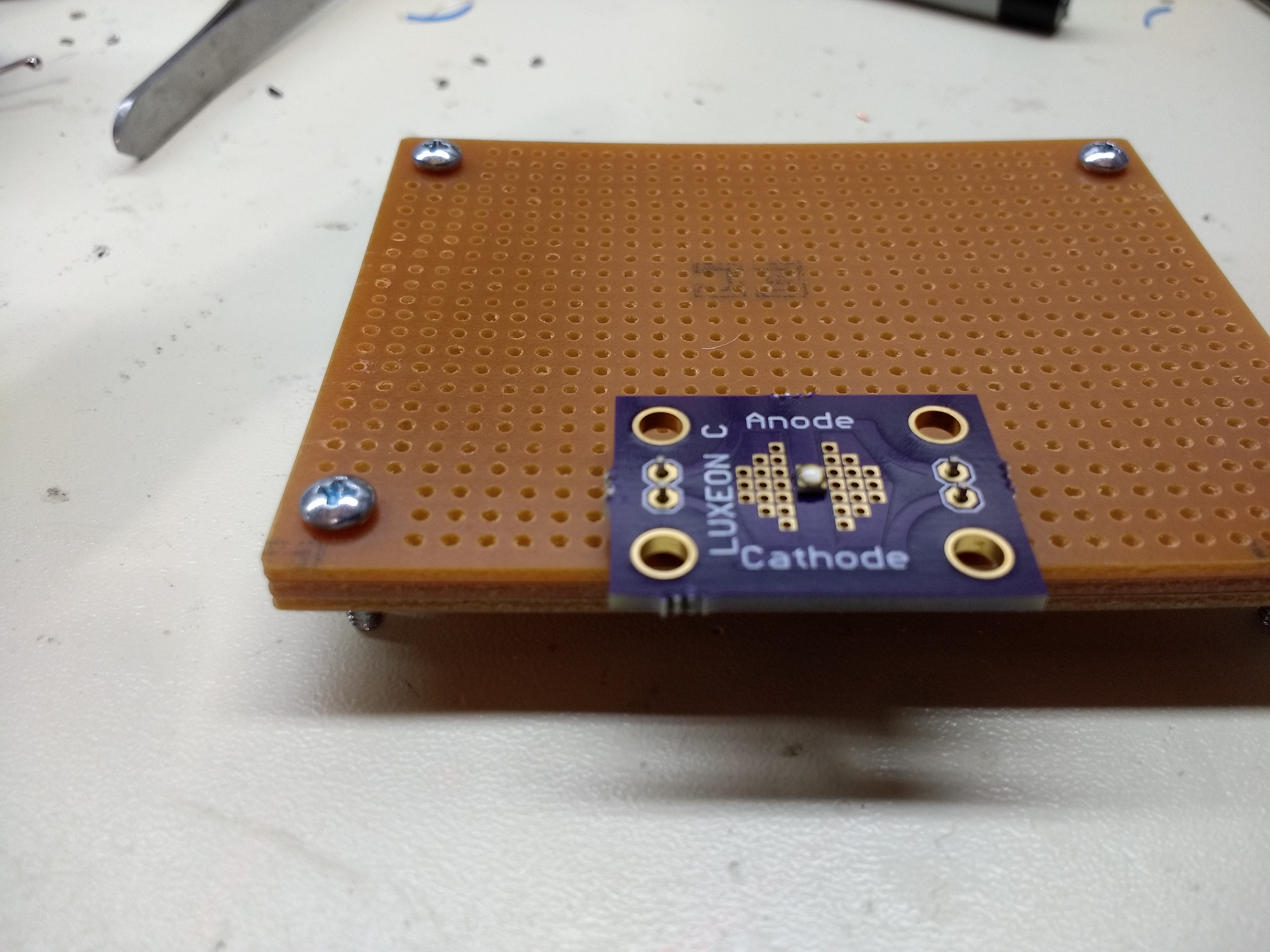
Once the pins are in place, the target board can be set on top, and the pins soldered:
![]()