-
1Manufacturing the PCB
When I design a layout in Eagle, I like to print it out on regular paper, to see the design in real life and to check the sapcing of the components. You can see a few versions here:
![]()
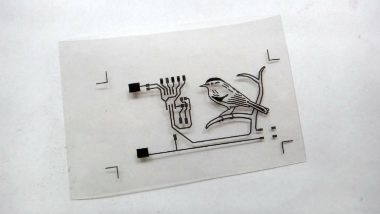
Then I printed the final design on transparent film.
![]()
This was the first time I used my selfmade UV exposure box, so in order to minimize the possibility of a failure, I used a single layer PCB which had preapplied photoresist.
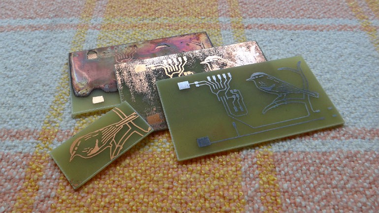
Unfortunately I also switched chemicals and I didn't have a proper scale to measure the quantities so I had many-many failures before getting a decent board.
![]()
I used a chemical tinning solution to make the traces and the image of the bird shiny and corrosion resistant.
-
2Populating the board
There's only two tricks in soldering the components:
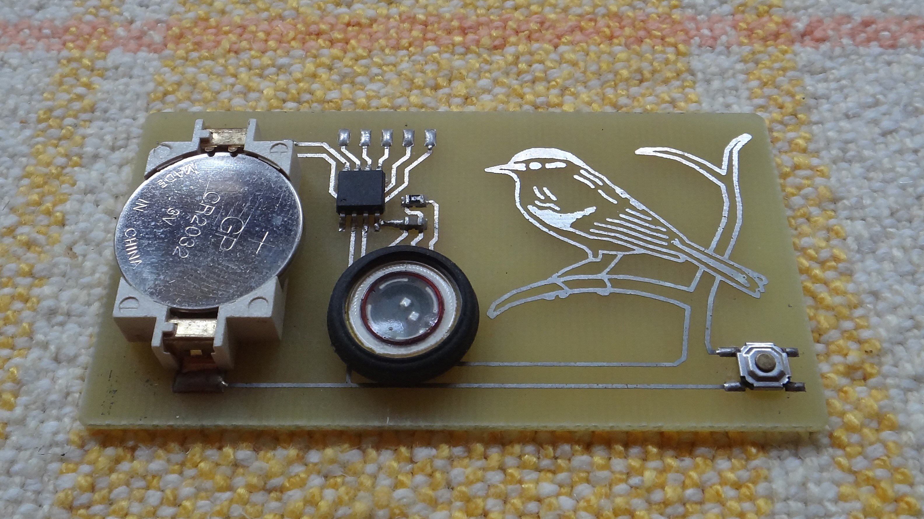
- There must be a wire connection between "PAD1" and "SPK2" underneath the speaker. (I didn't want to have two layers just for this connection)
![]()
- The speaker is also connected using small pieces of wires. I found that using a silicon based glue makes a good, flexible fixation for the speaker.
- There must be a wire connection between "PAD1" and "SPK2" underneath the speaker. (I didn't want to have two layers just for this connection)
-
3Programming the board
Some wires with an ISP connector must be soldered to the top pads temporarly. You need to have the coin cell already installed during programming! After uploading the program and desoldering the wires the board is fully functional.
The microcontroller is always powered, but sleeping most of the time. It only wakes up when the button is pressed and it goes back to sleep immediately after the song is finished.
![]()


Discussions
Become a Hackaday.io Member
Create an account to leave a comment. Already have an account? Log In.