Keith
Keith-
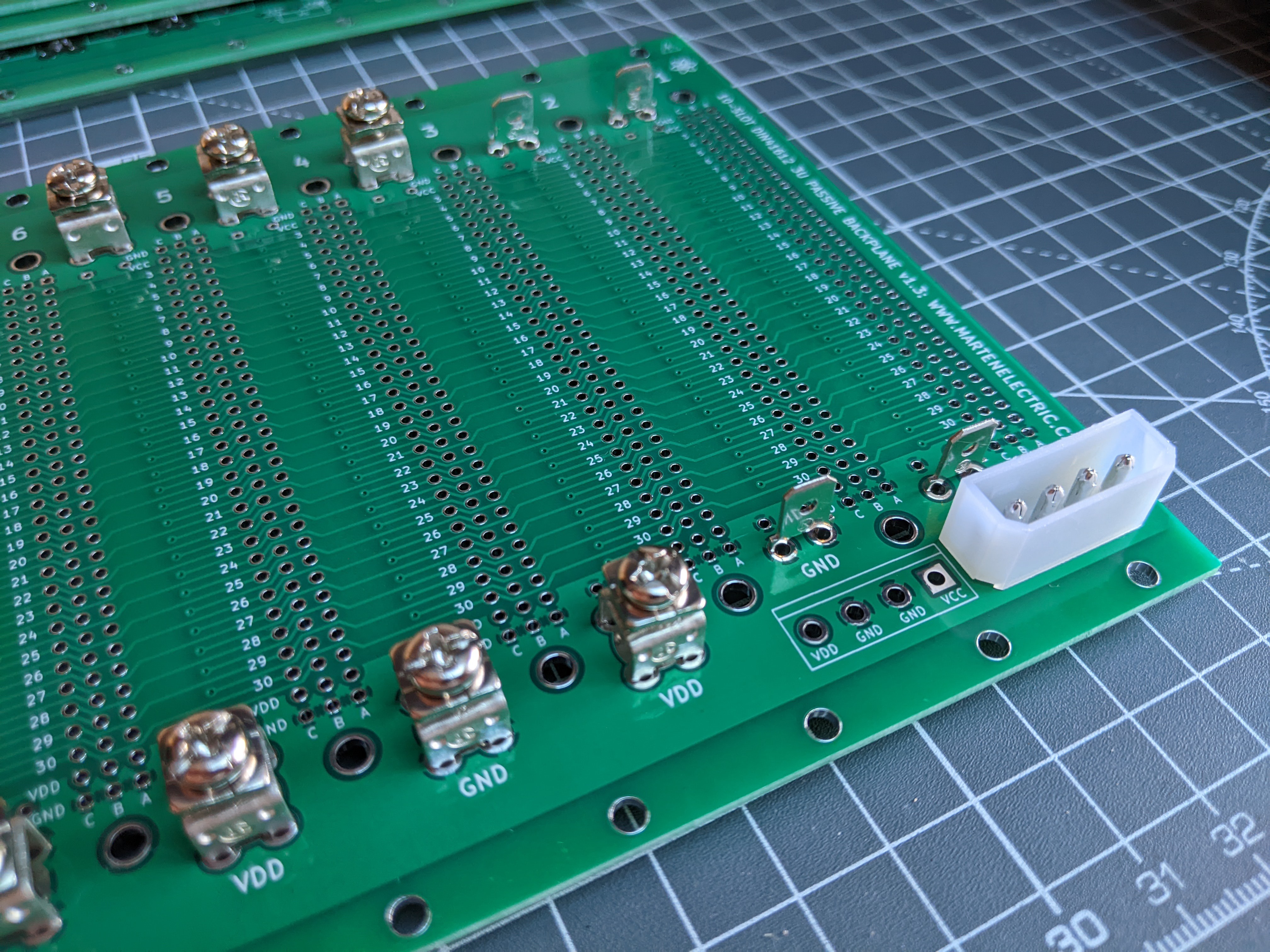
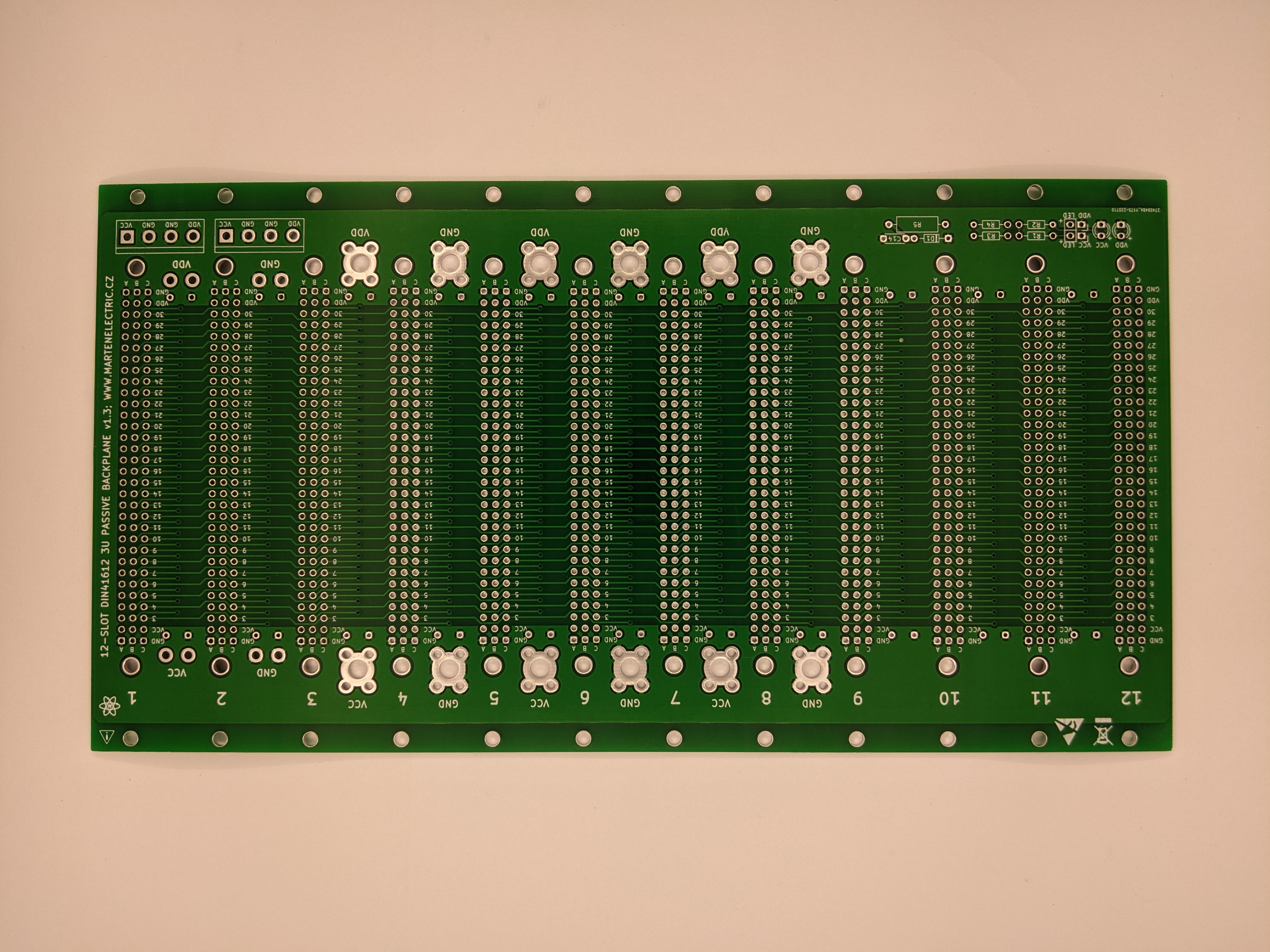
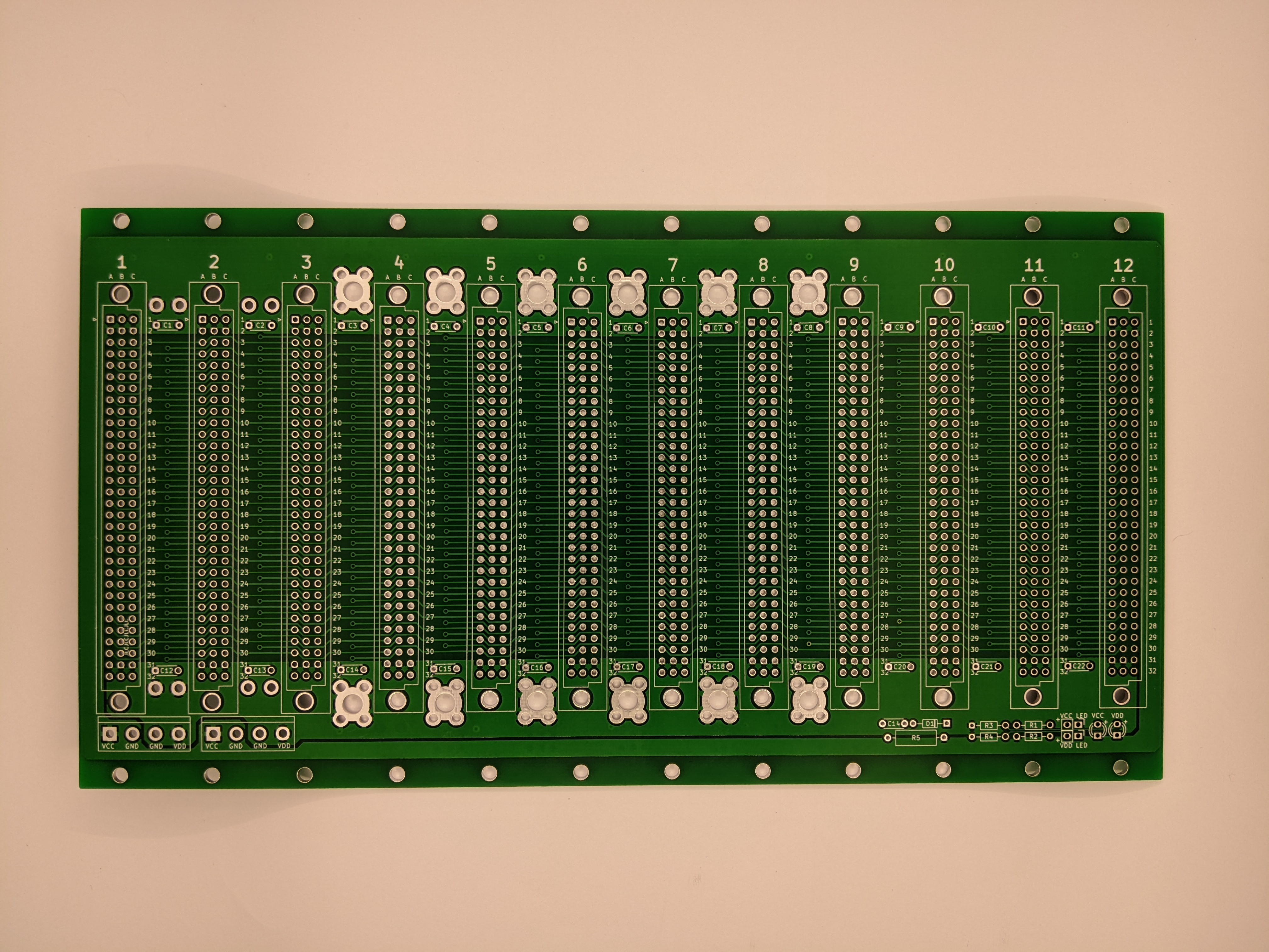
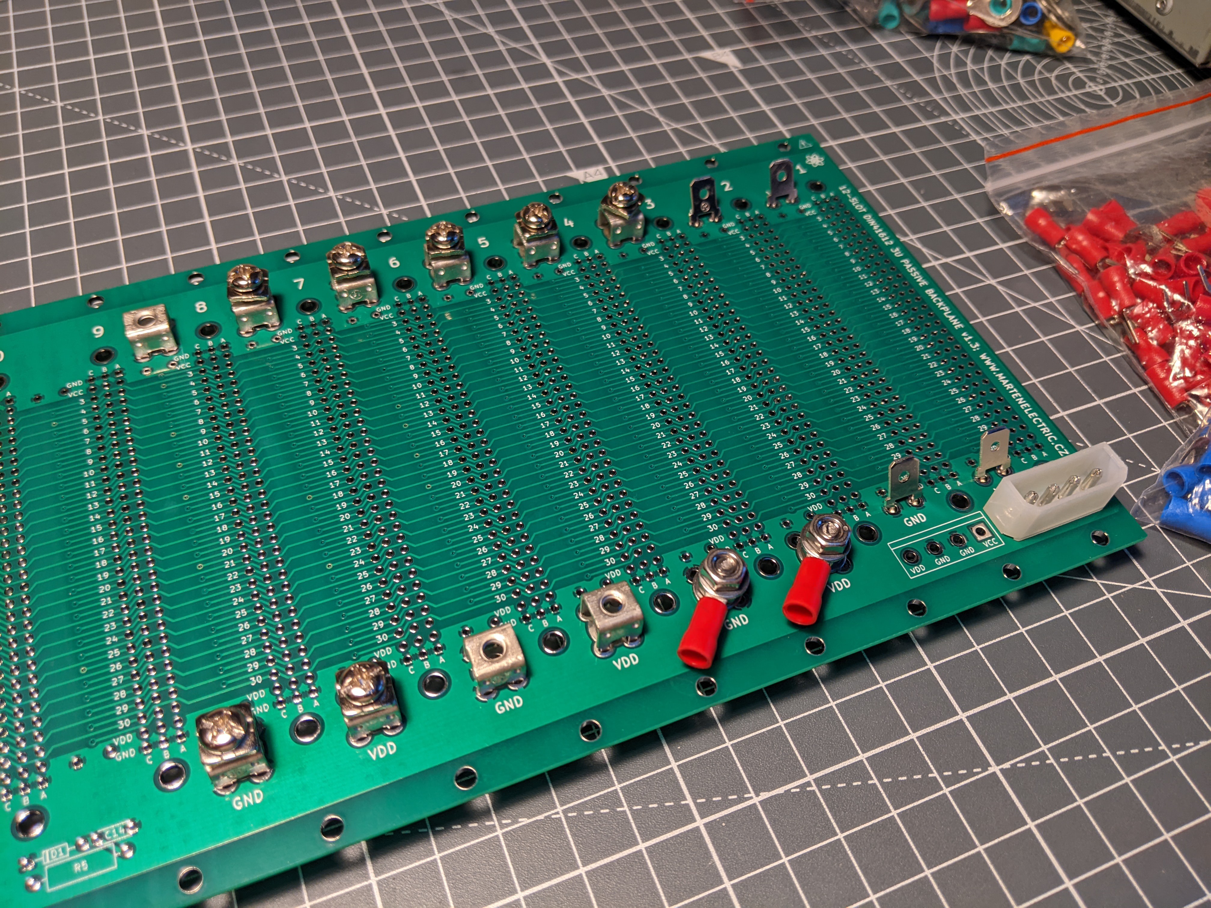
Martin Niec's backplane designs
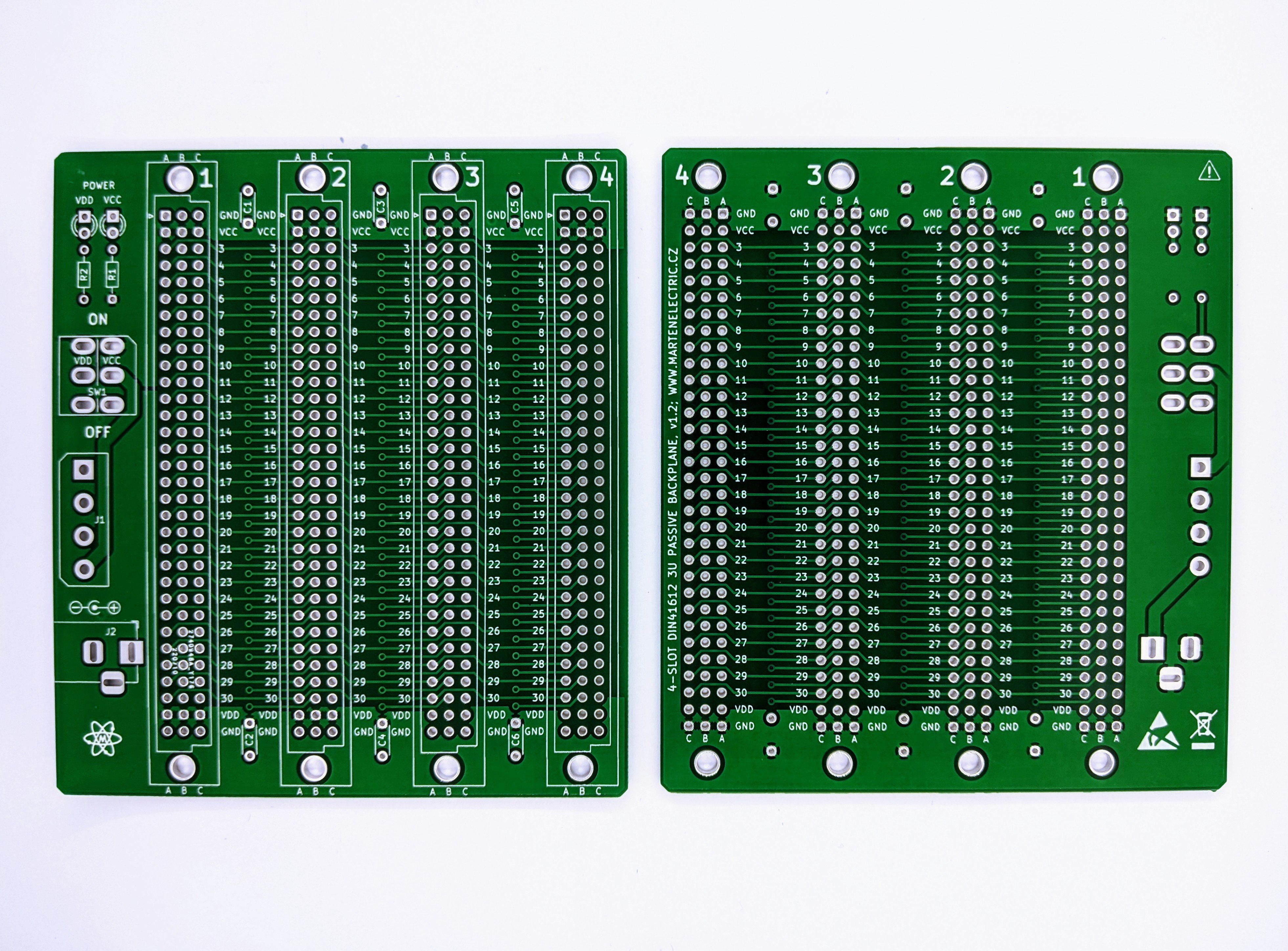
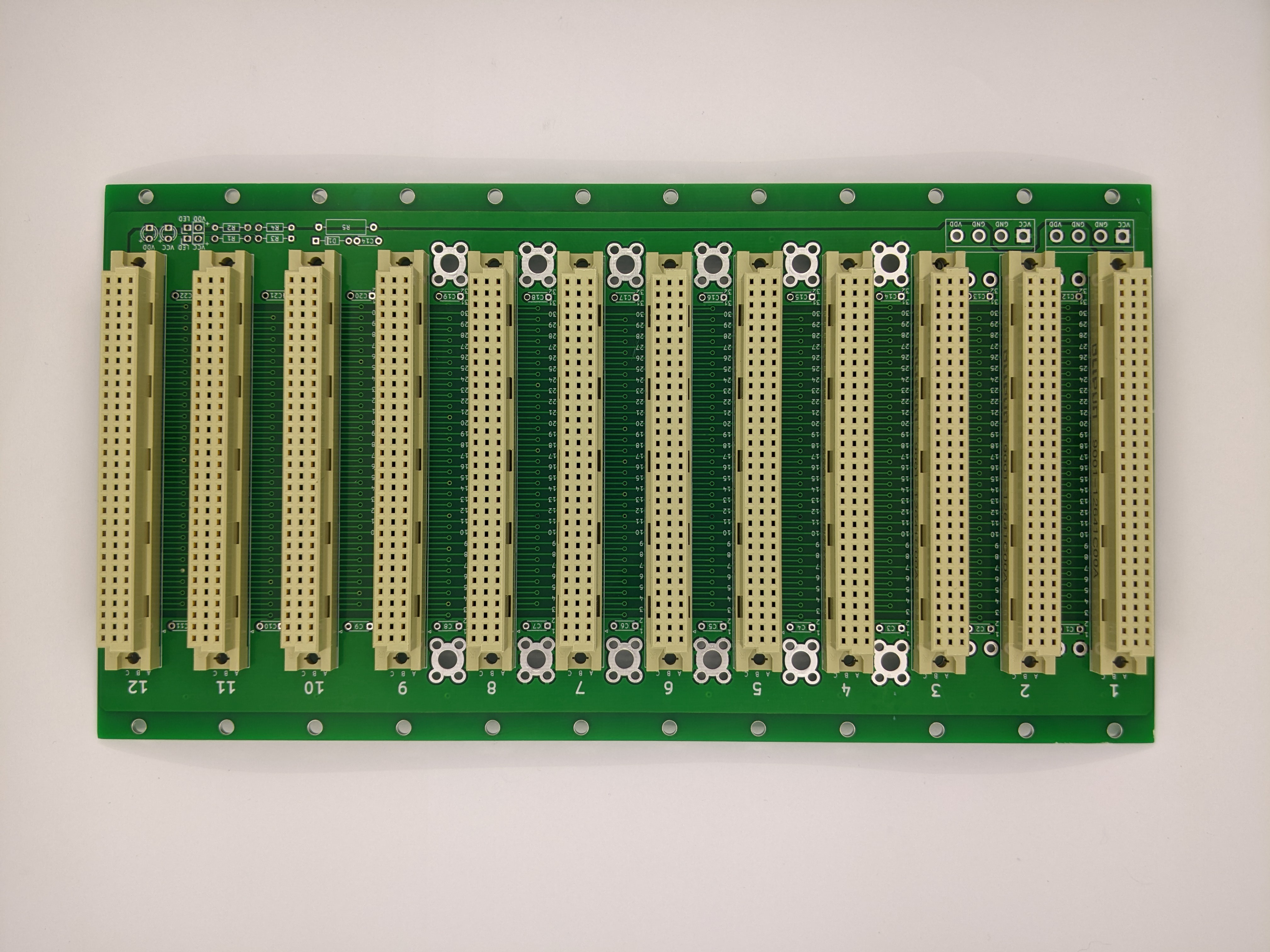
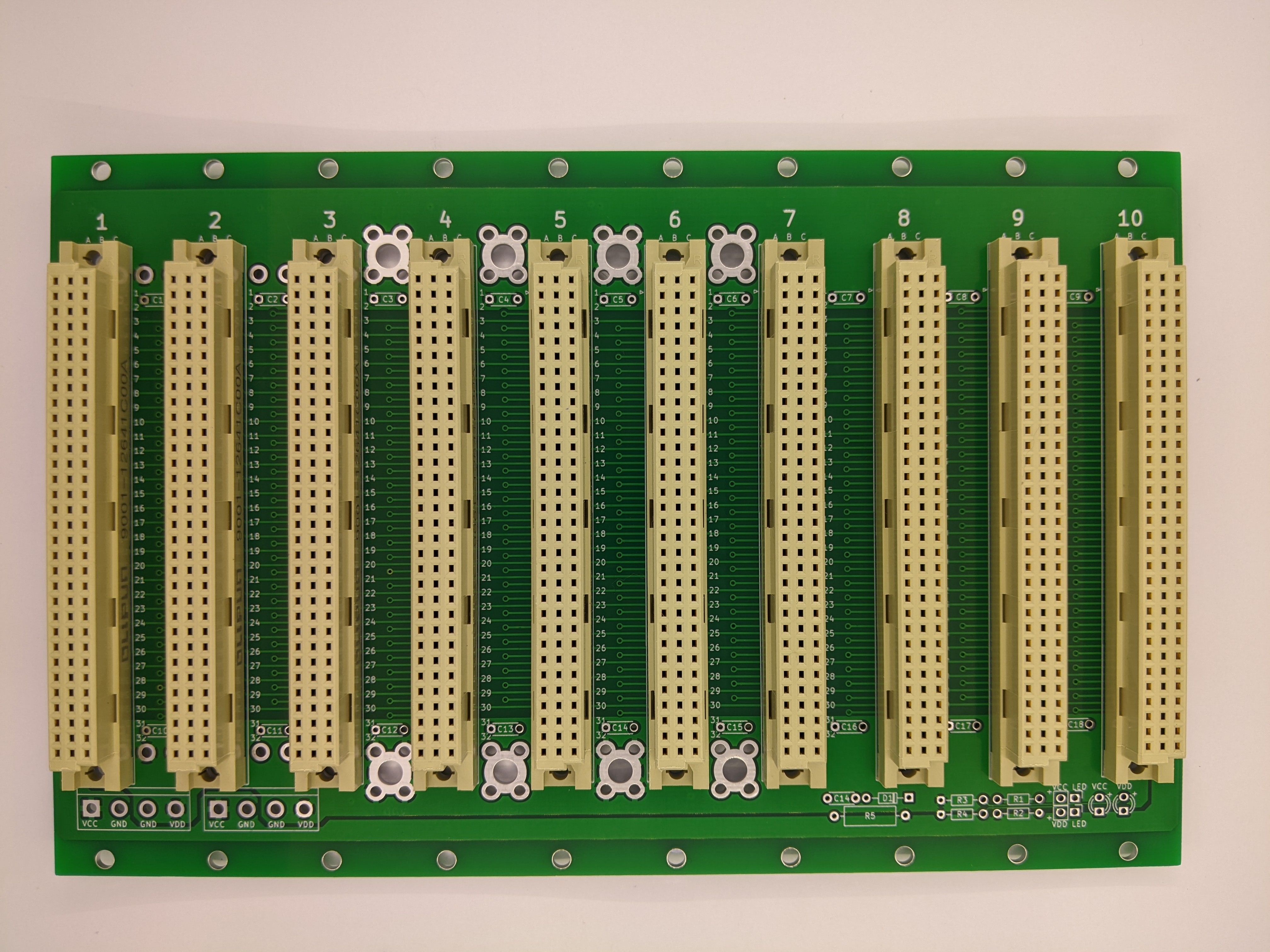
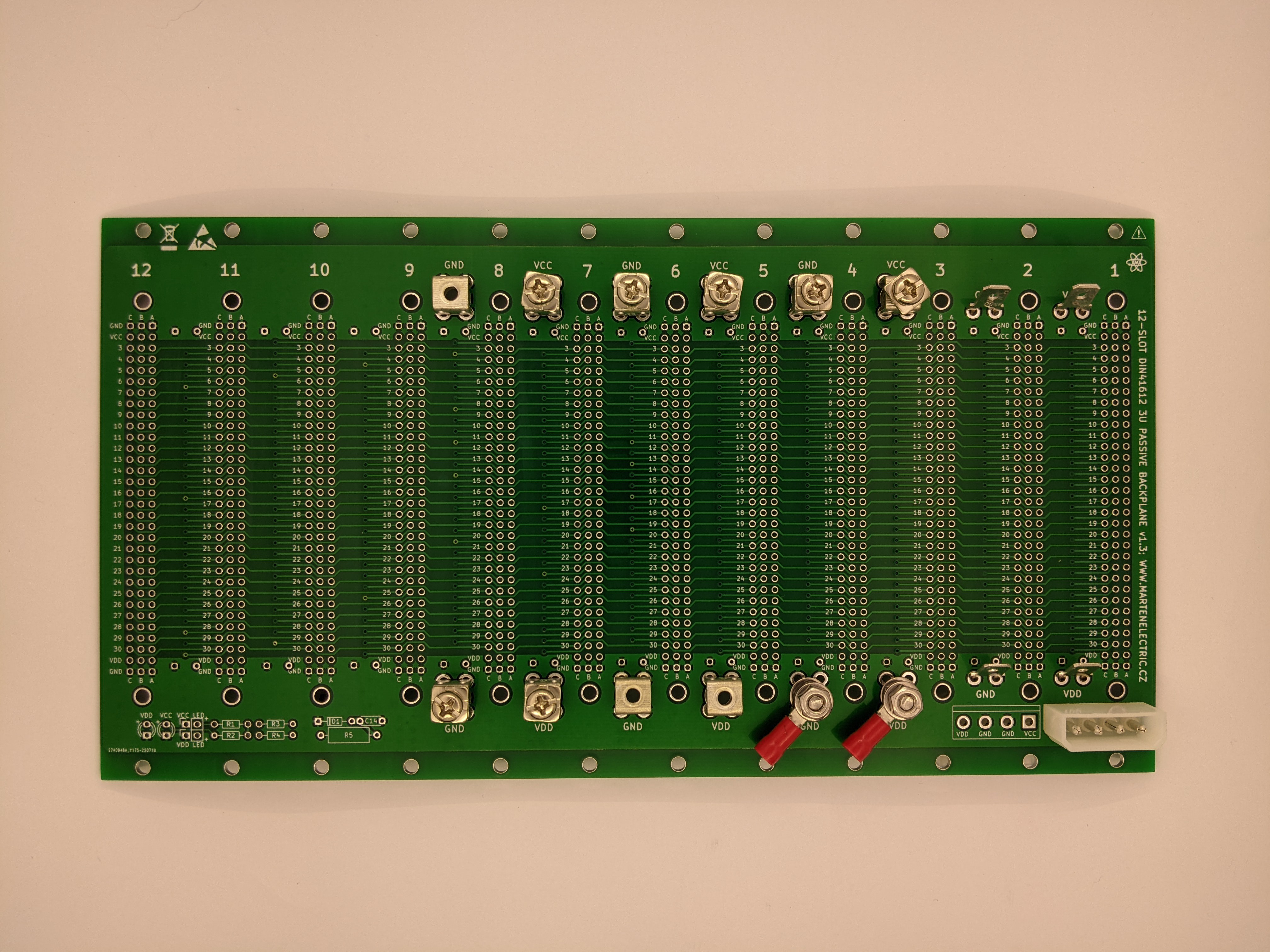
05/27/2023 at 20:08 • 0 commentsIn 2022, Martin Niec sent me some pictures of some STEbus backplanes he was making.
These omit terminations, as he wanted them to be usable in other buses (so long as they share the same power and ground pins, which will exclude VMEbus P1 and ECB bus boards).
The ground and power rails are fixed at the edge-most pins. This allows large current-carrying copper lands.
![]()
For more than a few slots, current consumption may be large, so plenty of power connections are advisable.
![]()
![]()
![]()
![]()
![]()
![]()
![]()
-
Wireless-World 1989-11 STE Standard Eurocard bus article by Anthony Winter
12/31/2022 at 00:22 • 0 commentsSTE
Standard Eurocard busApplications of Standard Eurocard bus range from simple control to multi-processor systems and all boards are interchangeable.
ANTHONY WINTER
In low-to-medium complexity designs, STE bus suits the kinds of applications that buses like STD are currently used for, but with performance, security and cost advantages.
Being based on the DIN connector and Eurocard, STE can be used with other buses to form relatively low cost multiple-bus systems. And, in relation to edge connectors, the DIN connector is more reliable.
Although designed for eight-bit data buses STE can be used with the latest generation of 8/16-bit processors. The bus was first specified in 1982, and the first boards were available in mid 1984. Since then, it has been widely adopted by board manufacturers. There are now hundreds of processor, peripheral and signal-conditioning modules. Moreover STE is a standard backplane bus and so you can mix boards from any sources.
Processing units now available span a broad application range, with microprocessors from the popular Z80 to newer and more powerful devices like the 80188, Fig.1. In the UK so far, STE has an estimated 100 users and at least 18 companies manufacturing boards, backplanes and packaging. Applications range from software development, through real-time control, to laboratory computing.
BUSES ARE CHANGING
As more complex VLSI circuits become available, backplane buses have grown in importance helped by their recent improvements in quality. Most growth is in the high-performance 16-bit buses such as VME and Multibus-II, which include advanced features and are based on the Eurocard standard and DIN connector.
If you are looking for a standard at lower performance levels, however, choice is limited. Two current popular choices, STD and S100, are edge-connector based, with outdated signal schemes originally designed for a single 8-bit processor family. Although they have been modified to take account of more advanced processors and large memories, the patches are showing.
The situation is similar with Eurocards. There are dozens of single-Eurocard buses but almost all are designed for a single processor family and intended for simple one-processor systems. Here, none has emerged as a standard with worldwide use and support.
A typical example is G64, which uses Motorola 6809 signals. The G64 bus has now been 'enhanced' to cope with other processors, often at the expense of compatibility with earlier designs.
STE was originally conceived as a Eurocard replacement for STD. It is similar to VME, and can be viewed as an 8-bit version of that standard but, unlike VME, STE has been designed from scratch to be an independent bus, suitable for a broad range of processors and tasks.
BUS ATTRIBUTES
The STE signal scheme may be summarized as an eight-bit data path, with 1M-byte of memory space, 4K-bytes of i/o space, asynchronous data transfer, board positionindependence, multiple master capability and inter-module flags for interrupts or DMA Using Eurocard form boards with 64-way (rows A/C) DIN connectors makes STE reliable.
An eight-bit data path is used, but this is not a disadvantage. There are already good bus standards for 16-bit data paths like VME but ther is no standard eight-bit Eurocard bus. Also, STE goes beyond most existing eight-bit buses in two respects. First, it can accommodate the latest generation of eight-bit processors, and of course, most 16-bit processors are also made in eight-bit versions. Secondly, the bus has multiple-master capability; up to three processors may work in a system. Another point worth noting is that almost' all peripheral i.c.s are designed for eight-bit operation.
The bus is equally at home in simple systems with a single processor and a few expansion modules. Used as a vehicle for systems using familiar and popular processors like the Z80, it suits applications for which STD is currently being used.
Another advantage of STE over STD is the expansion potential given by the Eurocard packaging. The bus can be used alongside VME as a low-cost i/o channel for instance, or as a local bus for processing.
Many systems are hampered by the restricted addressing ranges of earlier buses, which were generally designed around processors limited to 64K-byte. STE provides two separate addressing fields; 4K-byte of i/o locations and a 1M-byte memory addressing space.
Processors like the Z80 can switch the top four address lines with a latch. This form of bank switching is used to advantage in operating systems like CP/M-plus, which uses this extra memory to speed up disc operations by a significant amount.
Input/output capability is similarly large. Twelve i/o address lines provide 4096 i/o locations, enough for most conceivable small-to-medium systems. Processors with no i/o space, like the 6809 or 68008, can set aside a 4K memory block for bus i/o accesses.
A significant problem with nearly all buses is their inability to work with boards designed later in the standard's life. This is primarily because most buses use synchronous operation.
Data from a peripheral board, for example, must be available to the CPU within the defined time. Processor speeds are currently doubling every four or five years, and peripherals may not be able to keep up.
To overcome this lifetime limitation, STE uses asynchronous handshaking. For example, slave boards need to acknowledge that they've received data from a master. This has two main advantages. It makes it easy to interface devices of differing speeds, and provides technology independence. As better devices become available, they will still work with boards based on earlier technology.
STE compared with other popular backplane buses.
Feature STE STD G64 Signal lines 64 56 64 Address range 1MB 64K 64K Data path 8-bit 8-bit 8-bit I/O space 4K 256 byte 1K Multiple masters up to 3 off-bus connection required yes Error checking error line none yes Primary board size 100x160mm 114x165mm 100x160mm Connector DIN Edge DIN CONFIGURING STE
Users of only modest experience should be able to assemble systems successfully. STE is free from 'levels of compliance' which means that all boards are compatible with all other boards and no slots are reserved. Boards are truly position-independent.
Another feature is STE's multiple processor; or multi-master ability. Up to three processors may reside on the bus, taking control of the common bus resource after going through an arbitration procedure.
Typically, masters are CPU boards and DMA devices. A bus slave must be able to respond to bus signals to produce an acknowledge signal when addressed.
The bus is used for communicating between boards, for example to transfer data or handle interrupts. Often, if there is enough circuitry on one board, a master can do its processing locally, freeing the STE bus for other masters to use.
For example, the Arcom SC88D board includes an 80188 processor, 256K-byte ram, and serial i/o. It only needs to use the bus to program an eprom or, say, read a value from an a-to-d converter module. Simultaneously (within a microsecond or so) another CPU could be processing the converter values stored in ram on a common memory board.
Using multiple processors allows highly fault-tolerant designs to be made or reduces the cost of high-performance systems by allowing several simple low-cost masters to take the place of an expensive state-of-the-art CPU board.
The STE specification permits up to three bus masters, one default and two others termed 'potential'. A default master is a board with a bus arbiter and a master, for example a CPU The bus arbiter deals with requests from the master on its own board and from any other potential masters in the system.
DATA TRANSFER
An important feature of STE is asynchronous operation which increases a system's useful lifetime by allowing mixing of devices of different generations and operations speeds for example. An example of a read operating illustrates how this works in practice. Data transfers from a slave to a master are designated read sequences. First, the master places the address of the memory or i/o location to be selected on the address lines. After a set-up time, during which the address lines become valid, the master asserts the address strobe ADRSTB*. The master then activates the command lines to indicate the type of transfer, i/o or memory read, asserting DATSTB* after an appropriate set-up time, thus indicating that it is ready to accept data. The addressed slave now enables its bus drivers, placing the requested data on the data lines, then asserts DATACK* after a set-up time to indicate that data is available. In response to this signal, the master accepts the data and then releases ADRSTB* and DATSTB*. When the slave sees this operation, it disables its data bus drivers and releases DATACK* to indicate a completed sequence. No time restrictions are placed on this operation, but designers have the option of specifying an 8μs timeout value, which serves to notify the CPU of a board failure.
Bus arbitration works at high speed so that if the bus is free the master requesting it will be granted access without unnecessary delay, typically 125ns. If the bus is busy, there may be a delay of a few hundred nanoseconds while the new master takes control, and the arbiter ensures that no contention takes place during this process.
A system error signal provides integrity of data transfer. This is asserted by the system controller if an acknowledge is not returned within a reasonable period of time. The signal can also be asserted by a slave should a local error occur during a transfer.
Integrity of the bus is also aided by careful layout of the signal lines on the DIN connector to facilitate connection while minimizing crosstalk. Ground lines are evenly distributed across the connector. Another contributing factor is increased reliability compared with edge-connected arrangements through use of the two-part DIN 41612 connector (64-way, rows a/c).
There is an intricate system for dealing with inter-modular communication, using up to eight 'attention-request' lines. Such communication usually occurs when interrupts or DMA signals need to be processed, although the STE bus specification does not limit designers to these.
Interrupts can be processed in several ways. At the simplest level, no acknowledge is necessary (a power-fail interrupt for example), and an attention-request line is asserted (pulled low) by the interrupting module. With a common interrupt, the interrupting module is acknowledged by a read or write operation on one of its registers; this is also easy to arrange.
Bus-vectored interrupts are the most powerful. Here, an interrupt handler uses the command modifier lines to indicate an acknowledge cycle and puts the encoded attention-request line number onto the address bus as a three-bit address. The module which interrupted on this attention-request line can then put an interrupt vector onto the bus, which the handler reads in the acknowledge cycle.
PACKAGING
Boards for STE can be either single or double Eurocards, though the single card is the preferred size, and is expected to be used by the majority of suppliers Board depth is 160mm and extended versions are not accommodated. Small boards allow a high degree of system partitioning, i.e. they allow boards performing a narrowly-defined function such as digital i/o, serial i/o, memory etc. to be used which conceptually simplifies the system and eases fault-finding.
However some modules, especially processor boards, can be very high-density. This allows the board to work with few bus accesses, avoiding the potential limitation that any bus imposes and thereby increasing system-throughput potential.
Most users buy boards off-the-shelf, but in some cases specialized i/o is required. With STE bus, making special i/o is relatively simple because the majority of protocol conversion circuitry required for interfacing is concentrated on the master CPU boards. These boards are the ones most likely to be bought off-the-shelf and designed by a specialist board maker.
To interface a simple slave i/o board is relatively easy. A design has been published, by the STE manufacturers and users group, and prototyping i/o boards, are available from Arcom.
STE BUS PIN-OUT
Below is the 64-signal STE bus pin-out defined on rows a and c of a DIN41612 connector. Address lines A0-19 provide 1M-byte of main-memory addressing. Depending on the cycle, A0-11 are used to address the 4K-byte of i/o space and A0-2 provided a three-bit ackowledge address.
Lines D0-7 are the eight bit data bus. Signals ADRSTB* and DATSTB* are address and data strobes. Lines CM0-2 define the type of bus cycle in progress, i.e. whether it is memory or i/o read or write, or an acknowledge; three codes are free for future expansion. Request lines BUSRQ0,1* are for use by temporary masters, BUSRQ0* being higher priority. The bus is asynchronous and DATACK* is asserted when a master accepts data (on a read cycle) or when its data is valid (during a write) signal TFERR* is used if data from a slave is wrong.
Signals ATNRQ0-7* are attention -request lines and SYSCLK* and SYSRST* are for 16MHz system clock and reset functions. Remaining lines are for power with fully distributed grounds.
num. row a row c 1 GND GND 2 +5V +5V 3 D0 D1 4 D2 D3 5 D4 D5 6 D6 D7 7 A0 GND 8 A2 A1 9 A4 A3 10 A6 A5 11 A8 A7 12 A10 A9 13 A12 A11 14 A14 A13 15 A16 A15 16 A18 A17 17 CM0 A19 18 CM2 CM1 19 ADRSTB* GND 20 DATACK* DATSTB* 21 TFRERR* GND 22 ATNRQ0* SYSRST* 23 ATNRQ2* ATNRQ1* 24 ATNRQ4* ATNRQ3* 25 ATNRQ6* ATNRQ5* 26 GND ATNRQ7* 27 BUSRQ0* BUSRQ1* 28 BUSAK0* BUSAK1* 29 SYSCLK VSTBY 30 -12V +12V 31 +5V +5V 32 GND GND APPLICATIONS
Where will STE be used? The answer is in all areas from data-acquisition and control to information-processing applications. These areas range from those currently catered for by STD to many of the less demanding VME applications.
Simple data acquisition and control systems are a first example. Being single Eurocard, STE allows the same kind of system partitioning as STD, but it can be used for simple control as well as for advanced 8-bit processor and multi-processor systems. An example is a Z80 CPU running a disc operating system such as CP/M Plus on the same bus as a secondary Z80 board doing real-time process control; both these boards are available.
Data processing systems are another application for STE bus. Reliable rapid movements of large data blocks are possible using DMA transfers and STE has a large memory addressing range.
For example, Arcom's SC88 can access 1M-byte of memory on the bus directly, and uses the on-board DMA system to transfer data from the floppy and SCSI controllers at high speed, powerful operating systems like Concurrent DOS from Digital Research can be used.
Being capable of accommodating advanced processors and having other advanced design features, STE will certainly take some of the lower-level applications for which VME is often considered. It goes a step further, however.
Eurocard compatibility means that designers will be able to mix buses in a system for the best cost/performance ratio. By selecting STE as an i/o channel for instance, you can cut costs by removing the unnecessarily complex bus-interface circuitry of VME which also increases the system's effective bandwidth by removing slow or lengthy i/o transfers.
Boards with dual-bus interfaces for this new kind of architecture have been appearing for around two years and you can now buy a VME-to-STE interface board for dual-bus systems. You will probably soon see a VME board with secondary STE bus interface on the second connector.
Anthony Winter is with Arcom Control Systems in Cambridge.
-
STEbus and VMEbus boards I am aware of.
12/11/2021 at 02:59 • 1 commentHere are the STEbus and VMEbus boards I am aware of.
I have some of them, and some documentation. Let me know which ones interest you.
Code, Name, Title, (Main features), [notes]
J004 ARC8000 VMEbus Z8000
J020 SC88 80188 CPU (80188 and dynamic RAM)
J023 SCPUA Z80 CPU & FDC (Z80A, SCC, TMS4500, WD2791)
J031 SGT1 Graphics (6803, 6845)
J036 SMEB DRAM and SASI (4500, 4164) [I have a board]
J037 SEP EPROM Programmer (8255, 78S40) [I have a board]
J038 STADA 8-bit ADC and DAC (ZN448)
J039 SPIBB 40-bit parallel I/O (Two 8255) [I have some boards]
J041 SCPUB Z80 CPU (Z80A, DART, CTC) [I have some boards]
J043 SADC12/16 12-bit ADC (ICL7109)
J052 SCB4 Signal Conditioning Board - Darlington (ULN2804)
J058 SCRAM CMOS RAM, RTC & EPROM (MC14818) [I have some boards]
J061 SPC1 Prototyping Board [I have some boards, used]
J063 SERCOM Serial I/O (Two Zilog 8530 SCC chips)
J064 SFDC Floppy Disk Controller (WD279x) [I have some boards]
J065 BEEBOP BBC micro to STE (6522)
J069 SVC Video Display (SMC9153)
J070 SC09 6809 CPU (68B09E, 68B50) [I have a board, PALs read]
J074 S488 IEEE488 Interface (UPD7210)
J076 SBPL10 Backplane, ten slot. [I have three boards]
J078 SYSCON System Controller (Texas reset circuit chips, 7705) [I have some boards]
J085 SADC16/16H ADC, 12-bit 16 channels. (Burr Brown ADC574A, two IH6216)
J087 SCB9 Optoisolator (PC829)
J088 SDRAM 64-512K DRAM (TMS4500) [I have some boards]
J090 SC88T 80188 (80188 and static RAM [I have one board, PALs being read]
J092 SPINC Programmable Interrupt Controller
J093 SCSI (AM5380) [I have some boards.]
J095 SC52 8052 CPU
J096 SEERAM CMOS RAM & EEPROM [I have some boards]
J100 SG84 Advanced Colour Graphics (HD63484, IMS G175)
J102 SC008 68008 CPU [I have some boards]
J104 SNETS Bitbus Network Slave Interface
J105 STMC Stepper Controller (PPM101C)
J111 STEND bus extender
J120 SCEND Signal Conditioning extender
J121 SEMC Servo Motor Controller (Galil Chipset)
J125 SC280 Z280 CPU (Zilog Z280) [looking for this rare board]
J126 SNETM Bitbus Network Master Interface
J129 SC180 Z180/HD64180 CPU
J130 SDAC12-4 DAC, 12-bit, 4-channel
J131 SCPC88 PC-compatible Processor (8088, FE2010A) [FE2010A is now rare and expensive]
J138 SPDC PC Floppy Disk Controller
J139 SPCOM PC Serial and Parallel I/O
J140 SPEGA EGA [I have one but EGA is obsolete]
J144 STELA Logic Analyser
J145 VSC020 VME 68020
J149 SPCGA Colour Graphics Adapter (NCR 72C81 CGMA) [I have one but CGA is obsolete]
J151 SC88PIO 80188 and Parallel I/O
J152 SG84X Genlock
J155 SPB22 Arcom I/O to Opto22 adaptor
J157 SERCOM8 Serial I/O (8 channel)
J158 VSP80 VME Parallel I/O (Zilog CIO)
J159 VSER8 VME Serial I/O (Four Zilog 8530 SCC chips)
J160 VSAD VME A to D (Altera EPLD, RAM)
J164 SC008PIO 68008 and Parallel I/O
J165 SISER4 Intelligent Serial I/O (64180 or Z180)
J169 VSC020T VME 68020 Target
J171 VSIXER6 VME Intelligent Serial I/O (Six Zilog 8530 SCC chips, 80188 CPU)
J177 SIPAR40 Intelligent Parallel I/O (64180 or Z180)
J178 SCPC286 80286
J182 SC020T 68020 Target
J185 SSP25 Digital Signal Processor (TMS320C25)
J187 SPER Paged EPROM and RAM
J191 SC68000 68000 CPU [I have one]
J193 SETHER Ethernet board (DP8390) [I have some boards]
J202 SPVGA PC VGA & Paged ROM (TVGA8900)
J205 VFDSC VME Floppy Disk and Serial Card
J207 SAD44S 12-bit ADC
J208 SDAD8414 14-bit 16-Channel ADC & 4-Channel DAC
J209 SIAD44 Intelligent A to D converter
J210 SAD2X250 Ultra-fast 2-Channel ADC
J212 SDA812 8-Channel D to A Converter
J217 SPCT8C 8-Channel Parallel I/O and Counter-Timer (8254)
J219 SD16 16-Channel Opto-Isolated Power Output
J269 SCIM286 80C286 with SCIM interface
J272 SCIM88 80C188 with SCIM interface
J286 SSIP SCIM Interface Platform
J304 SCB34 Signal Conditioner Board (BDT64C Darlington transistor, 80V, 12A.)
J346 SPIB80 80-bit parallel I/O
J360 SCB40 16-bit opto-isolator
J416 SCB42 40-channel opto-isolator
J502 SCPC486 486DX PC AT Compatible Board [I have one]
J521 SCB46 Signal Conditioner Board
J543 TARGET188EB 80C188, parallel I/O and PC104 bus
J584 ST-ANALOGUE-IO STEbus Analogue I/O
J585 ST-RELAY16 STEbus Digital I/O
J603 ST-SER4 STEbus Serial I/O, 4-channels, and PC104 to STEbus interface (85230)DSP Designs
ECAT 80286 PC AT with Mono/CGA and FDC
ECPC PC with Mono/CGA and FDC (72C81 and WD57C65)
SV25 V25 processor
SM256 CMOS RAM, RTC & EPROM (MC14818)
SL800 Serial I/O (Eight channels, four Zilog 8530 SCC chips)
SPI40 40-bit parallel I/O (Five 74LS245)
SPO40 40 channel opto-isolated output card with STEbus interface
SP22 Six Opto-22 opto-isolated input or output modules
SP800 Eighty channel digital I/O card (connects directly to SIG401 and SIG402)
SP401 Forty channel digital I/O card (connects directly to SIG401 and SIG402)
SPL440 Four serial ports and forty parallel I/O lines
S1G401 Forty channel digital opto-isolated input signal conditioning
SIG402 Forty channel digital opto-isolated output signal conditioningGMT Electronic Systems
6809 CPU (68B09E, 68B50)
LWD68008 68008 CPU
1021 CMOS RAM, RTC and EPROM (MC14818)Control Universal
Celeste/188 80188
Celeste/008 68008
Celeste/772 1772 intelligent floppy disk controller
Celeste/484 68484 colour graphics
Celeste/101 One-megabyte dynamic RAMSoftware
I have mostly software documentation, no software apart from AB80 for the SCPUB, and SPVGASOFT source code.
W10 CPM80A CP/M Plus for SCPUA
W29 EAMONB Z80 Monitor for SCPUB
W47 OS-9/68K Operating System for 68000/68020 systems
W44 AB80 Z80 BASIC compiler for CP/M Plus
W63 XPC88 Remote Monitor for PC & SC88T
W137 SPVGASOFT Drivers for SPVGA -
Key points of backplane design
10/24/2021 at 13:09 • 0 comments- A ground plane is essential
- Flood-filled copper pours do not count as a ground plane
- STEbus boards are allowed up to 4 amps at 5V
- STEbus backplanes carry up to 20A (5 slot), 40A (10 slot) or 84A (21 slot)
- This requires many threaded terminals, 2 per slot.
M4 x 15 mm used on backplanes shown. - This requires adequately thick power cabling
- Short backplanes (e.g. 5 slot) can get away with terminations at just one end
These are 270R pulled to 2.8 volts. - Larger backplanes (e.g. 10 slot) should be terminated at both ends.
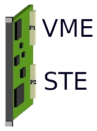
Both ends are 270R, giving a DC pull-up of 135R - On double-height Eurocards, the STEbus connector must be the bottom connector.
This allows it to co-exist with double-height VME boards, which use the top connector:![]()
STEbus
CPU-neutral, professionally designed, industrial strength. Design slave boards that work with any processor.