 Hagen Fritsch
-
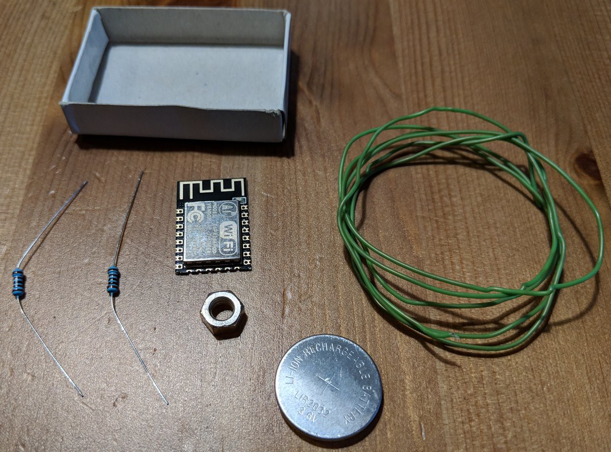
1Gather the components
- A bare ESP8266 module
- 2 1k resistors
- A 3.7V coin cell
- Insulated wire to form the spring
- A nut to give the spring some space
- A match box for casing + some gift wrapping paper for decoration
- A soldering iron + solder
![]()
-
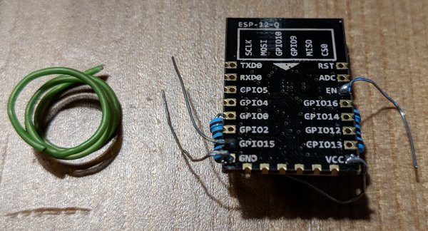
2Connect the resistors
The resistors are permanently needed, so we may connect them already and solder them.
VCC and EN are connected, as are GPIO15 and GND.
The excess wire of VCC will later be used to hold the coin cell.
I also leave the other excess wires present as it allows me to easily connect external power supply for firmware flashing and they automatically hold the device in place within the match box.
![]()
-
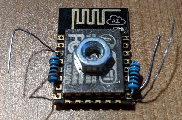
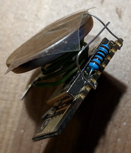
3Attach the spring mechanism
Use the insulated wire to form a spring (as shown above) by wrapping it around a round object, e.g. a pen. The diameter should be slightly larger then the spacing nut.
![]()
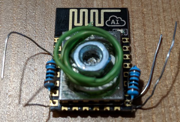
Incidentally, the casing of the ESP is connected to GND, so we can just solder the nut on it.
Now place the spring around it. Make sure it still separates the coin cell from the nut when put on top.
![]()
-
4Add the coin cell
Bend the VCC wire to attach the coin cell (the + side points upwards). I use simple transparent tape to connect it, so I can easily switch the battery if necessary. Make sure to place the coin cell, so that a path from the LED to the top is not obscured.
![]()
-
5Place it in the match box
I simply placed it in the box and used the excess wires to anchor it. This has so far been stable enough.
Gift-wrapping paper was used to decorate the match box. I put a small hole in it, so that the LED light is visible from the outside.
-
6Flash the firmware
Follow the instructions on GitHub – ESP Dash Button to flash the firmware.
Match Box ESP Dash Button
ESP8266 + Coin Cell + Match Box = Dash Button
Discussions
Become a Hackaday.io Member
Create an account to leave a comment. Already have an account? Log In.