Close
0%
0%

Ultimate preamp

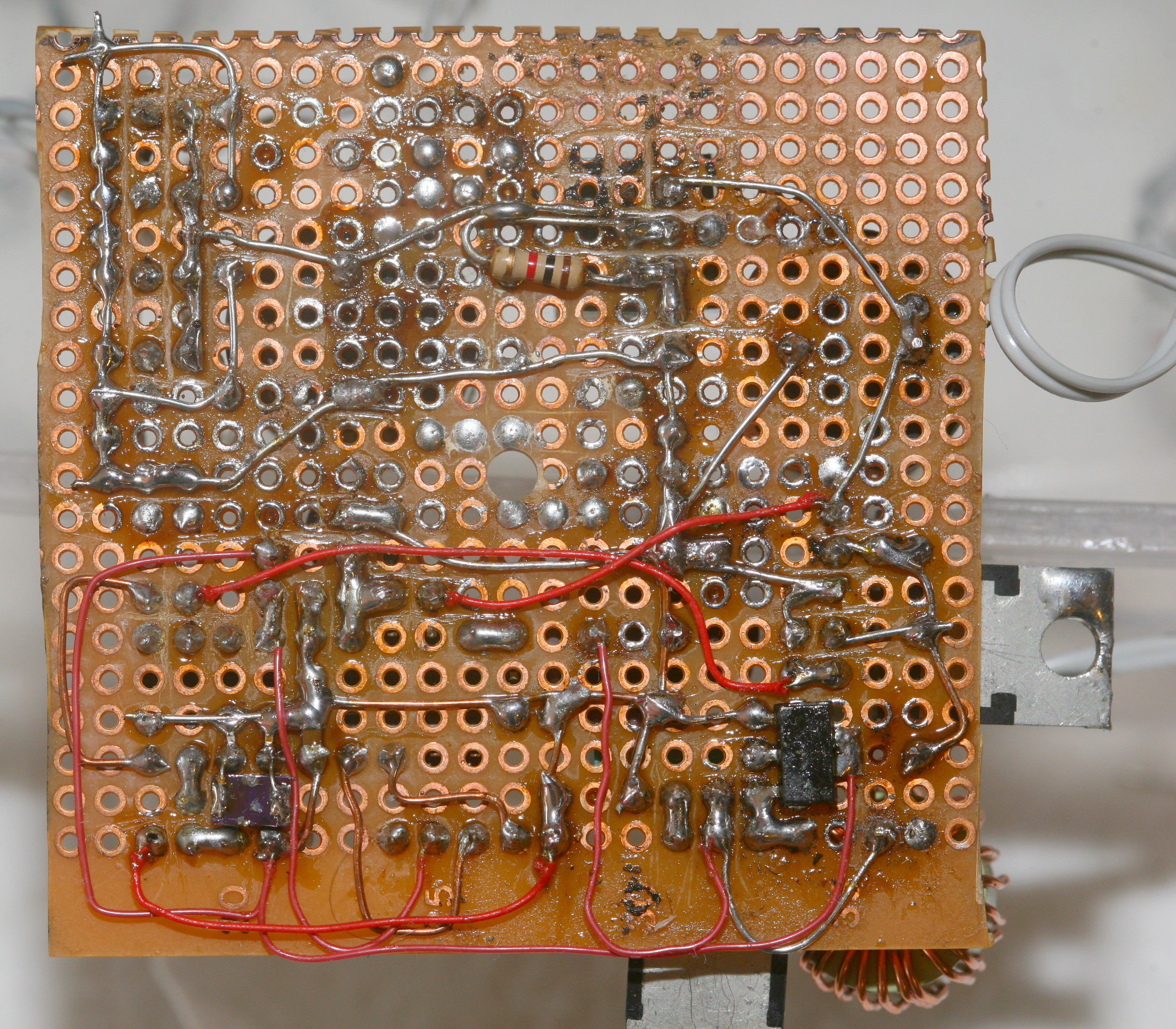
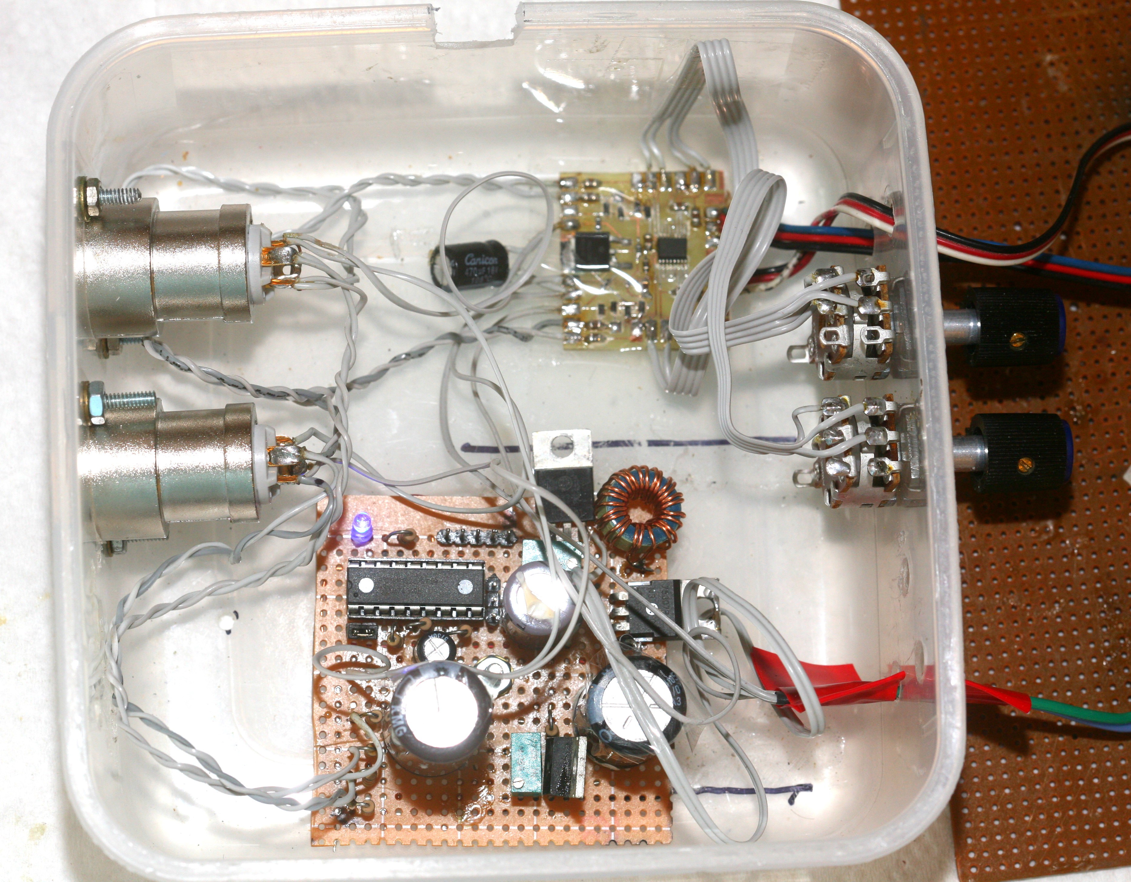
The 1st preamp. Noisy, pointless, but cool.

Similar projects worth following
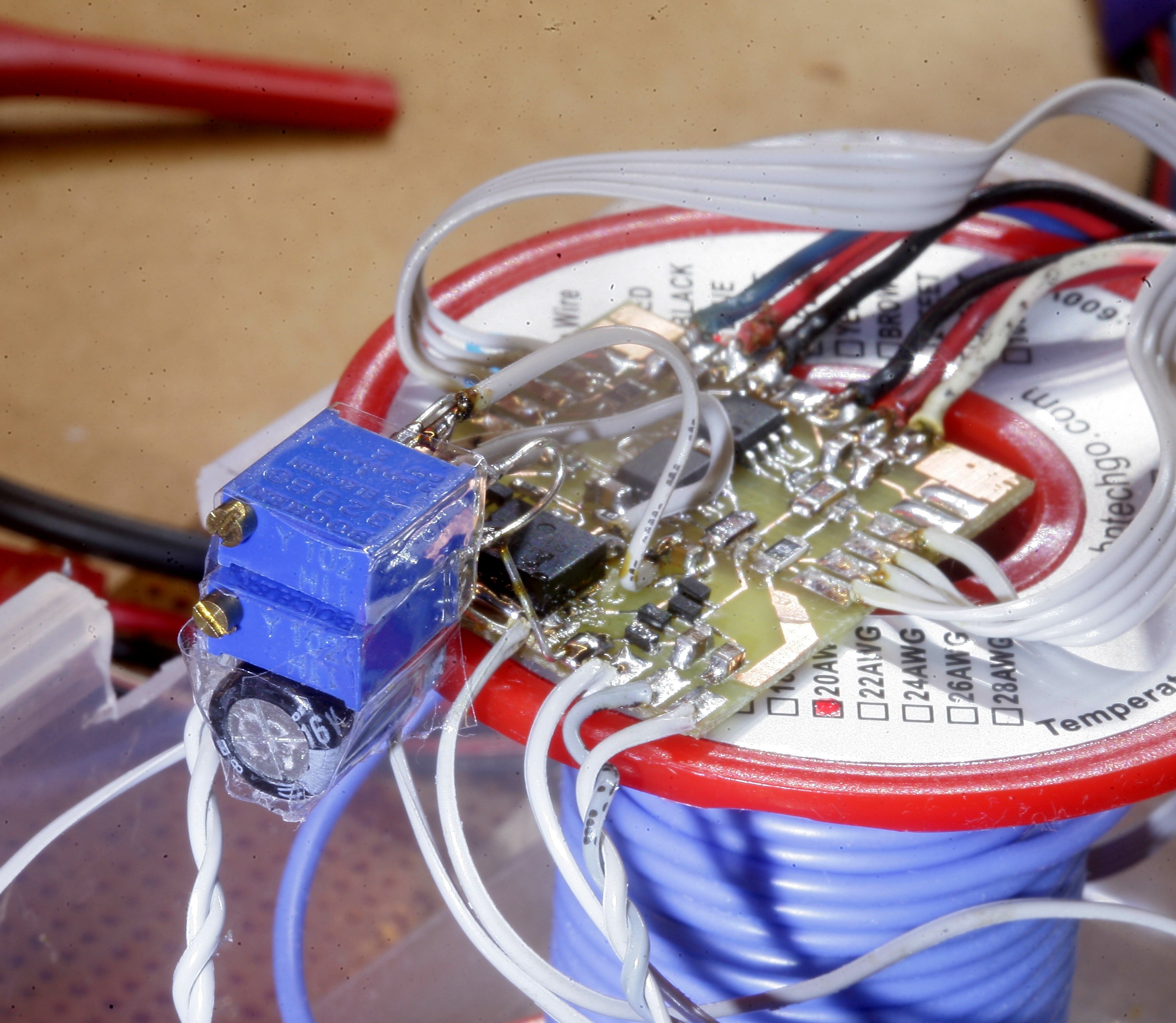
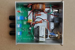
This was the 1st preamp, circa 2011. It was based on the Elliot sound projects low noise preamp http://sound.whsites.net/project13.htm but using 2N2222's. It had a crusty 48V boost converter. It underwent many revisions, but the original belonged in a museum.

In the dinosaur age, we only had analog microphones with big XLR outputs, 48V phantom power, & preamps.  None of this USB nonsense.  The big connectors were cool, anyways.

A big problem was power supply noise.  It couldn't connect to the Zoom without the 2 being powered from separate batteries.  It originally amplified intact differential signals from a single microphone with 2 amplifiers, then the results could be combined in software.  Then it amplified a single end from 2 microphones with 2 amplifiers & threw away the inverse signals.  It was all through hole because nothing could go wrong with audio, but the power line noise was a bitch.

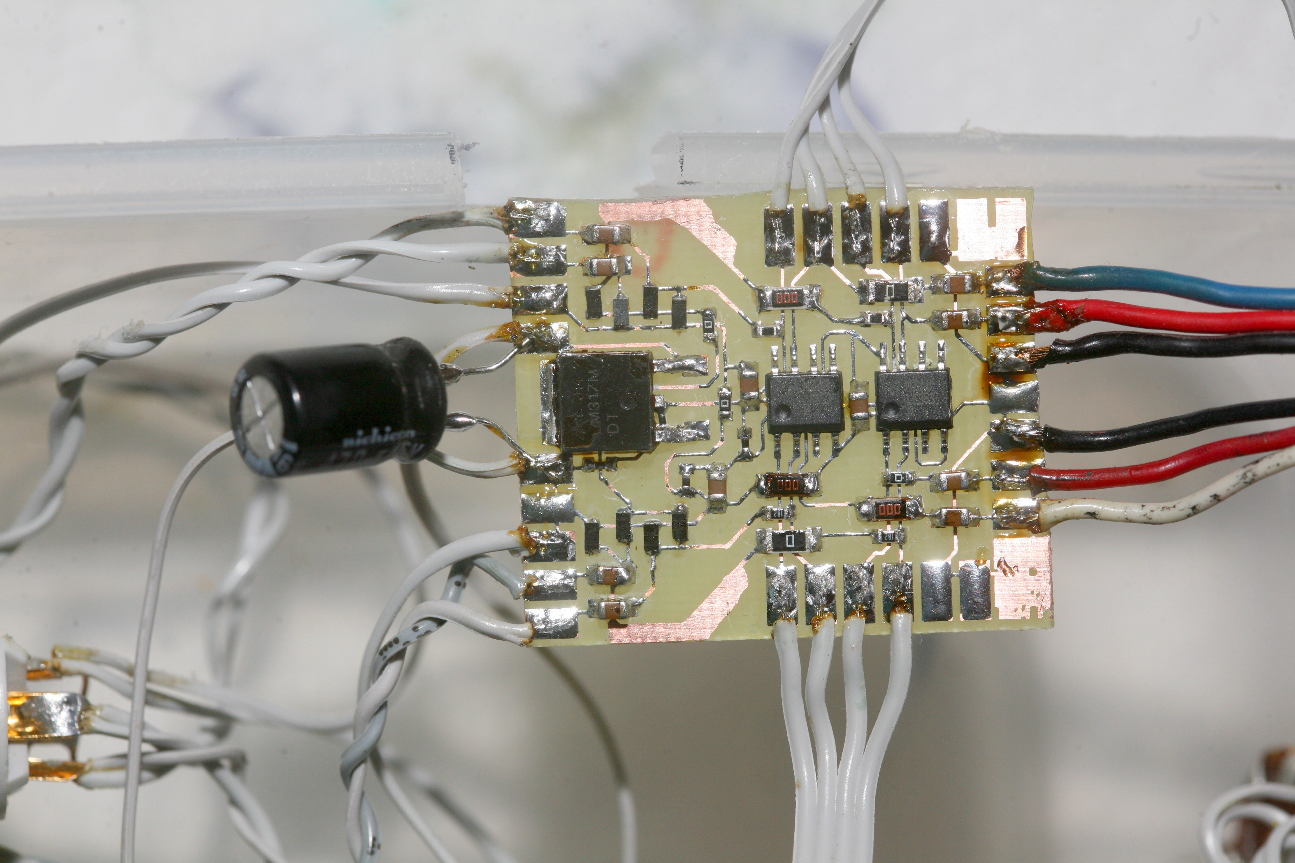
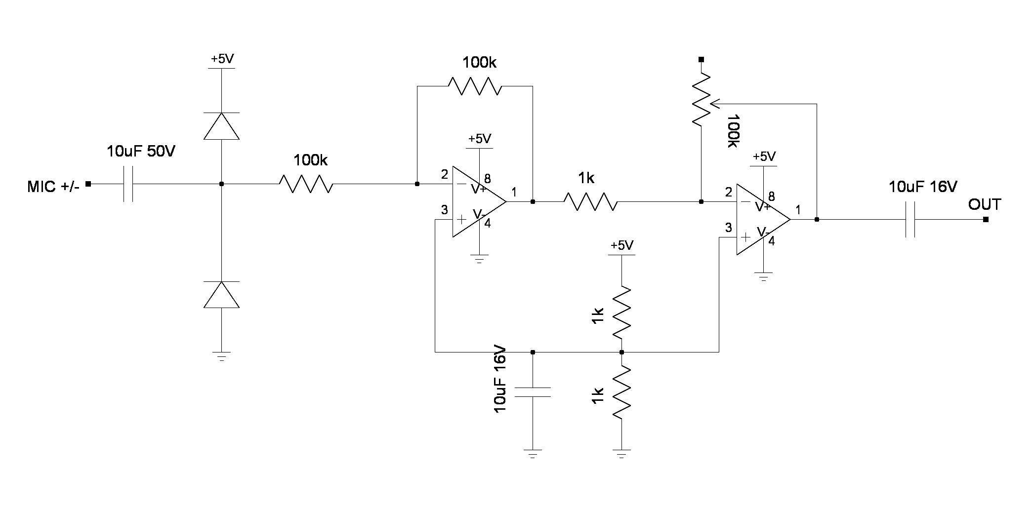
The final version amplified the intact differential signals from the 2 microphones with LF353's.   This eliminated all the power supply noise & it could finally run on the same battery as the Zoom.  It had some diodes to protect it from 48V & was surface mounted.  There's a 5V virtual ground from a regulator.
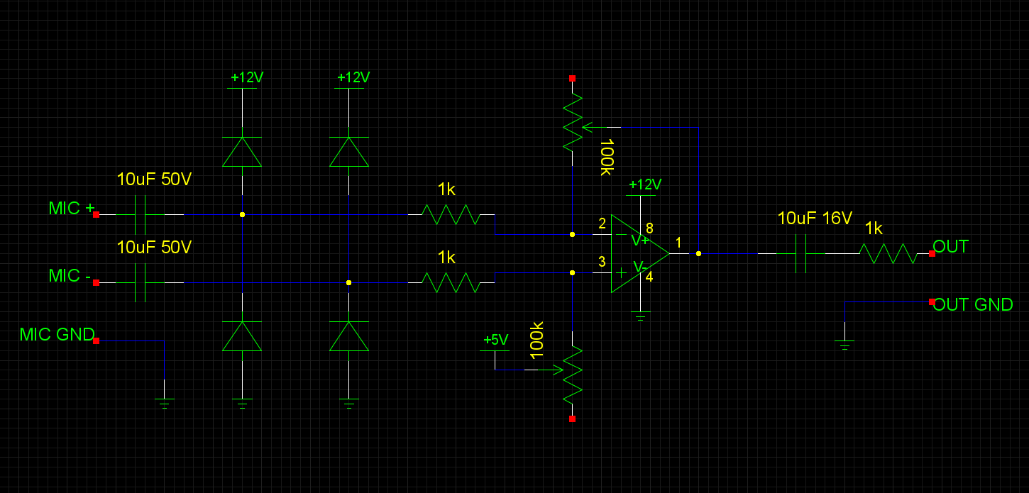
Final design of the preamp stage.

Future developments would be part of the ultimate 4 channel recorder, since the microphones were never used for anything else.  Isn't it easier, more compact, & less utterly pointless just to whack a new pair of USB microphones into a raspberry pi?  Of course it would.  Even the 24 bit 96khz of an external preamp probably can't compare to digitizing right up against the capsule.  Maybe there was a belief a better analog microphone would come along or it would be like vinyl.
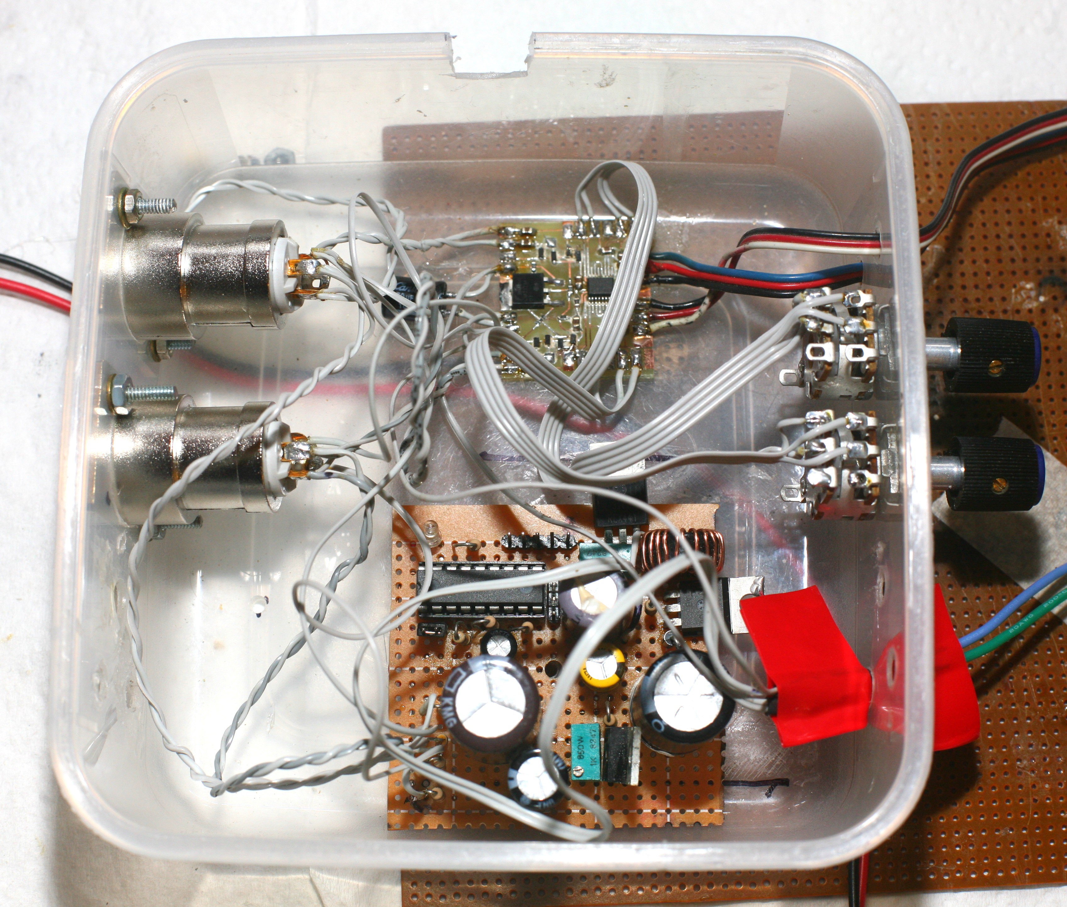
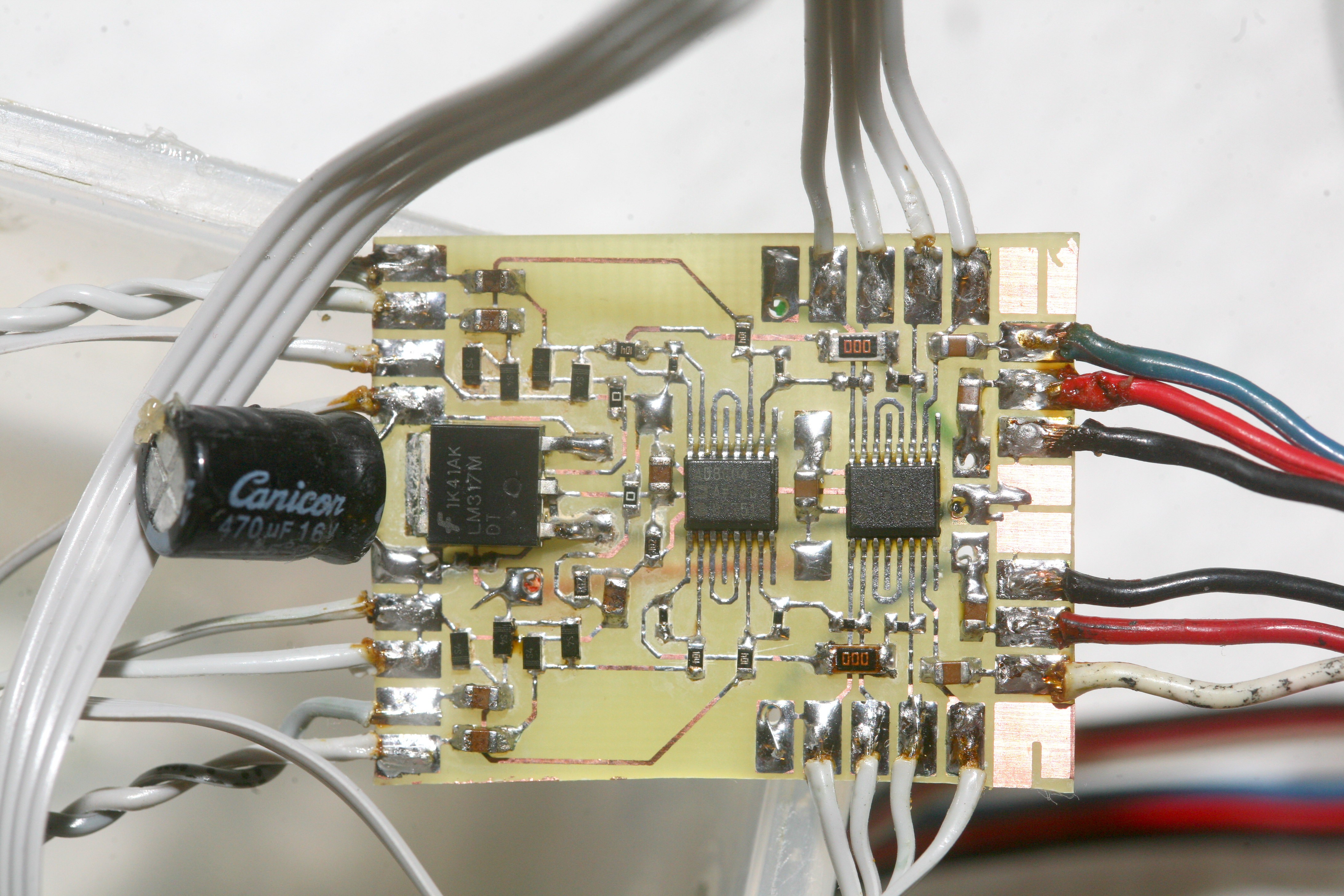
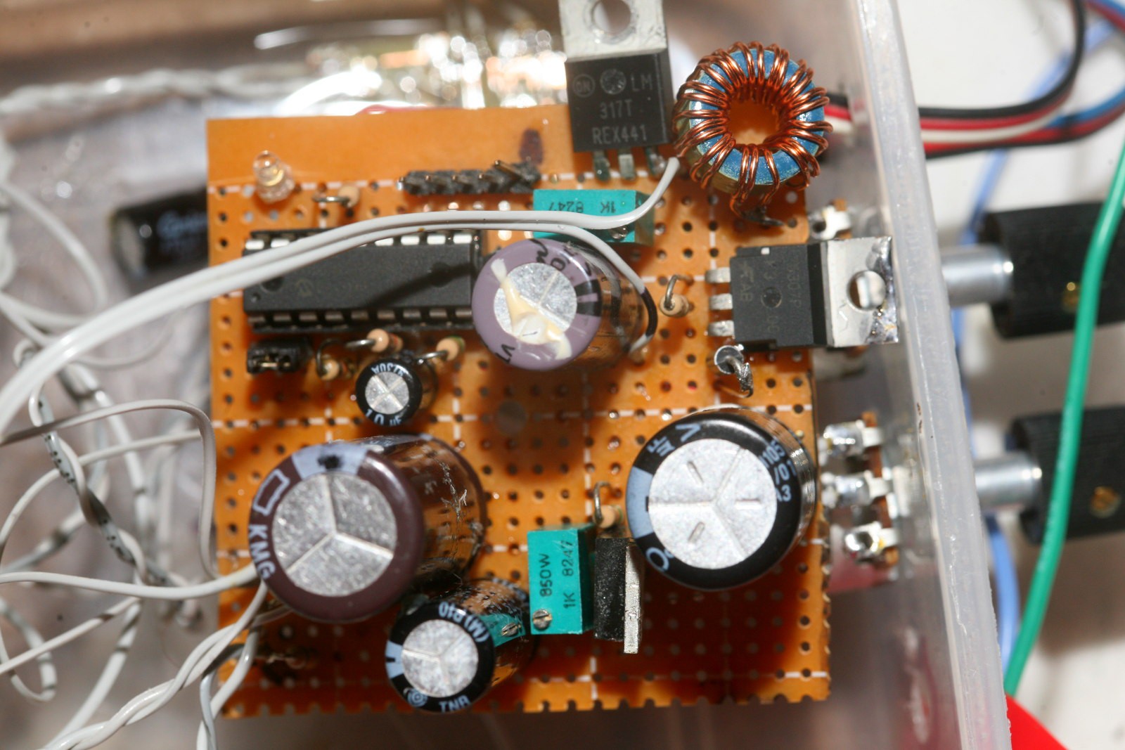
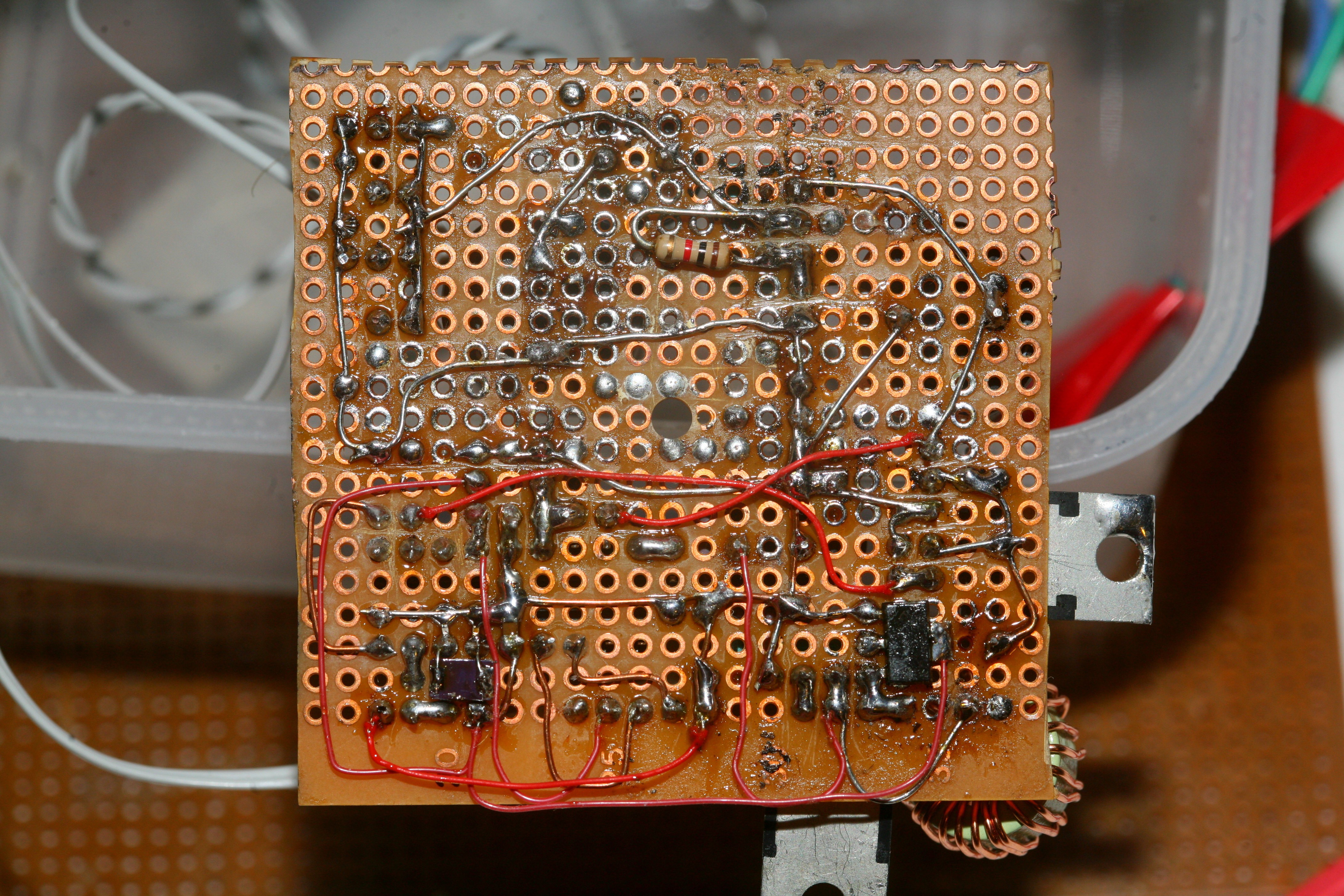
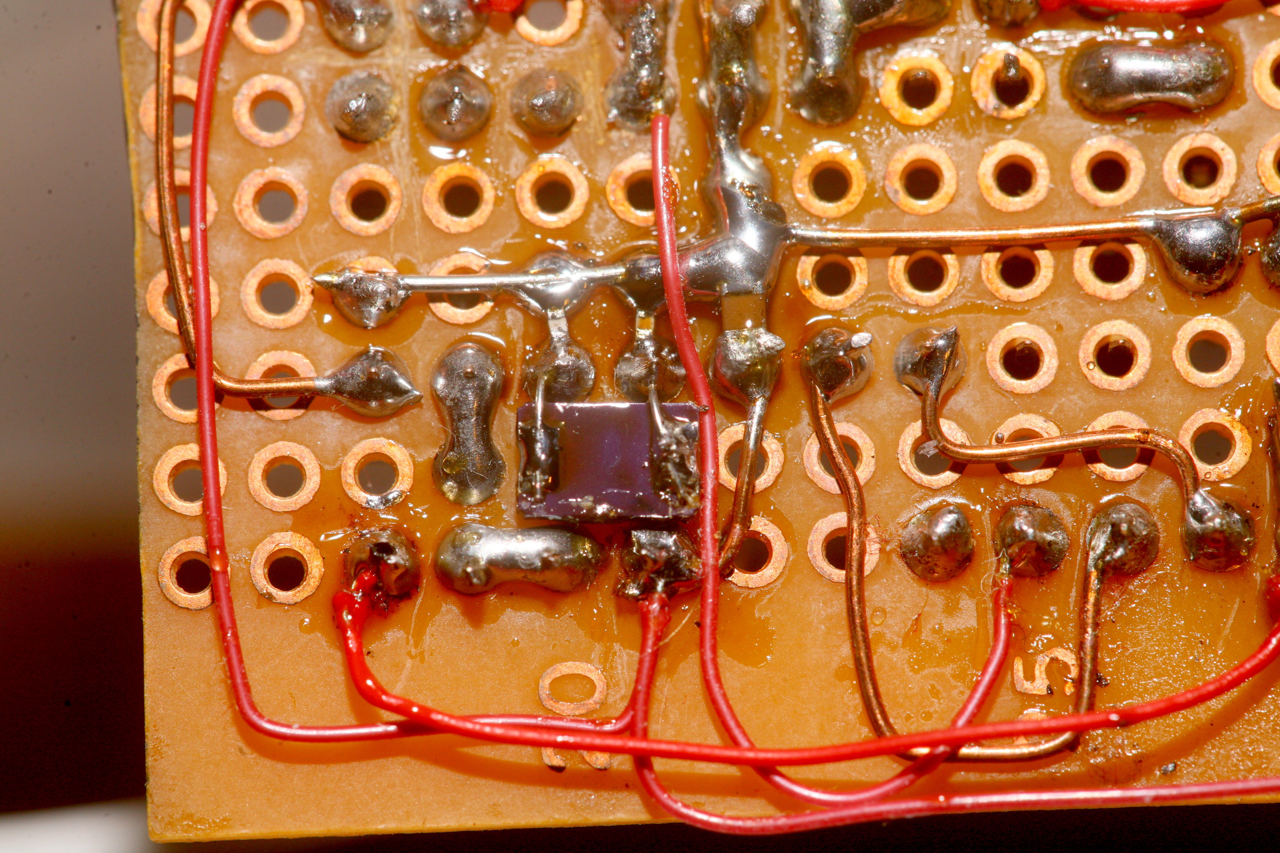
A revised design in 2018 was much more efficient.
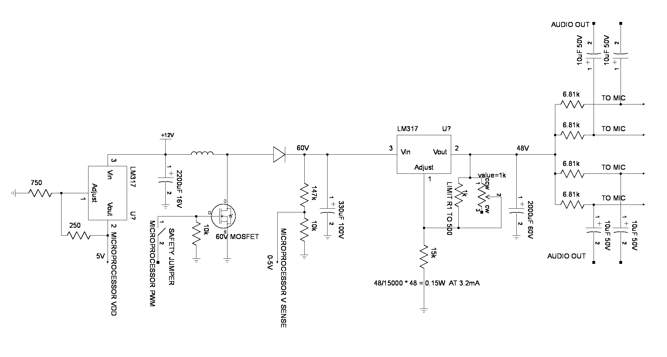
The new boost converter used a linear regulator to drop an unstable 50-60V to a stable 48V.
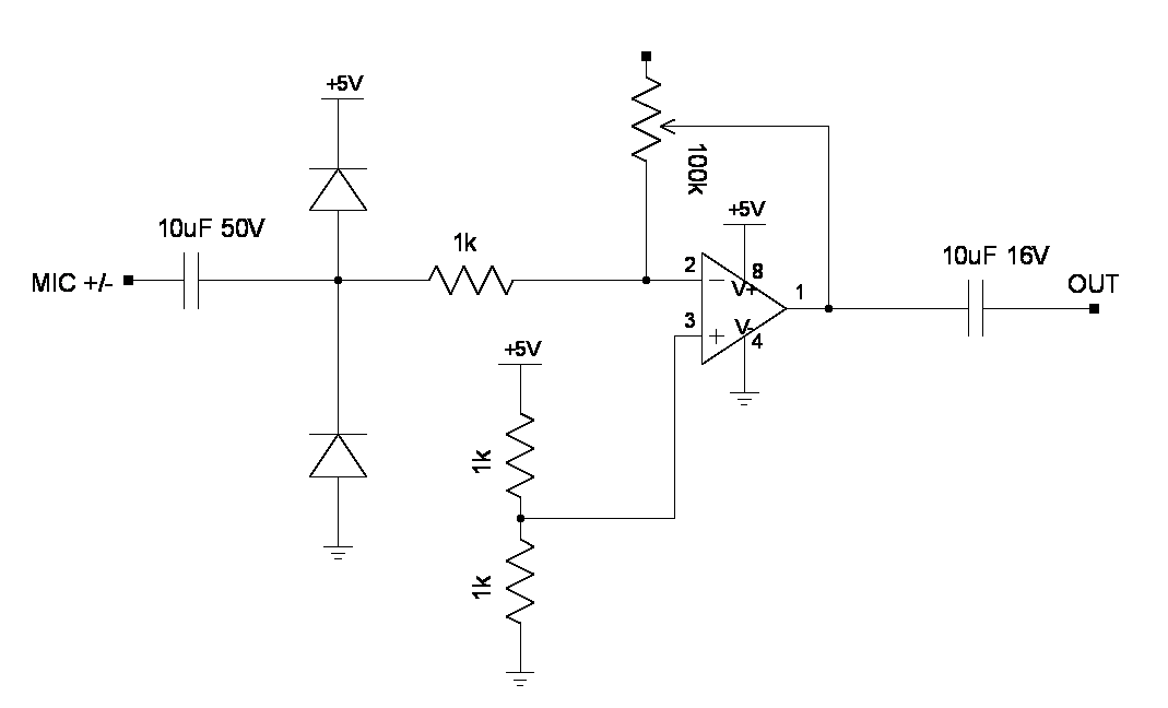
The new amplifier section was just 4 inverting amplifiers.  The input resistance is too low, but it's good enough.  Minimizing noise & harmonic distortion on such a circuit can be an obsession.

https://cdn.hackaday.io/files/292031249421152/mane.c

New but extremely simple booster firmware handled the newer voltage.

mane.c

Booster firmware which compiles in MPLAB.

text/x-csrc - 8.12 kB - 01/22/2018 at 06:16

Download

test.wav

Just the normalized noise. Maximum gain with phantom power but no microphone connected.

Waveform Audio File Format (WAV) - 966.47 kB - 01/22/2018 at 02:56

Download

  • Voltage ripple in phantom power

    lion mclionhead10/26/2019 at 22:10 0 comments

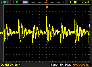
    The ripple coming out of the phantom power is 100mV at 100khz but it's canceled out by the differential signal.  The loss would be from the head room.  It's not affected by the gain.  Since it's not affected by the gain, the lion kingdom would almost say it's a probing artifact.

    A bag full of commercial boost converters capable of creating phantom power & powering lighting was on the wishlist.  Behold the mighty XL6019 reference design.

    https://www.amazon.com/s?k=xl6019&i=electronics&ref=nb_sb_noss_1

    There's a review showing it being limited to 40V, but it can probably be hacked to 55.

    The datasheet claims 60V as the absolute maximum.

    http://www.xlsemi.com/datasheet/XL6019%20datasheet-English.pdf

    No-one reviews the ripple at high voltages, but they're probably no better than the home made boost converter since all switching converters are noisy.  The best option might be just using a faster microcontroller for the home made boost converter.   No-one has torn down a Zoom recorder enough to reveal any secrets, but the lion kingdom suspects they use noisy switching converters.

    The only gear making truly flat phantom power would manes powered.  That would use a toroid transformer & linear regulator.  No-one tears down pro audio gear.


    Lions have run the pre-amp on a Rudung switching converter with no problems.  The differential signal cancels out effectively, despite being in software.  It would be worthless for a non differential electret microphone, however.


    Then the lion kingdom noticed clipping in a voiceover that was well below the full range of the waveform.  

    Could this have been the loss of headroom caused by the ripple?    The ripple should have made clipping look more like noise than a flat line.

    The preamp famously used a fixed 5V regulator which was known to limit the peaks slightly below the full range of the 5V ADC's.  It was only a 2dB loss on the meters.  That didn't seam like a lot until the lion kingdom saw how many pixels it was from the waveform edge.  A variable regulator would be required.

    2 tongue angle adjustments were required for the voltage regulator & for the virtual ground.  It needed a 6V & a 3V to completely reach the rails.  The LF353 op-amps had a 0.5V dropout voltage on the high & low ends.

  • Defeating ripple

    lion mclionhead08/30/2018 at 00:39 0 comments


    The 1st transistor circuit lions ever used was the emitter follower as the high side of an h-bridge. Never knew the applications or that it was formally a design.

    It turns out the emitter follower is a way of eliminating voltage ripple, though very obscure.  Years of goog searches for defeating ripple yielded only RC circuits. Even coworkers with a lot more degrees than lions used only RC networks. Lions used linear regulators right until this video, with very frustrating results. The microphone preamp just accepted very high output ripple in exchange for less headroom. The audio recorders just sacrificed huge amounts of space for giant capacitors.

    A lot of circuits can now get a lot smaller. Suspect ADCs which specify 5V & suddenly get very noisy below 5V are all using emitter followers to defeat ripple.

  • AD8604 vs LF353

    lion mclionhead02/04/2018 at 22:50 0 comments

    Compiled the single stage recording of the AD8604 with the LF353.  The AD8604 still has the original cell phone interference.  Suspect the sound of the freeway was not different, but we're still hearing the effect of less noise on a normalized signal.  The freeway is 1 mile away & an ever present sound.  The freeway sound is manely affected by fog.  Fog makes it go away.  Clear nights make it very loud.  Never noticed its timbre changing on 2 different clear nights.  

  • Frequency response vs gain

    lion mclionhead02/04/2018 at 00:19 0 comments

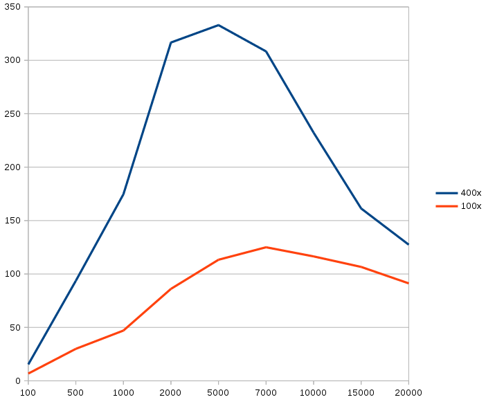
    It was a rough frequency sweep, by manually tweeking the signal generator.  The measurement was only between the microphone output & preamp output.  The instruments were tested to be flat.  As expected, the higher the gain, the lower the cutoff frequency.  The higher R ratio just makes it less flat.  The 4Mhz GBW of the LF353 did what GBW's do.  

     Surprising to see so much loss in the low frequencies.  It was good to see the peak gain achieving the full R ratio.

    A younger lion would have had a digital pot clearly showing the point where the gain crossed 100x, with an option to go to 400x.  An old lion just limits it to 100x.

    In terms of the microphone's JFET amplifier, its voltage gain was consistently 2 across the frequency range.  

    This page

    http://sound.whsites.net/project66.htm

    had some nuggets about noise.  Manely, fixed regulators are noisier than adjustable regulators.  A resistor alone generates 260nV of noise.  There are formulas for converting the op-amp's stated noise density to a SNR.

  • Dual vs single stage

    lion mclionhead02/03/2018 at 07:23 0 comments

    Decided to revert back to a single stage amplifier, but also go back to the LF353.  Noise density for 3 popular op-amps:

    OPA227: 3nV

    AD8604: 33nV

    LF353: 16nV

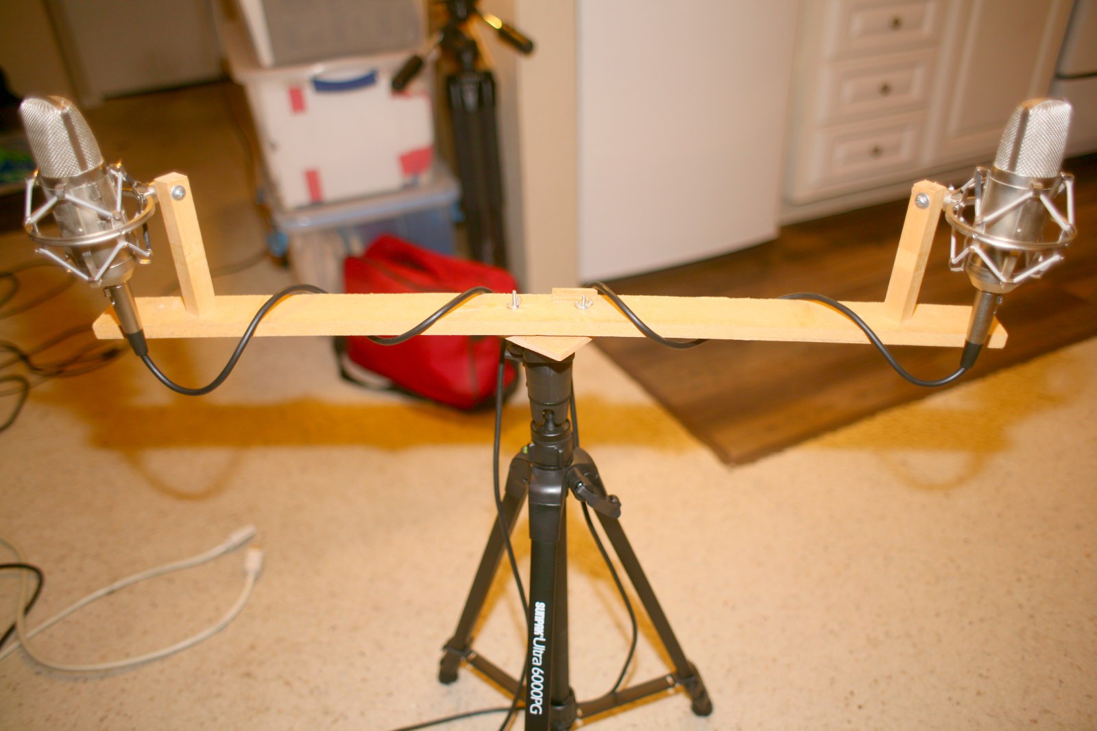
    Also made a better binaural stand.  Despite the cardiod pattern, testing showed spacing them 2ft apart like omni's yielded better stereo separation.

    The result was of course a mixed bag.  Both recordings were normalized.  To make it easier, they were made indoors.  Both sounded like noise.  Fortunately, being experienced  flat broke renters, lions know the noise in the 2nd recording is water outside the apartment.  Despite much higher gain, the 1st recording couldn't resolve the sound of water outside & it's very obvious.

    It's an extreme difference, from just removing an input op-amp stage.  It makes you wonder how far a preamp could go with better op-amps, single transistor designs, better power supplies, metal film resistors, if time & money were unlimited.  It also shows negative results from Chinese microphones may be from people using crummier amplifiers.

    It was a very educational experience, showing as long as the signal is above the ADC noise & the recording medium's noise, the op-amp noise is a significant factor & higher gain is not as important as signal to noise ratio.  In the days of tape & soundblaster 16's, the recording medium was a bigger source of noise than the input stages, so the VU meters needed to be as high as possible.  Those days are over.  Nowadays, you're actually better off with the VU meters down in the weeds.

  • Dual vs single stage

    lion mclionhead01/30/2018 at 09:13 0 comments

    The dual stage comes 1st, then the single stage comes at 30 seconds.  Both were normalized & highpass filtered to eliminate construction noise.  They were on different nights with possibly different sound levels.  It was found that moving the phone & battery far away from the preamp reduced RF noise in the single stage.  This noise shouldn't be affected by the gain, though the wifi noise in the ADC is.

    The lion kingdom's subjective opinion is the single stage had a lower noise floor, despite being closer to the ADC noise floor.  The datasheet for the AD8604 backs this up by claiming a 33nV noise density while the OPA227 claims a 3nV noise density.  Presumably, multiple stages of AD8604 have a significant noise increase, but the AD8604 has a real high GBWP & costs a lot.  

    Otherwise, there may be a mistake in the gain calculations, since the gain with no microphone may resemble an instrumentation amplifier while the gain with a microphone may resemble dual isolated amplifiers.  Either way, the gain is more with 2 stages.

  • Dual stage

    lion mclionhead01/29/2018 at 07:33 0 comments

    The long awaited upgrade to dual stages happened.  Self noise went from -79 to -53db so pow(2, (26 / 6)) = 18x rise in noise floor.   What motivated it were wifi pops every 2 minutes in the ADC.  They only happen in the AUX channel.  Maybe the analog side should all run on a separate battery, as was done 7 years ago.  

    The 1st stage has a 1.9x gain because of the 6.8k's in the phantom power, so it achieves a total of 194x.  The single stage had 14x.  The theoretical increase should be 6 * sqrt(194/14) = 22db, so it either added another 4db of noise or the single stage was less efficient.  

  • Line noise

    lion mclionhead01/27/2018 at 23:12 0 comments

    60Hz line noise was another problem in the weeds of the noise floor.

    Putting a ground line around the 6.8k resistors gave a questionable improvement. The biggest improvement came from

    moving the power & ground lines away from the pots & the twisted pairs.  This kind of noise reduction isn't going to be consistent, as it's transported.  Digital pots & flood filled grounds are necessary .

    Transient pops are still a problem in the aux channel.  Disabling phantom power & running the preamp on batteries didn't fix it.  Still debating upgrading the preamp to 100x.

  • Booster tweeks

    lion mclionhead01/27/2018 at 05:03 0 comments

    After being defeated by the op-amp, the lion kingdom was determined to try another idea.  1st, maximized the booster frequency by powering it on 9V instead of 7V.  The battery would have to stay above 11V to get good results, but it got to 60khz - 150khz.  The booster frequency changes still made a lot of pops.  


    So in another legendary bodge, the clock was upgraded to 40Mhz & the inductor windings were doubled.  It still showed 5uH, but less resistance.  The feedback increments should be smaller so the pops should be quieter.  There was a bug causing the duty cycle to be 1/8 of the period.  Got it up to 1/4 before the PIC started resetting.

    With these upgrades, the no load frequency was now 666khz.  The dual microphone frequency was 344khz.  So no more worries about the nyquist frequency & it was holding between 54 & 56V.  The ADC was running much faster, so the feedback could be a lot faster.

    At this point, I remembered that in PIC PWM, the duty cycle has 4x more resolution than the period, so the pops were because of the large steps in varying period instead of duty cycle.  Fixed the frequency at 250khz.  The fluke now showed 54.2-55.3V for the ripple with a full load.  The duty cycle was 22%.

    For the empty load, it was 54.6 - 55.1V & a duty cycle of 14%.

    Unfortunately, this made the pops go full scale.  By maxing out the frequency, the finer feedback steps were still bigger relative to the total range than they were at the lower frequency.  The trick was to use the lowest frequency possible with the finest feedback steps.  

    Set the frequency to 66khz.  The no load duty cycle was 7% & the full load duty cycle was 11%.  The pops were a bit more silent than yesterday, but now there was the issue of a much higher ADC rate & much finer duty cycle allowing much tighter voltage control.  Maybe it was tight enough for the 7 year old min & max voltage bouncer to work.  

    It did indeed work, but the minimum voltage had to be above 54V or the noise increased dramatically.  Also lowered the inductor input voltage so its regulator would have a 4V drop, but this made no difference.

    The other thing which increases the granularity of the feedback is using the highest possible duty cycle, but this costs efficiency.  With 8V going into the inductor, the duty cycle got to 13% for the full load.  To get the best results, this home made booster needs a while to initialize.  Once settled, the booster can probably go an entire session without any feedback.

  • On being clueless with op-amps

    lion mclionhead01/25/2018 at 09:43 0 comments

    For today's game, reduced the home made inductor from 10uH to 5uH & added an LM317, so it now boosted 7V to 55V.  Changed the feedback to frequency instead of duty cycle.  With no load, it hit 100khz.  With 2 microphones, it hit 40khz, well below the nyquist but hopefully cancelled out by the differential pair.  Suspect a flyback transformer is in the future.

    This dropped the common mode noise by another 10db, but the differential noise was still there at -78db.  Depending on where in the room it was, it had more 60hz noise or more wifi.

    So the next step was measuring the differential noise while playing with the preamp inputs.  With them disconnected from phantom power, the differential noise completely went away or -89db.  With them shorted, the differential noise hit a whopping -60db.  With an 8k pot between them, it was -72db.  With a 100k pot between them, it was -86.

    It became clear that when connected to phantom power, the preamp was like an instrumentation amplifier with Rgain being the 2 * 6.8k + 2 * 1k & R1 being 100k.  The 2nd stage is the ADC with gain 1.  The input was going into the negative inputs instead of the positive inputs.

    Though each op-amp has a 100:1 gain, the maximum difference the preamp can generate is 1 + 200k/(2*6.8k + 2k) = 12x but much noisier than each op-amp alone.

    The voltage follower from a few blog posts ago was only a single ended test, so tried it again in differential mode.

    The gain was so much higher, it had to be viewed in 1/16384 per y.  This revealed the noise was a function of the op-amp simply not doing anything when no current flows through its input.  If the input is an open circuit, the gain is 0 & there's no noise.  If the input has current flowing through it, the gain is nonzero & there's noise.  There's nothing the phantom power can do to reduce the noise.

    While the matcher achieves 100x gain, there's little point in leaving it in because even 12x gain gets the noise floor well above the ADC noise.  The microphone is on top of that.

    Lions are fans of using the fewest components possible.  It's all a game to do everything in a single layer & a single op-amp.  If every circuit had to be horrendously complicated, they would give up & focus on web apps.

View all 16 project logs

Enjoy this project?

Share

Discussions

Similar Projects

Does this project spark your interest?

Become a member to follow this project and never miss any updates