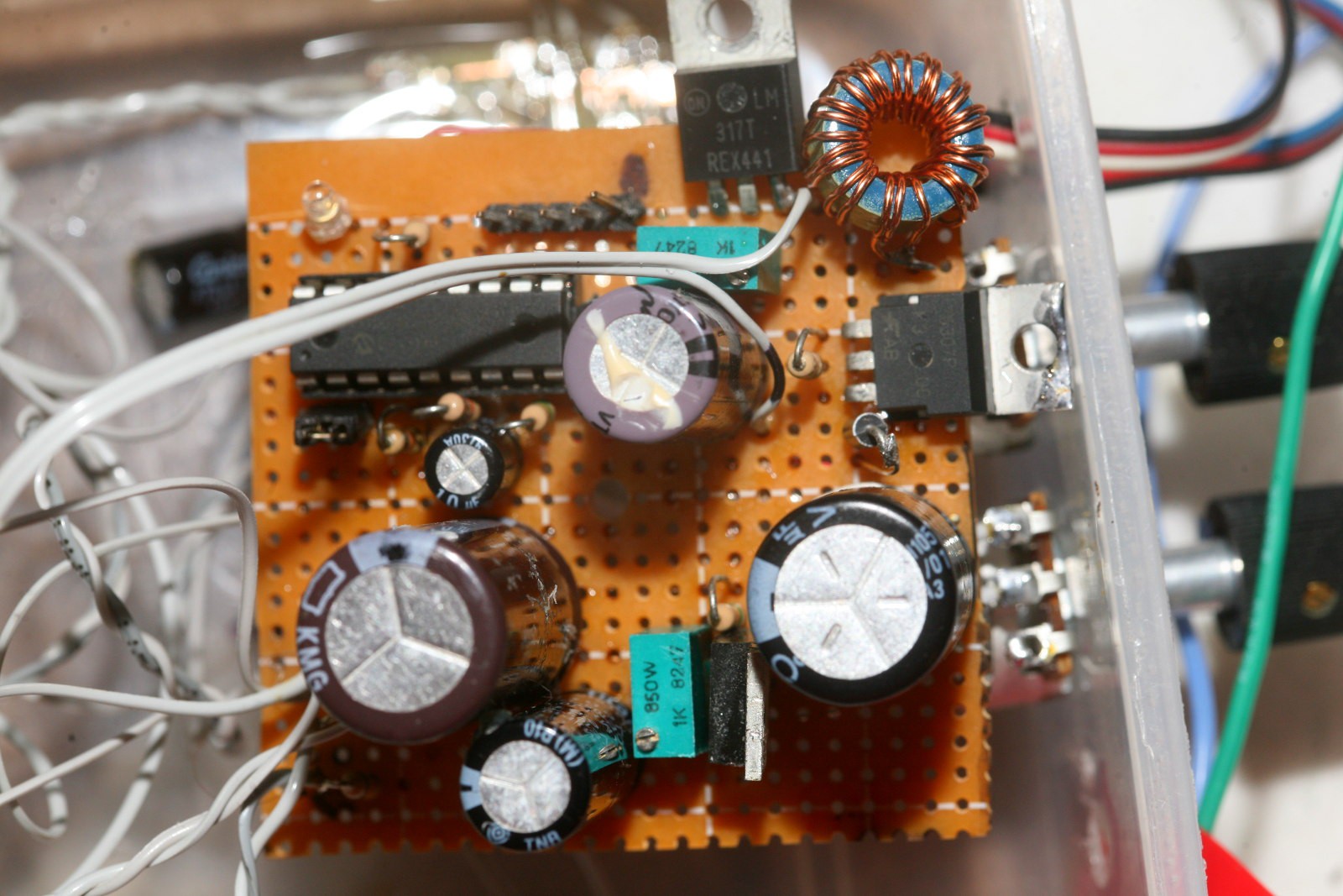
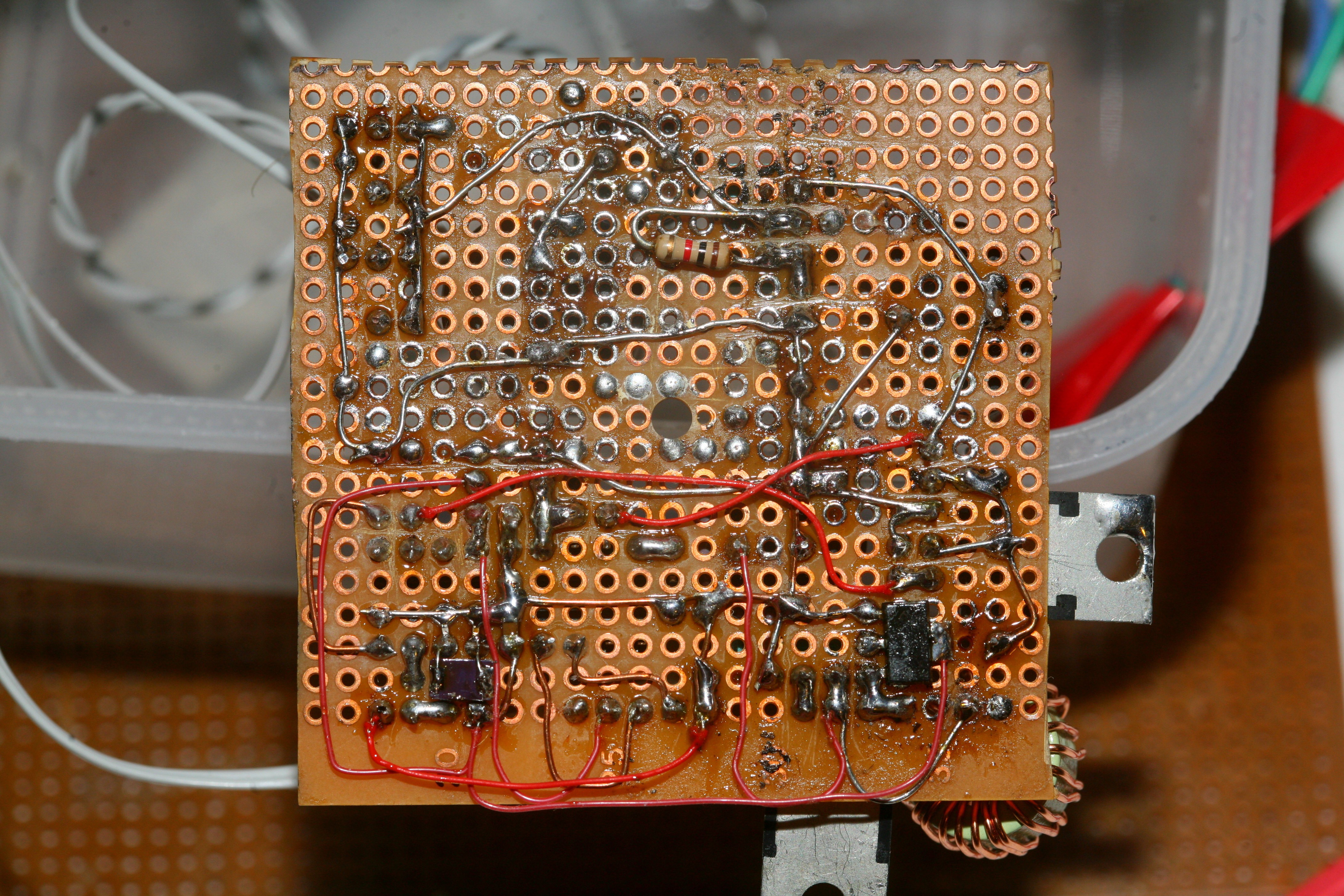
After being defeated by the op-amp, the lion kingdom was determined to try another idea. 1st, maximized the booster frequency by powering it on 9V instead of 7V. The battery would have to stay above 11V to get good results, but it got to 60khz - 150khz. The booster frequency changes still made a lot of pops.


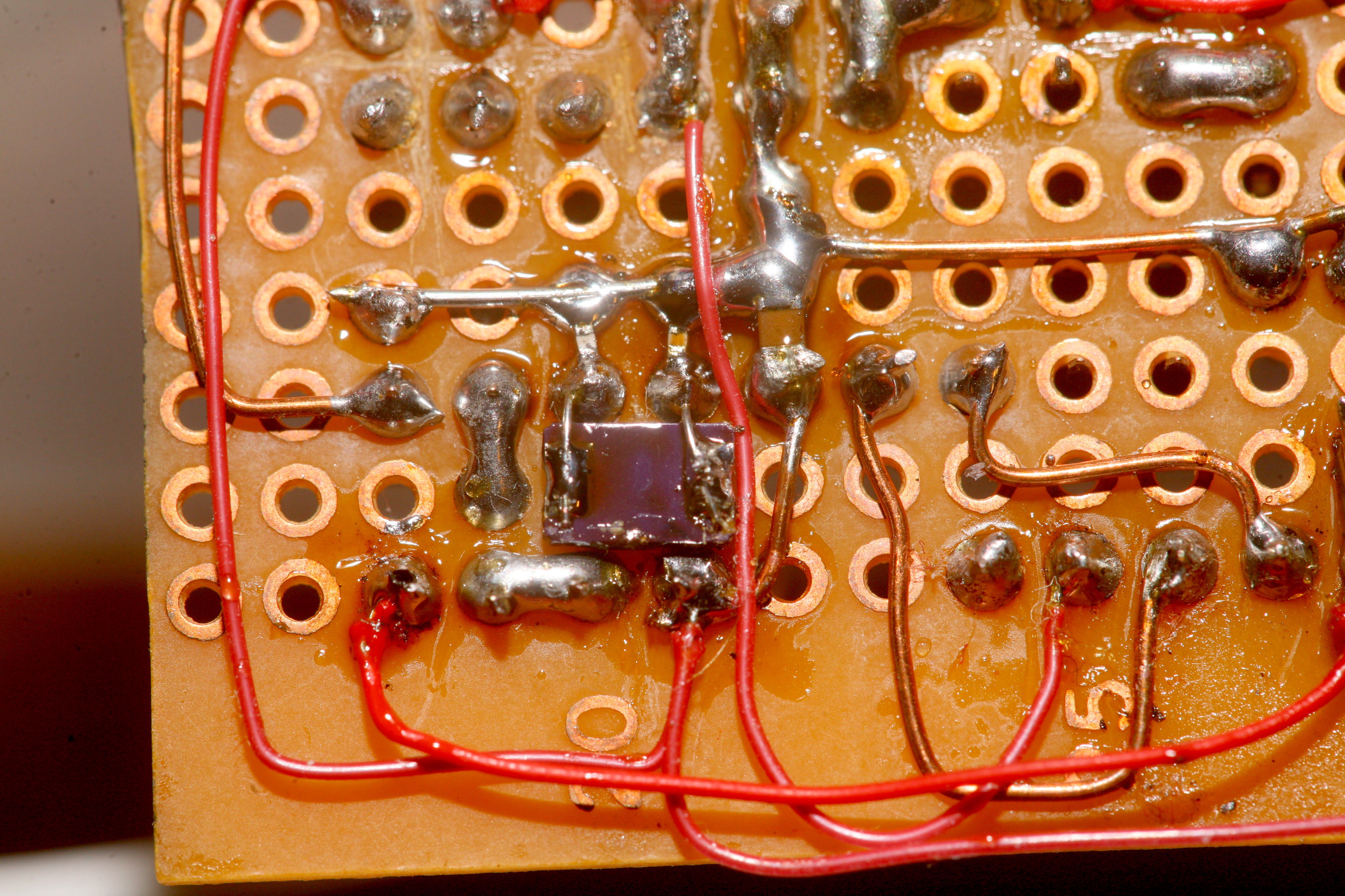
So in another legendary bodge, the clock was upgraded to 40Mhz & the inductor windings were doubled. It still showed 5uH, but less resistance. The feedback increments should be smaller so the pops should be quieter. There was a bug causing the duty cycle to be 1/8 of the period. Got it up to 1/4 before the PIC started resetting.
With these upgrades, the no load frequency was now 666khz. The dual microphone frequency was 344khz. So no more worries about the nyquist frequency & it was holding between 54 & 56V. The ADC was running much faster, so the feedback could be a lot faster.
At this point, I remembered that in PIC PWM, the duty cycle has 4x more resolution than the period, so the pops were because of the large steps in varying period instead of duty cycle. Fixed the frequency at 250khz. The fluke now showed 54.2-55.3V for the ripple with a full load. The duty cycle was 22%.
For the empty load, it was 54.6 - 55.1V & a duty cycle of 14%.
Unfortunately, this made the pops go full scale. By maxing out the frequency, the finer feedback steps were still bigger relative to the total range than they were at the lower frequency. The trick was to use the lowest frequency possible with the finest feedback steps.
Set the frequency to 66khz. The no load duty cycle was 7% & the full load duty cycle was 11%. The pops were a bit more silent than yesterday, but now there was the issue of a much higher ADC rate & much finer duty cycle allowing much tighter voltage control. Maybe it was tight enough for the 7 year old min & max voltage bouncer to work.
It did indeed work, but the minimum voltage had to be above 54V or the noise increased dramatically. Also lowered the inductor input voltage so its regulator would have a 4V drop, but this made no difference.
The other thing which increases the granularity of the feedback is using the highest possible duty cycle, but this costs efficiency. With 8V going into the inductor, the duty cycle got to 13% for the full load. To get the best results, this home made booster needs a while to initialize. Once settled, the booster can probably go an entire session without any feedback.
 lion mclionhead
Discussions
Become a Hackaday.io Member
Create an account to leave a comment. Already have an account? Log In.