-
Chasing the noise
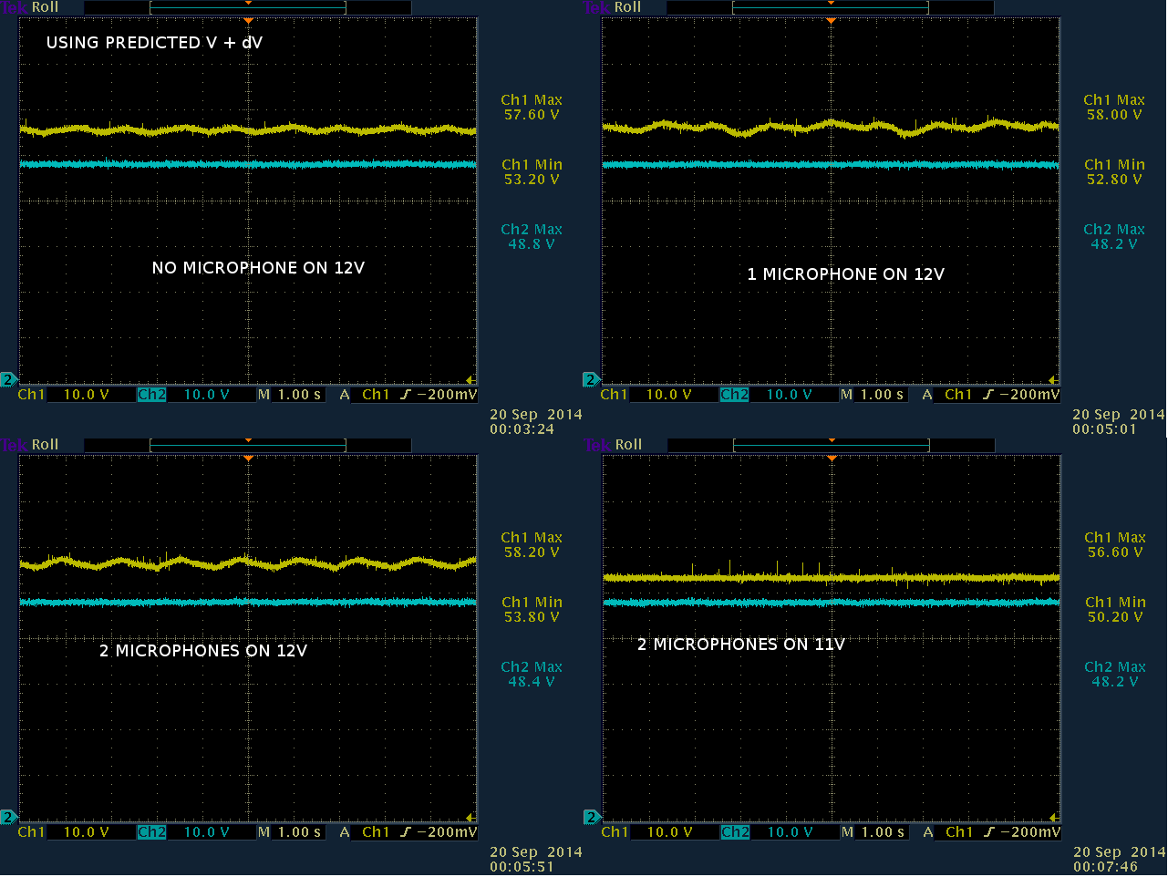
01/24/2018 at 08:33 • 0 commentsThrough removing components, discovered unplugging 12V from the booster eliminated the noise. The problem was noise in the 12V supply. The filter capacitors are high pass filters between 12V & ground, so connecting the amplifier to ground would cause more noise than letting it float.
![]()
A 5ohm resistor reduced the common mode noise, but suffered more differential noise of the 60 Hz variety, for some reason. All configurations were quieter on battery power than the zillion dollar Agilent. It definitely needs a linear regulator to drop a higher voltage to 12V like the ADC does. A 15V battery would do the job, but cost more than a commercial preamp. Making the booster run on 6V would be ideal.
Suspect for the Zoom H6 to have all the features it has, in such a small space, it must have extremely poor audio quality.
-
Matching circuit test
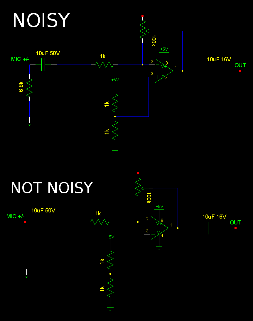
01/23/2018 at 07:34 • 0 commentsWhile tracking down a wrong resistor value, noted that attaching a 68k resistor to the phantom power output instead of a 6.8k made the noise drop.
![]()
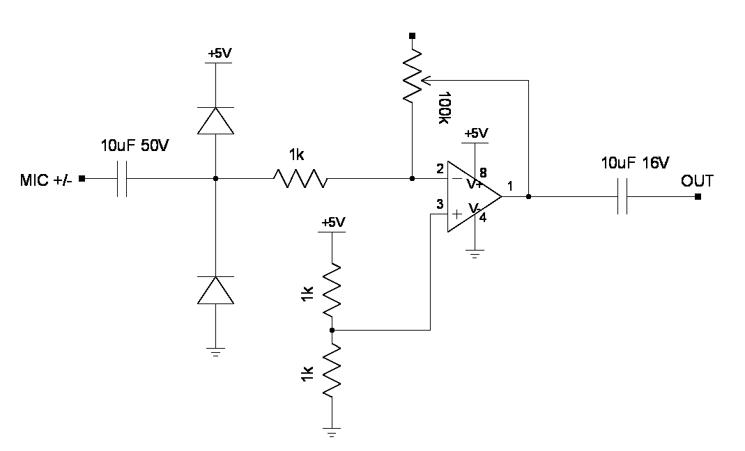
Based on the master plan, there's only 1k of input resistance in the amplifier, but 6.8k of output resistance from the phantom power. So theoretically, all the noise inside the phantom power is amplified by 100/7.8 with no microphone connected.
![]()
![]()
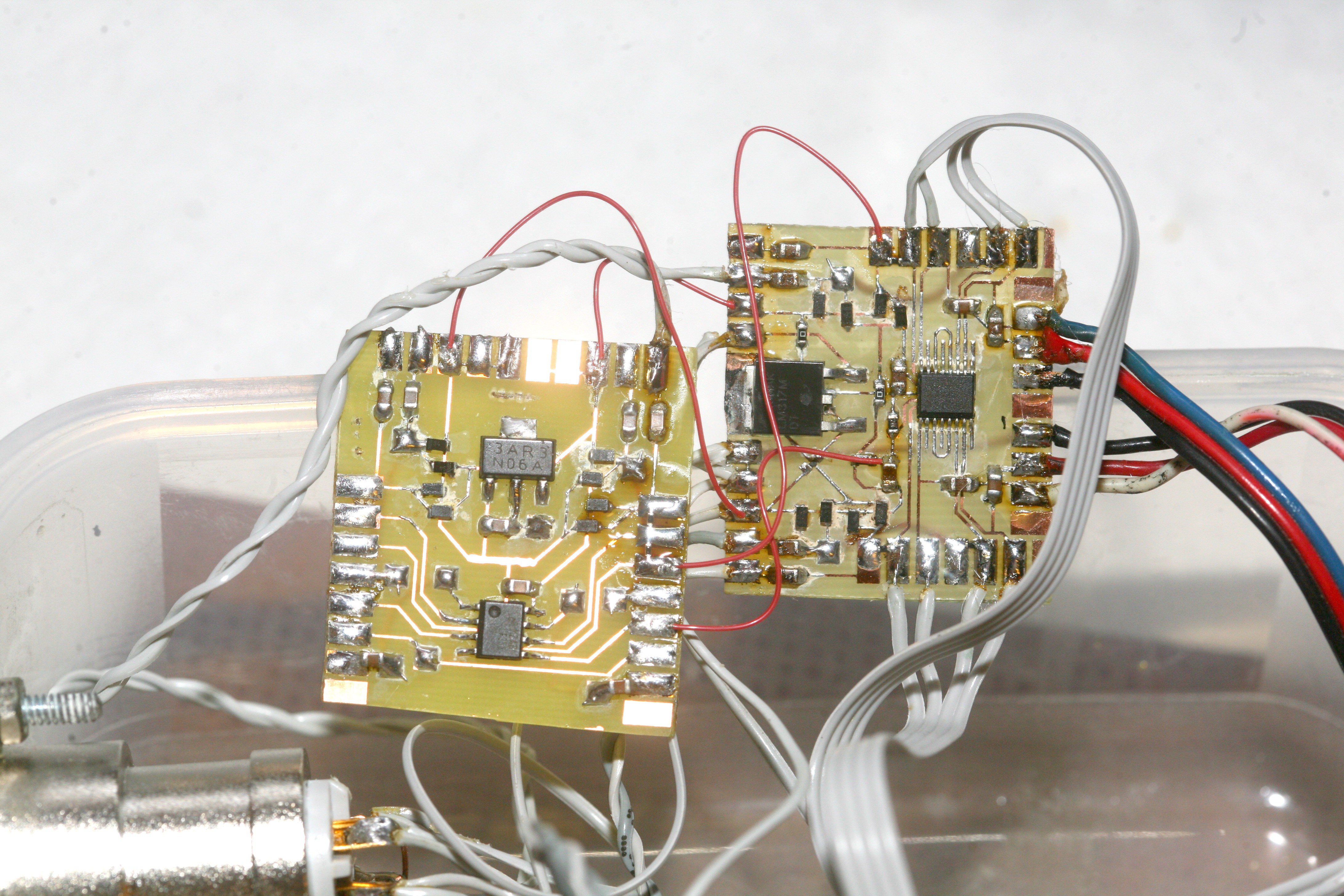
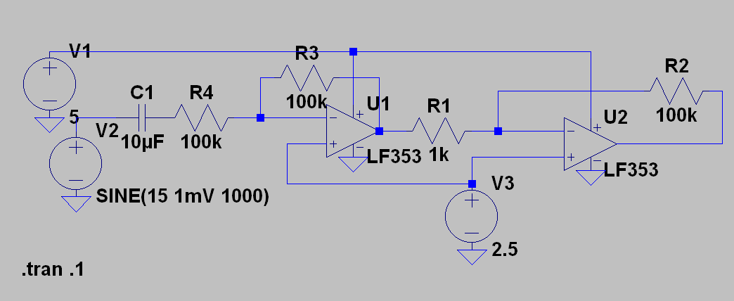
Bodged on a matching amplifier to raise the input resistance to 100k. It actually amplified the noise more.
![]()
It actually increased the noise gain by roughly 7.1x or from roughly 100/7.8 to 100/1. Basically, while the matching amplifier would be like a 100k resistor without an op-amp, the op-amp effectively shorts out the 6.8k, since current no longer flows through it. The 2nd stage went from 1k + 6.8k to just 1k.
If the microphone is specced at 75ohm output resistance, it should overwhelm the noise behind the 6.8k resistor when connected. You still need a 2x or higher stage to get more gain from the microphone.
-
Testing phantom power 2.0
01/21/2018 at 07:34 • 0 commentsGot an LM317 to last long enough to graph this.
![]()
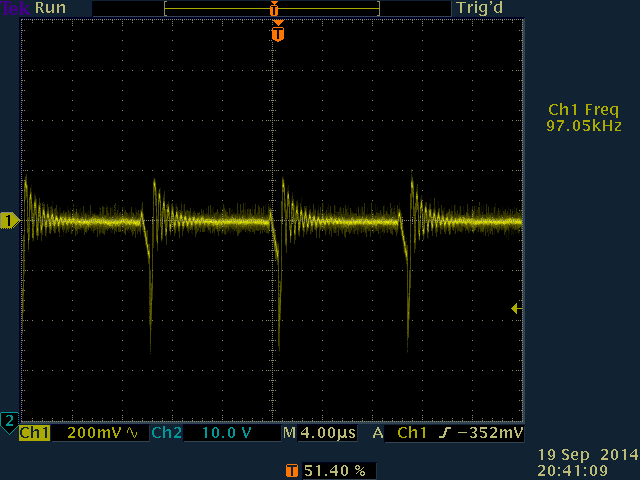
The best control algorithm was an improvement over what was done 7 years ago. 2nd order derivatives & lead compensation were key to getting it just that stable. The problem is, to save space & power on a clock source, the smallest duty cycle increment is quite large. There's also a long feedback delay. The minimum battery voltage is 11V before it maxes out the duty cycle. Had to reduce the frequency to 80khz to get that low. The home made inductor is optimum at 60khz. At 11V, you're getting 100mV more ripple because the LM317 isn't rejecting anything.
There's a video of the booster in action, without lead compensation. Lead compensation added 1V to the floor of the 2 microphone case, but was negligible for everything else.
It would have utterly no effect on the current 96khz ADC with differential pairs, but a better solution is varying the frequency of the inductor rather than the duty cycle.
Providing 12mA to power the LM317 + 2 microphones, it uses 80mA at 12V, so 60% efficiency is achieved. The trick is the LM317 sucks 3.2mA at 48V & the PIC + LED suck 18mA at 12V. The home made inductor is 98% efficient.
![]()
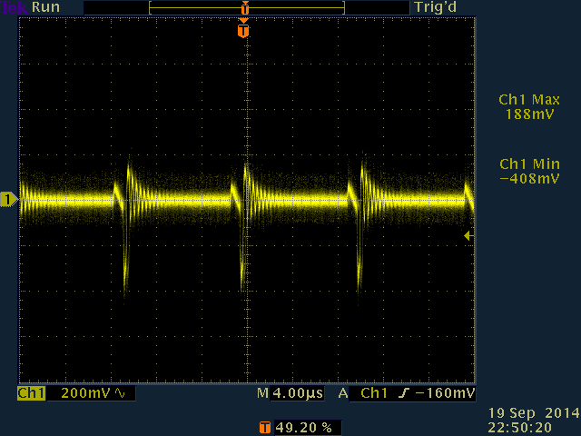
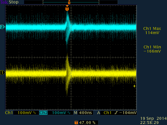
The output of the preamp still had 600mV of ripple. Started to look like a ground loop. Grounded it to analog ground as well as the mane ground. Lifting the mane ground actually increased noise, but connecting both grounds actually reduced ripple slightly.
![]()
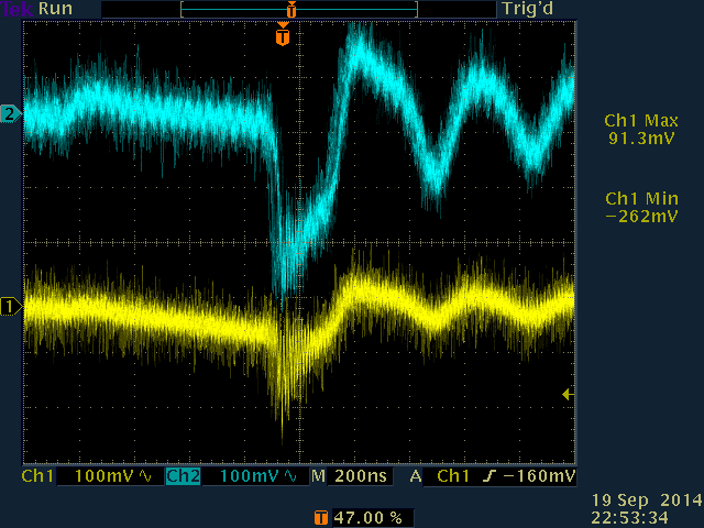
There is asymmetry in the differential pairs, with the wire closest to the debug port showing the most ripple & the wire farthest showing the least.
![]()
Minimum gain reduced the ripple on the outputs.
![]()
![]()
![]()
The final result showed it's a bee's dick quieter than the 7 year old circuit. It actually gets noisier if the phantom power is connected but turned off. The $20 mouser special wouldn't make it quieter.
There's a file of just the normalized noise from down at -77dB. It's beautiful noise.
-
Death of a linear regulator
01/20/2018 at 09:40 • 0 comments![]()
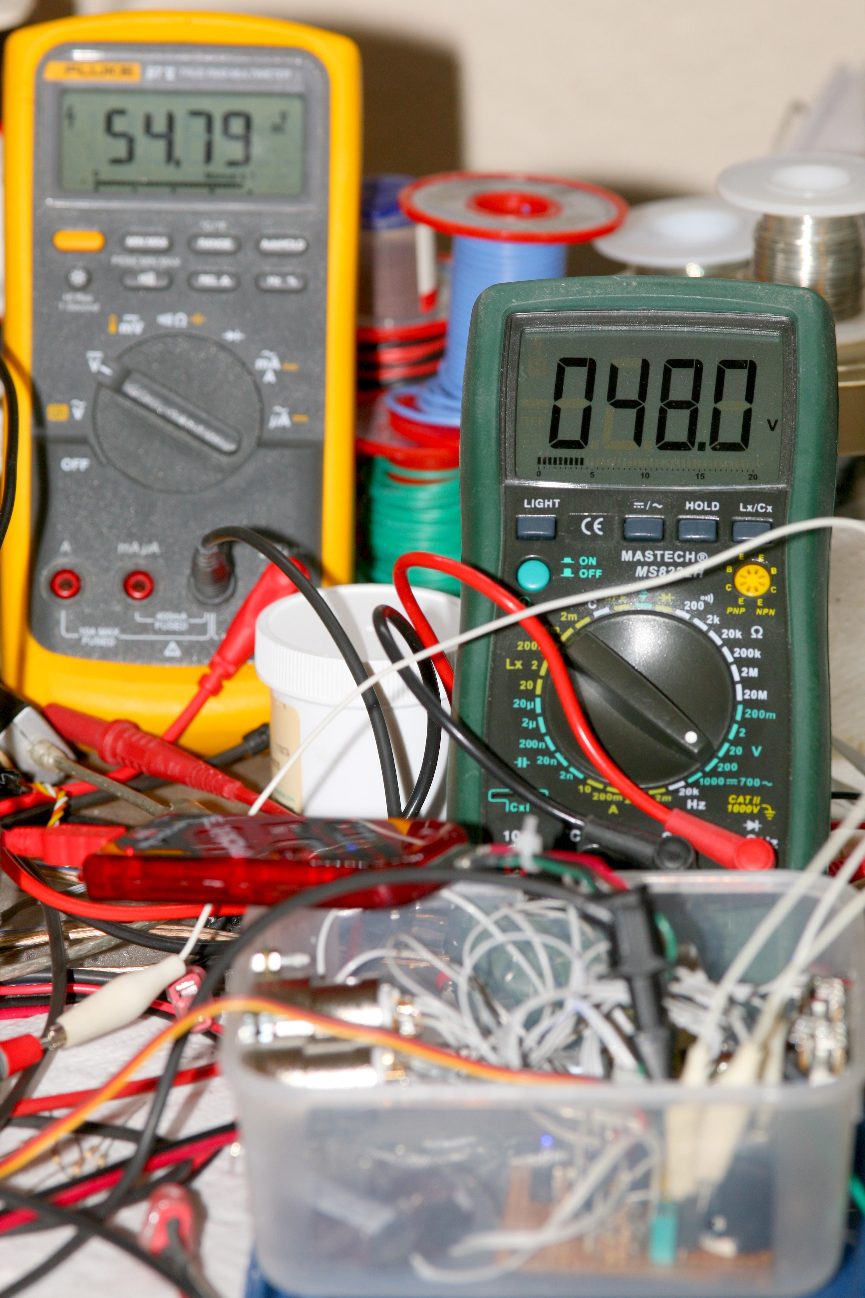
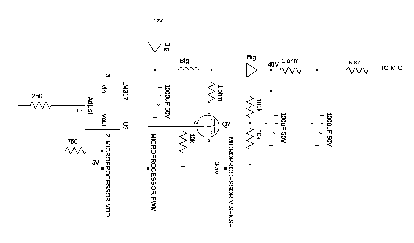
Got the linear regulator to work, initially. The 54V directly from the boost converter can be seen getting converted to 48V. Used a 15k & adjustable 1k for the 48V regulator. They provide the required 3mA load without burning up.
![]()
![]()
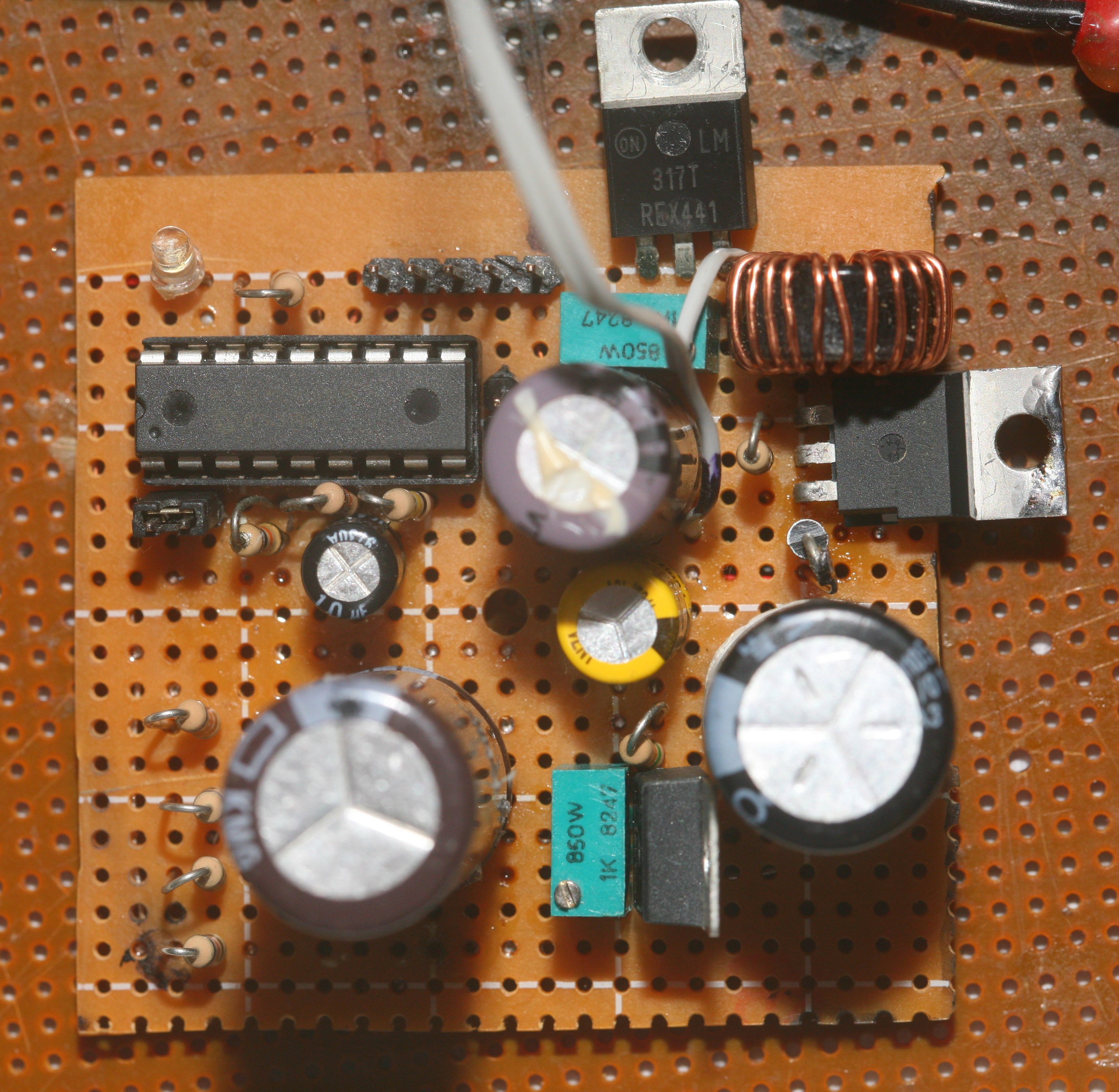
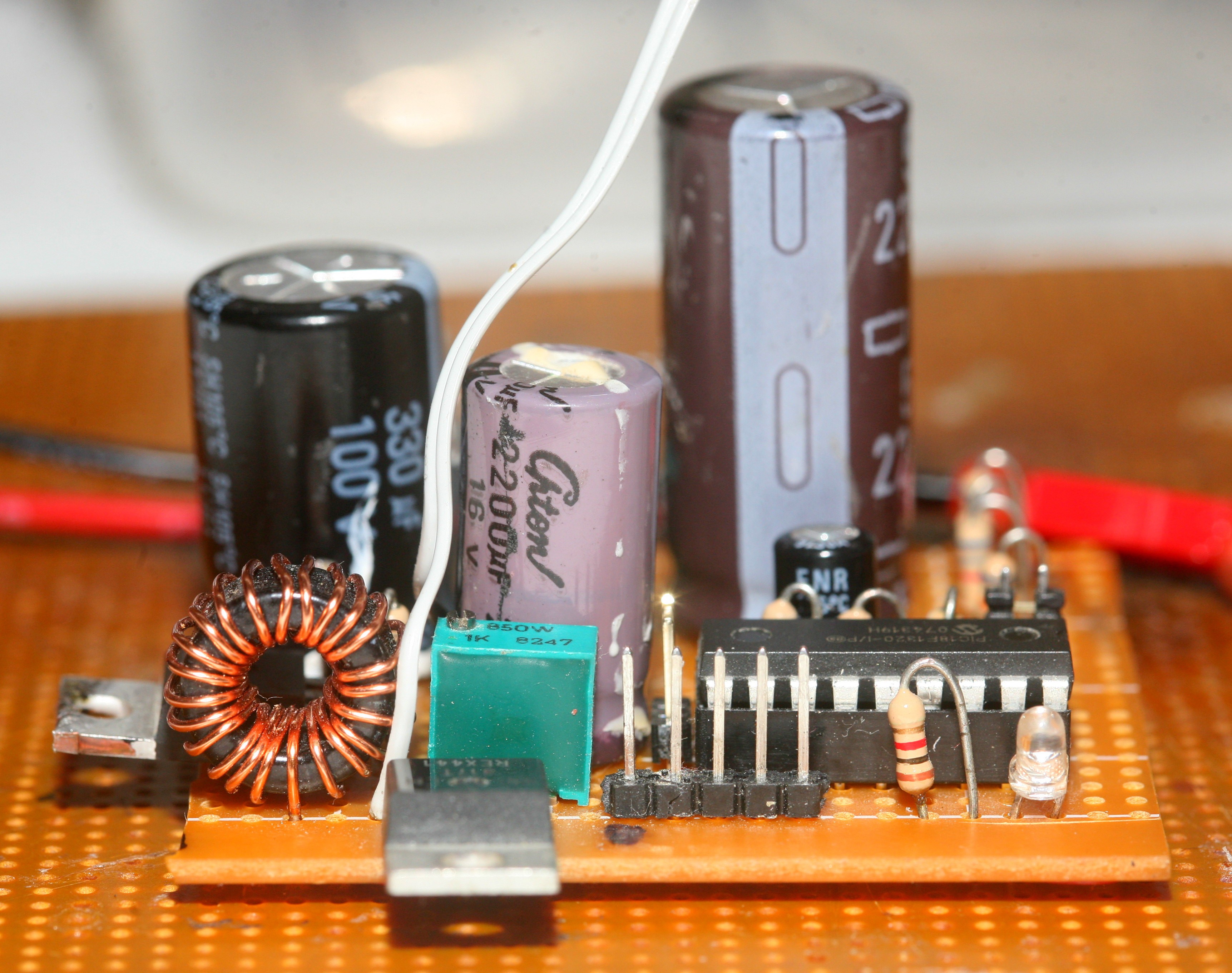
Next came optimizations to provide enough current to the regulator & reduce the noise. The new phantom power board was quite an improvement over the original. All the capacitors which used to be on breakout wires managed to fit on the board. The network of dozens of 10k & 1.7k resistors was replaced by 4 6.8k resistors. The diode was replaced with a shottky. A small resistor to limit current in drain was removed. It's much more efficient. The key enablers were a current limited power supply & oscilloscope.
Every effort was taken to star ground, though there wasn't enough room to get it ideal. The mane concern is separating the linear regulator ground from all oscillating parts. Added a serial port for debugging. The original was debugged without a serial port. The firmware was moved from assembly to C because the algorithm needed tweeking for the higher efficiency.
The original algorithm was an ingenious design to let the voltage swing from 46-50, trimming the duty cycle only when it hit a boundary. Since the biggest source of noise isn't absolute voltage but changes in duty cycle, it was focused more on manetaining a constant duty cycle than an accurate voltage.
Increased the voltage swing to 52-60V. Fired it up & the linear regulator output was now following the boost converter output. A quick test outside the circuit revealed it was the 1st bad regulator in 20 years of soldering regulators.
We have a 0-1k R1 & a 15k R2. The maximum voltage setting is 15k/0 * 1.25 or infinity. The minimum is 15k/1k * 1.25 or 18.75V. The only conceivable fault was if it was set to 18.75V & the boost converter put out 60V, it would just barely exceed the 40V rating. The other way it can exceed 40V is if the output is shorted. It should never short in casual use, since all the outputs have 6.8k's. The thermal protection of the LM317 is legendary, but lesser known is the lack of any over voltage protection. The easiest solution is to add a parallel R2 so it doesn't go above 500 ohms.
-
Next rebuild begins
01/19/2018 at 03:12 • 0 commentsThe ultimate 4 channel audio recorder was the 1st ADC good enough to begin stressing the preamp. Tests showed the phantom power was the largest source of noise. The op-amp & pot were actually below the ADC noise floor.
It was a good thing, because a 2nd op-amp stage might be required to get the microphone to saturate the ADC.
The mane event is of course, the phantom power.
![]()
There was a schematic from 2011. Several years later, a bag of xena diodes was added to prevent over voltage. There weren't any commercial products which did it from batteries. Voltage converters to make 48V out of 12 were expensive & rare, so it was simplest to make a booster out of spare parts. Much effort was spent to minimize the output ripple with passives, but it was still awful. The only reason it worked was the ripple was above human hearing & canceled by the differential pairs, but it does reduce headroom & the differential signal isn't perfect.
Years later, the 1 boost converter at mouser is a whopping $20 + shipping, so the easiest solution was whacking in a linear regulator & seeing if it not only eliminated the ripple but also the noise. Didn't realize in those days that there was no limit to the input voltage of a linear regulator. The only limit is the drop from input to output, so they can actually drop 60V to 48V.
The problem is the LM317 needs a 3mA load to be stable, so you whack in a trim pot for R2 in your LM317 datasheet. A 7500 R2 & a 200 R1 aught to do it & provide 6mA load current. Then, the boost converter fails to get above 24V & is unstable. The problem is at high voltages, R2 dissipates a lot of power. You're lucky to get the 0.5W rating of a trim pot. 48/7700 * 48 = 0.30W Also, the boost converter never reaches 48V with a 6mA load. It's never easy.
-
Microphone schematic
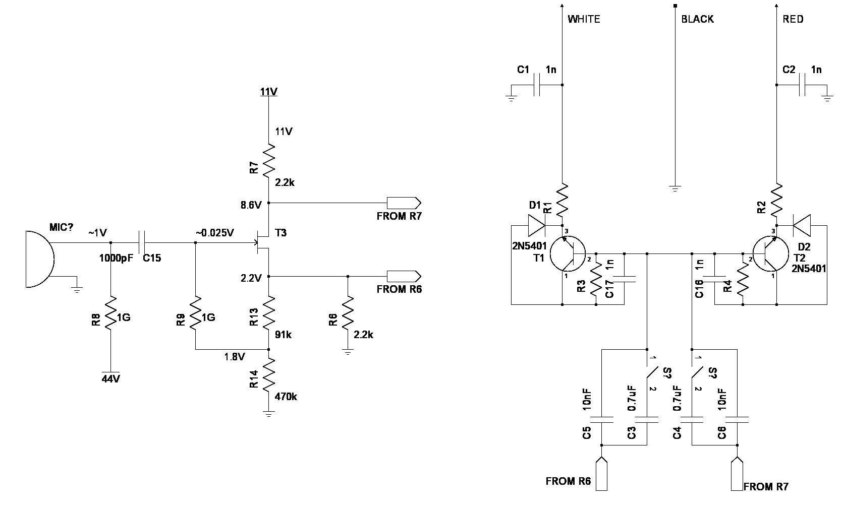
01/17/2018 at 03:57 • 0 commentsStarted a schematic of the CAD GXL-2400 7 years ago. Finally finished the part showing the amplifier section, but not the power section.
![]()
The salient points are the switch is a bass rolloff. Probed the voltages of the 1st stage. From ohms law, we have 1mA going from 11V to ground, through T3. T3 presents a 5.8k resistance in silence. R13 & R14 pass a few uA & R6 passes the rest.
Technically, it's 2.2k + 5.8k + 2.2k in series. When the transistor passes more current, the 8.6 drops & the 2.2 rises. When the transistor passes less current, the 8.6 rises & the 2.2 drops, instant differential pairs.
It would work with just a 12V supply. R7 & R6 could go directly into an op-amp circuit & then an ADC.
There's a decent description of an amplifier very similar to this one, which has a capacitor shunting R13.
Lions long dreamed of powering it off a more reasonable voltage besides 48, but every test says all the components are sized for exactly that voltage. Going lower causes the transistor bias voltages to become unstable & would require a major redesign.
Suspect phantom power is going away & all future microphones are going to be USB with the ADC inside the can. With only brief shopping & very limited specs online, would say the current bottom of the line are 48khz 16 bit USB mics. Very expensive USB mics probably do 24 bit 192khz.
The absolute limit could be considered a battery powered ADC inside the can, with optical output. The problem with integrated ADC's is they all require digital signals inside the can, so the debate between external & internal ADCs probably hasn't been settled.
A ground up circuit to reach line level inside the can probably would be more useful than an external preamp. Having said that, experience with the AK4524 showed no meaningful noise from the digital side but all the noise from sources outside the microphone can. At minimum, it would just need a direct conversion of the I2S data line into a 3Mhz optical signal, a booster to 48V, & a pot sticking out of the can.
 lion mclionhead