Viva Penguinos
-
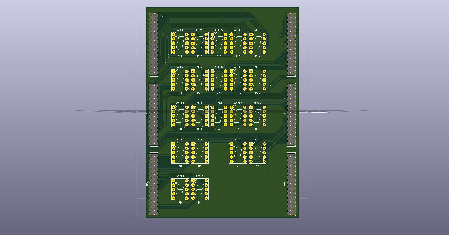
7-Segment Controller Board PCB
08/23/2015 at 18:21 • 2 commentsyI finally bit the bullet after verifying me design and went and ordered them from Oshpark. The reason why it took so long is because is because it costs me $80 per board (Display Driver, 7 Segment Display), and then $40 for the micro controller Board. I haven't even accounted the parts to populate the board. In all it would cost me 200$ just for the PCB and another $70-80 for the parts just to see whether or not the device works or not. Anyways, Enough of the Text, Here's some pictures of the Display Driver board.
![]()
![]() Just note that this project is at a snail crawl because of school and the cost of having them produce but if anyone is interested in buying this board in particular, Let me know in the comments or message me and I'll work something out with you.
Just note that this project is at a snail crawl because of school and the cost of having them produce but if anyone is interested in buying this board in particular, Let me know in the comments or message me and I'll work something out with you. -
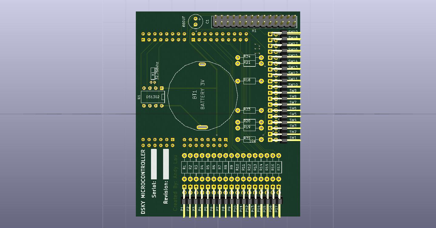
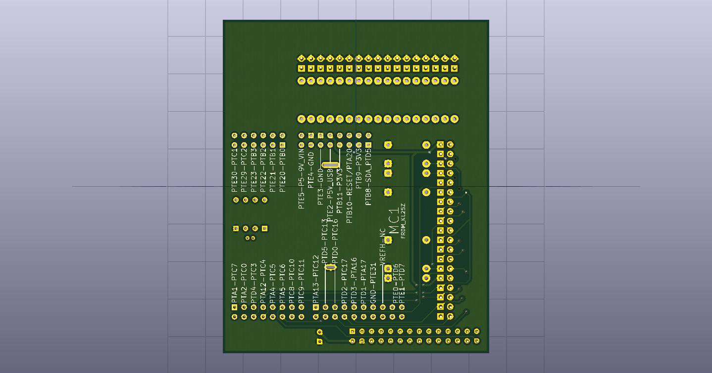
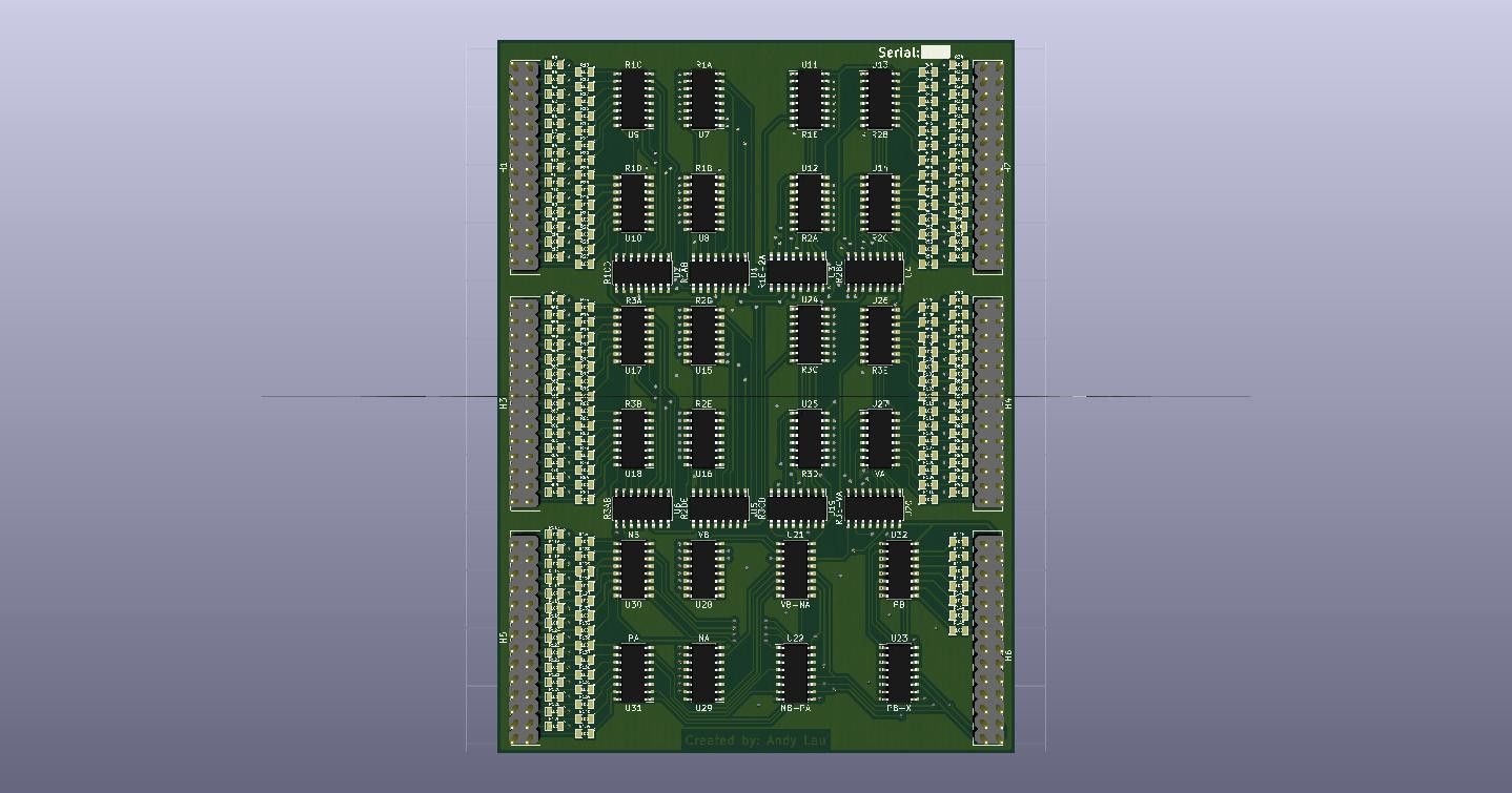
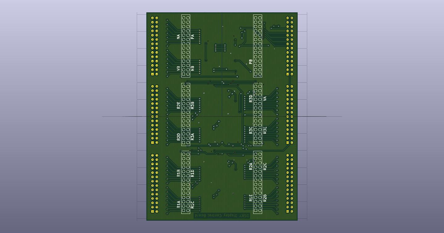
PCB Render
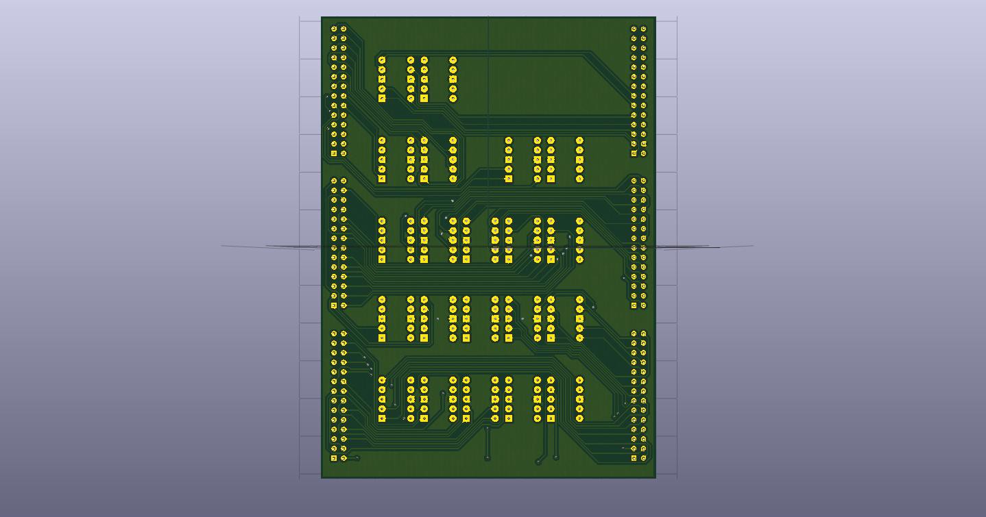
05/04/2015 at 22:49 • 0 commentsHere's the rendered version of the PCB's, I have yet to send it to the Oshpark but when I do, I'm going send the smallest one (Which is the Micro-controller) first to verify that my Layers are done correctly. There is 3 PCB in total, One is the micro-controller, the second is the display drivers, and the last is the 7 segment display. The images will show both front and back for each PCB.
![]()
![]()
![]()
![]()
![]()
![]()
-
Status Update
03/27/2015 at 22:06 • 0 commentsI apologize that I haven't been updating the Open Source DSKY. School started back in August and I've been bombarded with classwork. As of now, the project is currently on hiatus. I've been working on and off on the project when I am on break, or when I have free time. So hope is still there! My last update was 8 months ago and some changes (Even though small) has been made.
Hardware:
PCB layout completed This includes the Display Drivers, The seven segment LED, and the Micro controller board. Had to do 4-5 revision before I was finally satisfied (I am also a newbie so it took much longer than normal). Waiting to save enough money to be sent to the Oshpark.
Software:
New programs has been added to the software, but those has yet to be tested.
Research:
Thanks to my university, The library has papers and books regarding the Apollo System including navigation, power, resource management, and data obtained regarding the CSM.
I'm currently taking a class regarding objective programming in C++ which also includes programming GUI interfaces. The goal is to absorb as much information I can get in that class and apply those skills and create a GUI interface which would allow users to communicate with the device with little to no background knowledge (Which would be great for educational purposes.).
Thanks for hanging in there, I know some wondered what was the current status of the project and whether it was abandoned or not.
-
First Official Video, DSKY Program Breakdown
07/24/2014 at 19:48 • 0 commentsNow with the hardware aspect completed, it’s time to move onto the programming portion. The video below is the current status of the DSKY. If this goes well, I may consider uploading more video update logs.
For people who don't know what is happening on the video, at the start of the video, the micro controllers tells the shift registers to display 8 on their entire screen. It's more for presentation rather than function. After the initialization is completed, the first thing I program into the device is Verb (V) 35. This tells the DSKY to test all the lights to verify that it is in working order. Following V35, The next thing I programmed is Verb 16 Noun (N) 36. This informs the DSKY to display the Ground Elapse Time (GET). The last program is V25N36. This is used to configure GET. Once initiated, the computer notifies the use with code V21N36. This informs the user to input the values for the hour portion of the GET. After the hour has been inputted, V22N36 ask the user to input the minutes. Lastly V23N36 ask the user to program the seconds. Once programmed, it goes back to displaying GET with the new information. The following section is going to cover the programming aspect of the project.
Programming Breakdown:
I'm not going to go in detail with each portion of the code but I will provide a general overview on how I code each of the DSKY program. Before we start, Most of my information is retrieved from Ibibio If you need to refresh or get additional information, go and spend some getting some background. The other source of information is from the Apollo 15 user manual from Delco Electronics. From those three sources, I should recreate the software portion of DSKY.The source code for the project is already uploaded onto the Mbed website. DSKY Code
Test Light Program V35 (Line No: 628 - 661):
Test_Lights() function is rather simple. It starts by configuring all the shift register data to 0x08 which basically tells the 7-segments to display 8. The program then waits one second and configures just the verb and noun to 0x0f which turns off the 7 segments.
Display GET Program V16N36 (Line No: 482 - 554):
This function does involve some math and forethought. The format may not be the efficient way, but it's in a format where I could easily understand what I code. Commenting on the code does help also. The next portion of the code then calculates the time difference and sub divides it for hours, minutes, and seconds. It then displays the values into the shift registers.
GET Configure Program V25N36 (Line No: 673 - 786):
Once this function is initialized, It blinks V21N36 asking for input for the hours category. Then blinks V22N36 asking for input for the minutes, and lastly blink V23N36 for input for the seconds’ category. Once all information is inputted, it then checks whether the value exceeds the maximum hours, minutes, and seconds. If it does not, it then continues by converting both the hours and minutes to seconds. After calculations, it then resets the clock and goes to GET program
-
Wire-Wrapping Milestone!
07/12/2014 at 07:27 • 0 commentsMany things have been accomplished since the last project log. Because of this, I'm going to split this into two project logs. A week after I posted my last project log, I finally received my shipment of 30 gauge wire from china. The order was divided into two packages; the first package just had just a spool of red wire (Not the color I wanted at the time). Unfortunately, the spool was damaged during transit, but I'm not going to complain about it. The 2nd package contained the other 3 wire-wrapping spools I needed. Here’s a picture of the entire spool together (Yes. That is a CD/DVD spool.)
![]()
Hello World!
When I received my wire-wrapping wire, I was anxious for the other package to arrive (I didn’t know when it was going to even arrive, it actually took 2 weeks to arrive). Until then, I used red wire-wrapping wires to just see if I wired my IC and resistors correctly. Here’s how the wire-wrap looks for the first 7 segments. The cable is a mess but I did not intend on making it look clean.
![]()
The more wire I added, the larger mess it became.
![]()
Until the last 7 segment display for R3 was finally wire-wrapped.
![]()
It looks like a small spaghetti monster; I connected my cathode and double checked all my pin-outs from the resistors. Additionally, I verified that all of the IC could handle the same voltage supplied (5V).I plugged in my microcontroller and looked at the 2nd perfboard. This was the sight I was greeted to.
Hello World!
![]()
The process of having an idea from a concept to an actual prototype is one of those feeling that is hard to explain. Seeing that 7-segment LED light up saying “Hello there!” just kept me going to completion. As much as it pains me to remove all wire-wrap, the 2nd package arrived which contained the orange wire-wrapping spool. But before I took it apart, I made sure I wrote all the pin outs for the 7 segment and verified it with continuity so I could just wire-wrap without going back and forth.
More Wire-wrapping!
Since the first row of 7-segment worked, I decided to just wire-wrap the project in one go. Knowing that Murphy’s Law may strike again, I went and wrote all the pin-outs where the shift-registers connect to including the pins on the 7 segment drivers. I Doubled/Tripled checked the pin outs with continuity before I continued. This would be the last time I have a known working configuration. If I screwed up here, it would be a major hassle to fix the problem should it not work. I call this, Murphy’s sticky note.
![]()
I continued with wiring R2’s shift-registers tying with R1 shift registers. The white wire-wrap indicates shift-registers to BCD decoders. The blue indicates BCD decoders to resistors. I used a spare wire-wrap IC to make sure all the wires are routed in the proper way.
![]()
Here’s the front side of the perfboard. Remember that each shift-register can accept 2 BCD decoders. So I have 5 shift-registers driving 10 BCD decoders each powering one row of 5 7-segment displays. The amount of repetition I have to make is astounding. But headphones and having music makes this relaxing.
![]()
Wire-wrapped R3’s 7 segment displays, this was one of the trickier one to place since it overlapped both R1 and R3 wire bundle. I quickly learned that the toothpicks from wallyworld fit nicely between the pins. After spending some time wrestling the wires, I managed to complete it.
![]()
Here’s the top side of board. Note the placement of one set of resistors. It's placed differently because R2's wire bundle is in the way. Refusing to re-wrap R2 again (Yay Murphy’s Law!), I decided to just suck it up and place it in a way where I could make the other resistors look somewhat consistent.
![]()
Here’s a close-up of some of the wire-wrapping job, more “artistic” images below!
![]()
![]()
Unfortunately (For my readers, a relief.), the images I have for the Verb, Noun, and Program numbers were blurry, or I had forgot to take them (Didn’t take images for Noun, and Program, Verb was Blurry).
Mounting time!
After finishing wiring shift registers, BCD decoders, and resistors it’s time to mount it on a somewhat solid frame so I can move it from different places. I passed by the local craft store and brought 12inx12in birch plywood board (304mmx304mm for metric people). Drilled some mounting holes and doubled up on computer standoff for the proper height. Here’s how it looks like.
![]()
I mounted the perfboard backwards so I can work on it effectively without worrying about it moving. Here’s how it looks like during the wire wrapping process.
![]()
I still can’t get over how well it looks when you properly route the cable and making sure there is little or no slack. Here’s a close up of it.
![]()
I continued wire wrapping the 2nd row and things started becoming more difficult organize. After some trial and error, I found that the tweezers I’ve been using provided good amount of pressure to hold itself in place without bending the pins.
![]()
The two images below are close up of R1 and R2 wire route.
![]()
![]()
I removed the wire wrap IC I used for routing R1 and R2 wires so I can move it in preparation for R3, Verb, Noun, and Program Number. To prevent them from shifting too much, I tied it at certain intervals to make sure the wires are bundled together. Then I proceeded to wire wrap R3’s. I shifted the wire wrap pins by one row so I can have space when I route things, a move that proves to be very useful soon.
![]()
![]()
Again, I forgot to take pictures of me wire wrapping Verb, Noun, and Program but no drastic changes. Nearing the end when I was wire wrapping the Noun and program, the cable kept popping out of the IC pins because it kept going above the pins. One change I made was moving the connector from a 5 pin to a 20 pin connector so I can make it look like a clean prototype. This again proves very useful when I went to add additional components. Even though it was a pain in the butt to move the connector, I managed to get it assembled.
This concludes the end of my wire wrapping adventure and this project log. You’ll see more in the next project log. It’ll be written up once I release this to the public. I’ll leave you with some additional pictures; A few comments must be made. First is that the keypad and RTC was added a few days later when I was programming and working on it. The next build log will contain mostly code and what features I’ve manage to get working (maybe a video? :D).
![]()
![]()
![]()
![]()
![]()
-
Wire Wrapping Zen, AutoCAD-Inventor, and CNC fun!
06/08/2014 at 05:59 • 0 commentsPackage Arrives!
So I received my package from Newark on March 25th. Here are the new goodies that I got:
![]()
One thing which I did not expect was the reel of resistors. Previous packages came only in a cardboard box with some foam. No matter since I can always reuse it to spool some wire onto it. This is my third purchase I made since started this project. Hopefully that is the final purchase I have to make to Newark for electronic parts.
Wirewrapping Zen:
Before I started wire wrapping, I populated my prototype board to see how many Wire wrap IC I would need to place. Additionally I had to figure out the area it was going to occupy including the wiring route. The image below shows roughly how much area both shift registers and the BCD decoder occupies.
![]()
After spending an hour or so learning how to properly wire wrap, I have finally found the Zen that is of wire wrapping. Here are some recommendations for people who never wire wrapped before (As I’ve made them).
- Plan your cable route
- When wire wrapping keep your tool rotating the same orientation (Decide whether to do Clockwise or counter clockwise). You don’t have to mess around determining whether it’s wrapped clock-wise or counter clock wise.
- When placing components, Leave a row or two of holes to allow for cable routing
- If possible, designate different color wires for different categories. Makes it easy to troubleshoot and makes your board look colorful (And who doesn’t like that.)
- When wire wrapping, Try your best to keep the quality of your wire wrapping high. Makes troubleshooting easier. You’re not happy about the wire wrapping on the leads, Re-do them.
- Try to wire wrap in an area of good lighting. (I use under cabinet CFL with 4100K bulbs that I picked up at wally-world (Wal-mart))
- Listen to your favorite choice of music and enjoy the Zen of wire wrapping.
Before someone call out some of my recommendations, I did try to follow some of my recommendations but Murphy ’s Law may have prevented that on certain occasions.
The way I have my wires color coded is:
Red – Positive Rail
Yellow – Negative rail
White – Signals between Microcontroller to Shift registers and BCD decoders
Blue – Resistors to BCD decoders
Orange – Resistors to 7 Segment Displays (Future)
Here are some shots of my wire wrapping as I progressed on.
Initial start of wire wrapping:
![]()
Close up of the initial wire wrapping:
![]()
![]()
Close up of the interface pins to connect to the Mbed controller. Currently I’m using 2 for power, 3 for signals. Leaving 3 pins left for future expansion. Should I Need more I’ll replace it with the smallest wire wrapping connector I have.
![]()
After I finished wire wrapping the shift register and the BCD decoder I moved towards wire wrapping the resistors. Here it is after wire wrapping two of the resistors. The graph paper you see in the background is the physical layout of the IC and resistors.
![]()
![]()
Another image when I completed wire wrapping resistors for 2 BCD decoders.
![]()
Close up of the same progress. Notice how all of my wires are spinning in a certain direction?
![]()
Here’s the “Final” picture after I wire wrapped all the resistors to its perspective BCD decoder. The reason on why I said it was the final was because I made a mistake. That mistake wasted time and effort into this project thus leaving my recommendation of leaving a row or two of holes for cable routing. All the blue wiring was actually putting pressure onto one of the pins of the wire wrap IC, Bending it slightly. So I had to unwrap every wire and re-do those so it isn’t putting pressure onto the pins (Hence another recommendation of rotating the tool the same orientation for every leads. I do not have any images of the 2nd attempt of cable routing but you’ll see the difference in future project logs.
![]()
Close up shot between the BCD and the shift registers:
![]()
Close up shot of the resistors (Loving my cable routing honestly):
![]()
Macro shots of the resistors and the Wire wrap IC (You can see I am proud of my work)!
![]()
![]()
![]()
![]()
Front shot showing the Shift registers, BCD decoders, and Resistors.
![]()
CNC fun!
Remember previous project where I showed the front panel of the DSKY using AutoCAD? Well I converted the drawing to G-code using CAMBAM (Wanted a simple and inexpensive software to where I can get my hands dirty producing g-code) The CNC computer uses LinuxCNC cause I couldn’t justify purchasing MACH3 (Plus, GO OPEN SOURCE!). Eventually I do plan to release the drawings but I will not release the source code for G-code. If you must ask, I’m not going to release G-code since each CNC is different between models, make, and homemade. My G-code works for mine, could work for others, but most often or not may not work for their CNC. Feed rates, Speed, Spindle RPM determine how well the machine operates with a given material. Since I’m already planning to release a full set of drawings for anyone to replicate, you can just easily pop it into your favorite CAM software and have the computer produce the G-code for you.
Here’s a shot of the CNC cutting the front panel out of foam board:
![]()
Close up shot of the CNC cutting the button slot.
![]()
The image below is the completed run of the front panel. It’s not perfect and I’m sure I could optimize it. For one, The CNC didn’t cut through the foam board requiring me to cut it off. I also had to add thickness on the bottom portion of the panel because I lost support in that area. In the end, I decided to scrap it and I do plan on remaking the panel.
![]()
AutoCAD-Inventor Fun!
Since I ran out of wire wrapping wires, I ordered some more off Ebay from china. It’s going to take 2-3 weeks before it arrives and I can continue working on the electronic portion. Until then I started trying to make the original DSKY case using AutoCAD and assembling it with Inventor. I’m not going to lie, I took the design and measurement off EduCraftDiversions. If you’re into space gear and working with craft specifically paper craft I do highly recommend their products. I purchased mine off ebay (Link: http://www.ebay.com/itm/LM-5-DSKY-DISPLAY-KEYBOARD-APOLLO-GUIDANCE-COMPUTER-AGC-MODEL-ART-CRAFT-KIT-1-1-/230953345011?pt=LH_DefaultDomain_0&hash=item35c5e45ff3) their official site is http://www.educraftdiversions.org/Default.asp. I did tweak the design a bit to make it structurally sound for Birch plywood and ease for assembly.
Front Panel:
![]()
Side Panel:
![]()
Bottom Panel:
![]()
That was just for the front panel itself. The next series (More than the images shown above) are the Main front housing to hold the DSKY front panel itself.
Front Housing Bottom
![]()
Front Housing Display Panel
![]()
Front Housing Display Pins
![]()
Front Housing dual Holes
![]()
Front Panel
![]()
Quad Holes
![]()
Quad Holes side
![]()
Front Housing Top
![]()
Front Housing Base Board
![]()
The next image is how the pieces are meant to be assembled. My original plan during the design to have it cut out of a laser cutter. For prototyping, I’ll be using my homemade CNC machine.
![]()
Conclusion:
I decided that posting a monthly log would be best suited to where I can work on my project and have time and effort into writing these project logs. Typically it would take me an hour or two writing it then leaving it alone for a day or two to proof-read my project logs. I hope that most of my explanations are making sense logically and are grammatically correct. As of this post, I only received one of the 4 wire wrapping spool (I ordered different color to make trouble shooting easier) I also brought a 1/16” (1.6mm) router bit for me to cut birch plywood with. I haven’t done any programming since last project log so I have nothing to update in that regard. If you like to contribute to the project feel free to leave a comment on the project page and I’ll try to get back to you when I have a chance.
-
Wire Wrapping Adventures, Hackaday's Space Contest
04/29/2014 at 05:54 • 0 commentsSorry for the Long pause in my project logs. To make it up, I’ll post a long project log from then until the day of this project log so you can catch up.
Seeing that I'm running out of space on my breadboard, I’ve decided to take a look into wire wrapping. Interestingly, The DSKY on the Apollo mission also used wire wrap for the back panel. Wire wrapping this project would be a pay a great tribute to the DSKY. I've considered producing a one off custom PCB but wasn't viable in its current situation because of its early stage. After going to a ham fest in Orlando, I picked up one of these babies for $20.
![]()
Not a bad deal considering the current value of these items if I were to purchase them off eBay used. Here are some additional photos showing the contents of the box.
![]()
![]()
![]()
![]()
Wire wrapping tools are nice and all, but it's useless if I don't have wire wrapping sockets for IC's. I purchased a grab bag of Wire wrap IC's for $15 from a friend of mine.
![]()
He also threw in some connectors he found at last minute prior to shipping which I find. There may be a possibly planning on implementing them in the near future. Based on what I've research it is to be used along with a back panel connector. My second theory is that it could be used with ribbon cables.
![]()
Internal Clocking Issues:
I'm having issues with the Internal KL25Z RTC. After trying several times to getting the internal clock working, I've decided to purchase an inexpensive RTC clock. After looking at a few RTC modules, I specifically chose the DS1302 since the libraries were already available on the Mbed official site. After spending an hour or two, I managed to get it working and was able to integrate it along with the keypad. Here’s some picture of the RTC, the micro-controller, and the keypad.
![]()
![]()
I placed an order at Newark on 4/22/14 to complete the R2, R3, Verb and Noun Displays I also brought a Vector Electronics 8016-1 prototype board so I can use it along with my Wire wrapping IC. Total amount came up to 77.14. Eventually in the near future I do plan on having it properly mounted on a wooden board so I can move it around without fearing the wires coming loose.
DSKY Software:
A lot of progress has been made with the software end of this project. I personally feel that I’ve learned more programming by applying it to a project then what I learned in school/college (Cplusplus and Mbed helps out too.). For those who wanted the source code to replicate this project. It is available here: http://mbed.org/users/VivaPenguinos/code/DSKY/ I’ll eventually add more content into that page since I have yet to fiddle around with the platform. The project is FAR from being done. But I’ll continue releasing new revision from time to time.
DSKY Case:
I brought some foam boards for $1 at a local store. My Intention for the foam board is to replicate the original DSKY as close as possible. Here’s the screenshot of the progress so far. It’s in it’s 2nd revision and I still plan on having much more revisions.
![]()
I wasn’t originally intending on posting this considering that I’m using proprietary software. But the only CAD program I’ve ever used that I personally enjoyed is AutoCAD. I’ve been using AutoCAD on and off for the past 8 years. I do not intend to switch to software that isn’t an Autodesk product. I still intend on trying release my drawings in a format that are compatible with most Open Source CAD software (If not, PDF format with proper measurement). But I personally enjoy working with AutoCAD and will continue using them. /end small rant
The Hackaday Prize Contest:
With the recent news about Hackday's Contest, I've decided to join in with the competition. I truly wish the best for everyone who applies to this contest. I'll be keeping an eye on a few projects; as I've truly enjoyed reading many of them.
Conclusion:
Hopefully this project log makes up for the long pause in project logs. This project has slowly been getting more followers. I want to thank everyone for following my project. If you want to contribute on this project, feel free to leave a message on the project. If you’re dying to contact me feel free to contact me on my Mbed’s profile. Link: http://mbed.org/users/VivaPenguinos/
-
DSKY - The Beginning
03/17/2014 at 23:55 • 1 commentDSKY - the Beginning
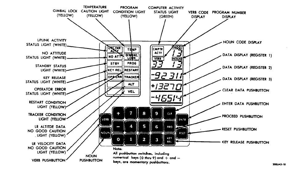
So that everyone is on the same knowledge level, this section will cover basic knowledge of the DSKY. The image below is the front interface of the DSKY. (Source: The Apollo Operations Handbook)
![]()
As you can see, the DSKY consist of three data displays. From this point and on, I’m going to refer the data displays as R1, R2, and R3. Furthermore, the DSKY consist of two 7 segment referred to as Noun and Verb. And lastly, the DSKY also contain program number allowing astronaut to know what program the astronauts are on.
Additionally, the DSKY consist of 19 buttons. Labeled as 0-9, Verb, Noun, CLR, PRO, KEY REL, ENTER, RESET. Most of these buttons are self-explanatory but I’ll cover that in future topic. In the upper left there are activity lights letting astronauts some additional information should they need it.
In total the DSKY contains 21 - 7 segment LED's, and 19 buttons. There is much more to explain that aren’t present in this project log. Should more information be explained, I'll be glad to dedicate a log just for the hardware and software of the DSKY.
Choosing the ideal micro controller:
nitially, I started working on this project with an Arduino Uno. Some consideration to using an Arduino Platform was ease of use, programmability, open source, and large community support.It worked initially for testing the proof of concept but then suddenly I ran out of available IO pins. Deciding whether to upgrade from the Arduino Uno to the Arduino 2560, I later decided to find a platform that isn’t based off the Arduino (didn't really like the programming software). After researching, someone suggested me to try the MBED platform. After checking their official site and the platforms that are available, I decided to purchase the Freescale FRDM-KL25Z mainly for the amount of IO pins that are available (In case I plan on adding additional items). The board came in a rather interesting package.
![]()
After spending several hours of converting code from the Arduino to the MBED Platform, I managed to get the shift registers to blink the displays on and off. Eventually I do plan on cleaning and optimizing the code for readability and efficiency (My programming skills is mediocre).
R1, R2, R3 Displays:
While contemplating on how to go with this project, I decided to start the project with displays for R1, R2, and R3. To minimize the amount of pins required (which would be absurdly large) I decided to use a BCD – 7 Segment Decoder. This allows me to drive one segment with just 4 pins (Compared to driving it directly with 8 pins). To reduce the amount of pins required I added shift registers into the design. This allows me to theoretically drive as much 7 segment LED with just 3 pins. There are other ways to drive it (IE: Multiplexing) but after weighing the pros and cons. I liked the idea of driving it with Shift Registers to BCD decoders to the 7 segment LED.Initially I purchased a small amount of parts to make sure the theory worked. It started with just 3 out of the 5 segment LED. After prototyping it on a small breadboard I suddenly realized that I ran out of real estate. So I decided to upgrade my breadboard and this is how it looks in its current state
![]()
Eventually I’ll have to upgrade to something much substantial if I plan on having all the display shown on the DSKY. More on that in the next project log.
Matrix Keypad:
Another critical part of the DSKY is the Keypad. Since the DSKY has 19 buttons, I went on eBay and brought a small cheap 4x4 matrix keypad for $2. That will allow me to have 16 buttons leaving 3 buttons left to complete the DSKY. Using the source code from HM Yoong (Source: http://mbed.org/cookbook/Keypad). Programming was rather simple (Needed to change some of the code to match the KL25Z). Attaching it was rather difficult. After spending several hours troubleshooting (I don't have a scope to troubleshoot), I managed to get the keypad working by using a pull down resistor configuration. Here's a Shot of the Breadboard with the micro-controller and Keypad attached. Excuse the Header and machine pin configuration, that’s what I had on me
![]()
Final comments:
I'll try to keep this short and to the point. I'll try to keep you updated with new progress. I work on this project on and off depending on what I need to accomplish in my daily life. It really depends on how far I am in terms of software or hardware. I do plan to release the source code for the micro-controller through either the official MBED website or github (again my programming skills are pretty mediocre). If you want to contribute to the project, leave a comment and I'll get back to you as soon as possible.
-
DSKY - An Introduction
03/06/2014 at 00:48 • 0 commentsHello HaD members!
I'm no writer nor professional commenter/blogger/vlogger/<Insert Terminology here>. But the goal of this project is to create a working model of DSKY. For people who aren’t familiar with the DSKY, The DSKY is a front interface that astronauts used to communicate with the Apollo Guidance Computer (AGC). Essentially, it’s the keyboard and monitor to the AGC.
How the project got started:
The project started as an inspiration from a website a friend had sent me. Source: http://apollo.spaceborn.dk/dsky-sim.html wanting to get into electronics and microcontrollers, I thought this would be a nice project to tackle.
Information regarding DSKY
After researching for countless hours, I stumbled upon several sources of information that will be the basis of this project. The first source comes from NASA directly (Go NASA!). Source: http://www.hq.nasa.gov/alsj/a15/A15Delco.pdf The PDF cited is basically the “manual” to the DSKY. It provides all the Programs, Sub Routines, Verb, and anything related to DSKY itself. The second source is from Ibibio. Source: http://www.ibiblio.org/apollo/index.html if you have spare time, I highly recommend you spend some reading time on this particular website. It provides all information for DSKY, AGC, AGS,and the LVDC. Additionally, The author is still looking for more information and documentations to add into the website.
And so the adventure begins…
Actually the project started back in November immediately after completing my last college course in Networking and Communications Management. The first order was actually placed on November 13 2013. As I progressed on with my project, HaD project was released to the beta testers. Seeing this as a project that some tinkerer hacker would enjoy reading or contributing, I decided to hop on the list. Today I received that email and signed up immediately. And now this project is availiable for any readers of HaD. I apologize for the lack of pictures but I’ll guarantee the next post will contain more picture of my project.
Feel free to comment and add any contribution to this project.

 Just note that this project is at a snail crawl because of school and the cost of having them produce but if anyone is interested in buying this board in particular, Let me know in the comments or message me and I'll work something out with you.