Close
0%
0%

Maytag Neptune Motor Control

The PWM signal going to the motor speed control board is basically a square wave with a variable pulse width to control the speed.

Similar projects worth following
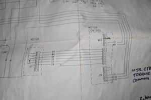
I checked the signal on the control line for the motor speed control with a scope and recorded it, then I was able to duplicate it with a signal generator. It's basically a square wave running at 130 Hz with a variable pulse width that ranges from about 5% for a slow idle to over 90% for a fast 1000 RPM spin. The amplitude of the signal is about 7 volts so it's not TTL, probably CMOS, but a 5 volt signal will work. If the pulses get too low in amplitude the motor stops however. To start the motor in a clockwise direction you have to force the signal line to ground then apply the pulses to make it speed up and run. To reverse the motor first slow it down to a stop with very narrow pulses then force the line high for an instant then start the pulses again to speed it up. I think a simple circuit to do this can be made with a 555 timer chip and a couple of push buttons to change directions.

I found a simple 555 based oscillator circuit that has controls for adjusting the frequency and pulse width that should be able to operate the speed controller on Electro Schematics.  They have both the parts list and circuit board layout to use for making one.  You can also buy a ready built unit on Ebay with a display showing the frequency and pulse width on a small screen for $3.50 that uses push buttons instead of rotary knobs.

http://www.electroschematics.com/5834/pulse-generator-with-555/  
https://www.ebay.com/itm/PWM-Pulse-Frequency-Duty-Cycle-Adjustable-Module-Signal-Generator-LCD-Display/352174283499

MaytagSpeedControl.ino

Arduino sketch that generates a 133 Hz PWM signal for speed control running on Arduino Nano.

ino - 484.00 bytes - 01/10/2018 at 03:22

Download

  • Older and Newer Motors Compared

    Steve02/05/2018 at 19:10 0 comments

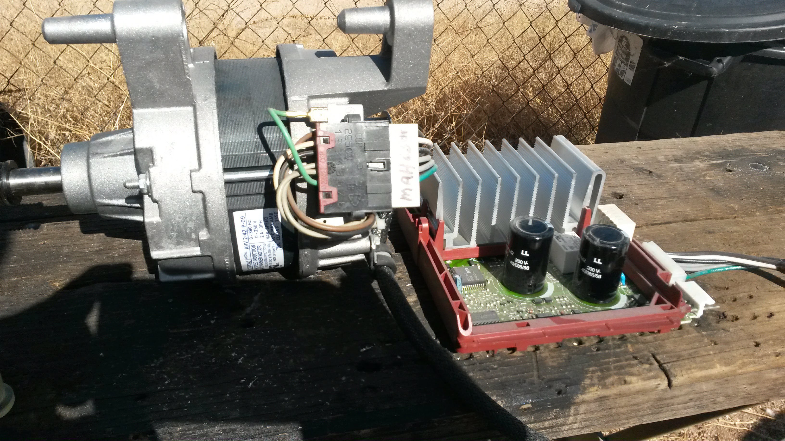
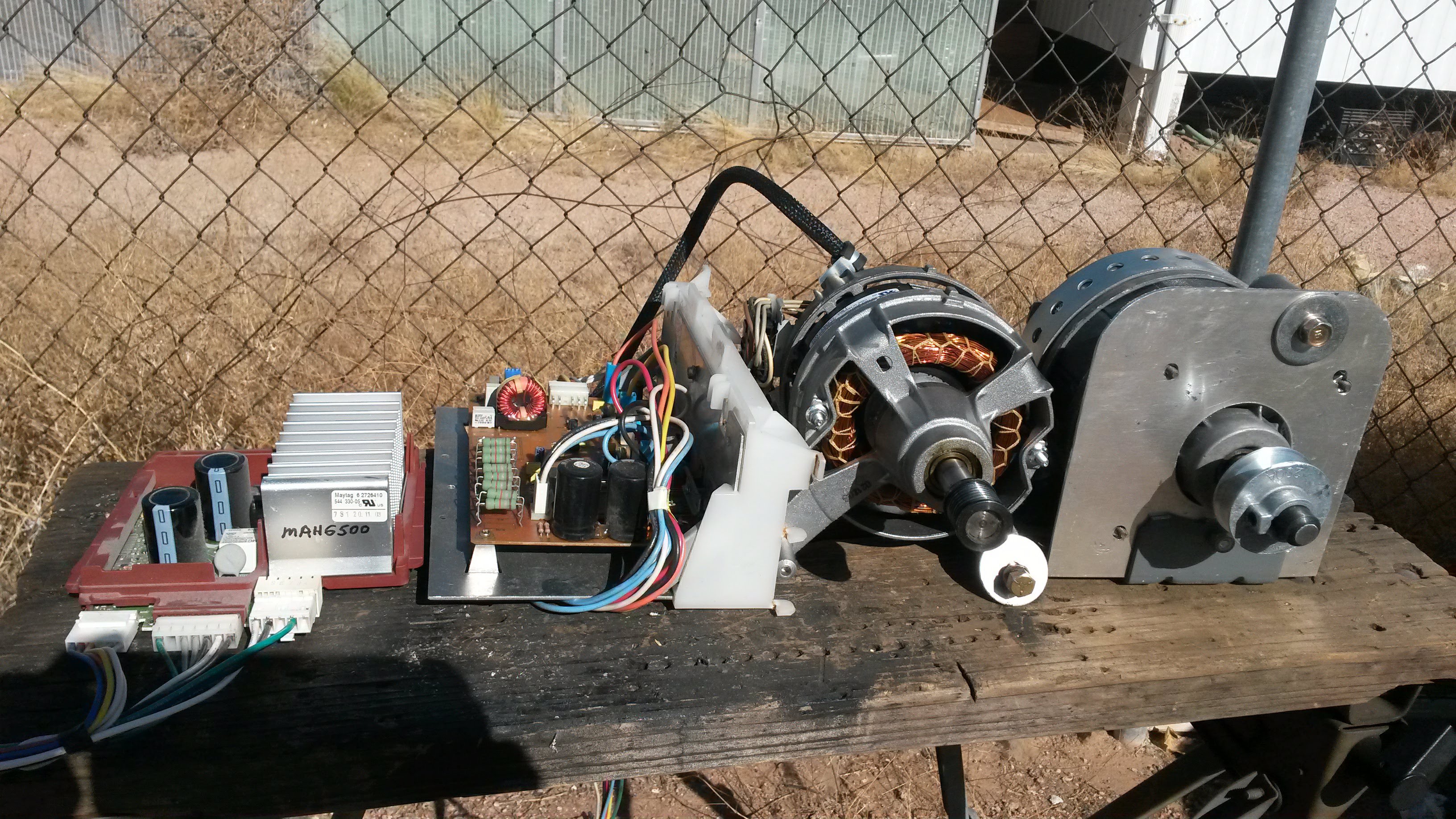
    Here are the older motor and controller from the MAH4000 on the right compared to the newer ones from the MAH6500 on the left.  The MAH6500 uses a motor made in France with a label saying 2 A., 3 Phase, Variable Speed, 0-250 Volts, 0-380 Hz.   The older motor has a 17mm shaft while the newer motor has a 15mm shaft.  There are no specs on the older motor but the service manual says it has an 850 RPM top speed using 400 Watts. For the newer motor the manual says it can spin to 1000 RPMs.  Both speed controls will work with the same PWM signal using an Arduino or signal generator to produce the PWM signal to control the speed. 

  • Newer Maytag Models Won't Work.

    Steve02/03/2018 at 19:31 0 comments

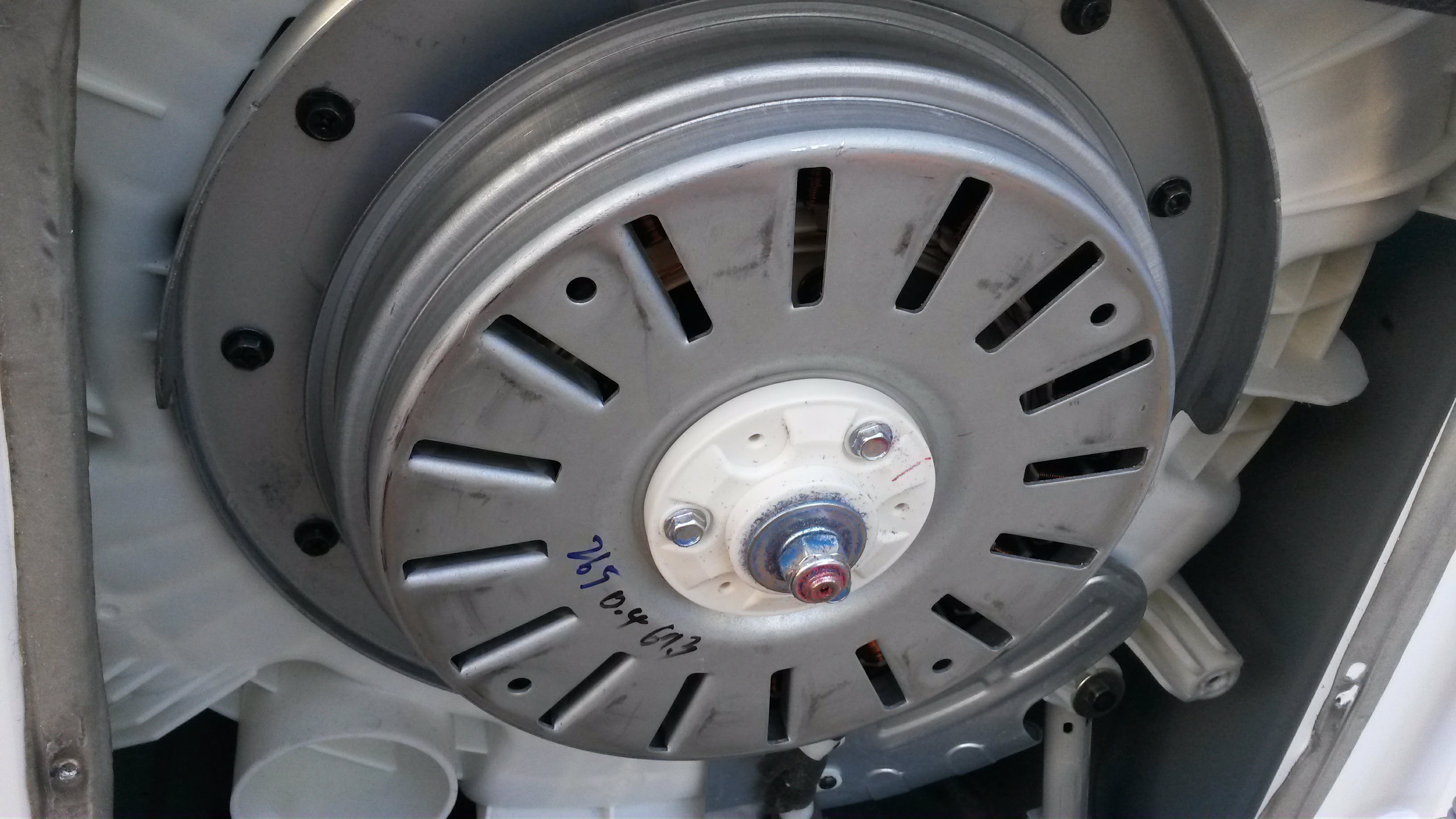
    None of this will work with newer models like the MAH9700 that has a pancake motor mounted right on the back of the drum and I think the speed control in inside the front control panel assembly since all the cables go into that.  The first one I had was the MAH4000 with the old mechanical timer that you turned with a big knob that had a large motor with speed sensor on it hanging from the drum and fairly large motor control module mounted below the motor. They changed the design a lot over the years though and the model MAH6500 with LED display at the back has a smaller motor made in France with a really compact speed control module.  The newer MAH9700 with the controls at the front is made more like a Whirlpool since the drum looks the same and must have had a lot of influence from them when they were taking over the Maytag company although the machine was assembled in Korea by Samsung.

  • Motor Mount

    Steve01/22/2018 at 17:00 0 comments

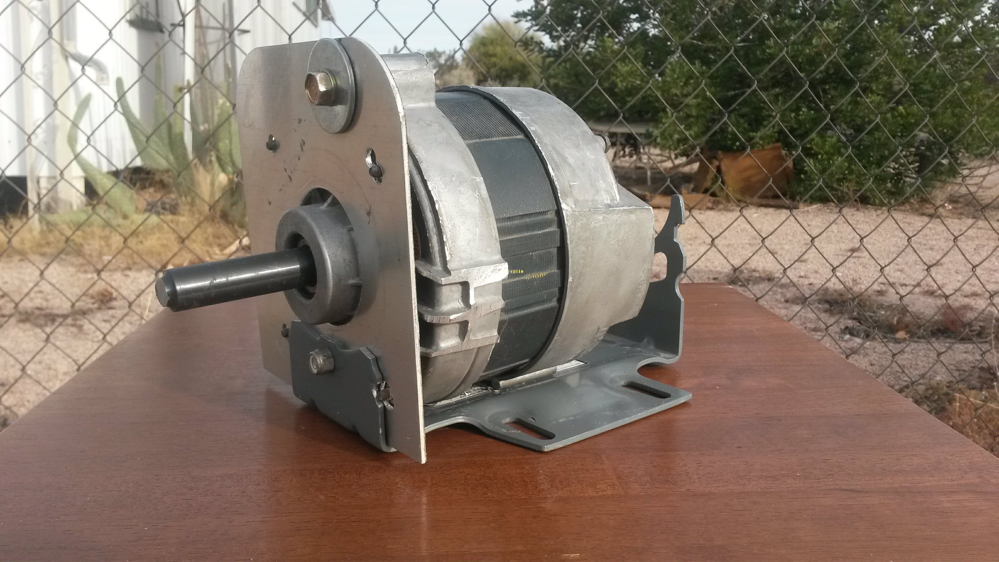
    This motor turned out to be difficult to mount due to the odd shape and lack of mounting holes.  I cut off the grooved pulley from the shaft in order to be able to mount a standard 5/8" V belt pulley but I had to ream out the hole in the pulley to 17mm.  I also cut off the 2 big tabs that stick out on the side to get them out of the way.  I fashioned a motor mount that will give me a flat base to bolt the motor on with by using a swamp cooler motor base from Home Depot that sells for $10.50 and cutting out a flat plate to go over the front of the motor that bolts on with the one mounting bolt.  The 4 bolts in the motor don't appear very strong and were not long enough to mount it with so I just cut out holes to allow them clearance through the plate.  It's not shown in the photo but there is going to also be a U shaped clamp around the back of the motor to hold it securely in place.

View all 3 project logs

  • 1
    Use A Commercial VFD 3 Phase Variable Speed Control

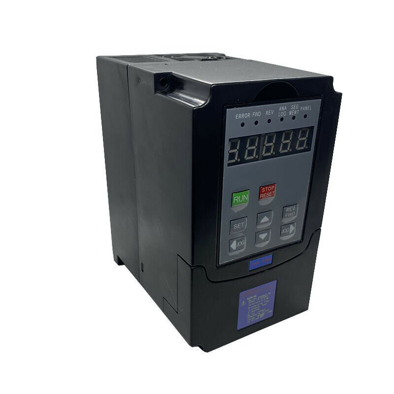
    I've found that the best way to run the Maytag motor is to get a commercial speed control like this one on Ebay for around $60-$70. 

View all instructions

Enjoy this project?

Share

Discussions

paul_aitchison wrote 04/10/2021 at 01:33 point

I have finally completed my Maytag Neptune Switched Reluctance Induction Motor controller with Jerry Trantow's help. I have mounted the motor and controller on my Eastwood "Bead Roller" along with a 100 : 1 worm gear reduction box and the Neptune 14:1 micro belt drive giving a total 1400:1` reduction of the 22,000 Rpm motor to give a useful variable final drive speed of ~ 16 Rpm. The controller uses the Maytag motor controller circuit board and a 10 VDC power supply to drive the programmable XY-PWM-1 Pulse Width controller found on e-bay. I will if I can figure out how to down load a circuit drawing (DWG) and 3 photos of the completed unit sans the safety guarding (yet to be fabricated).

Paul

  Are you sure? yes | no

Barney Wood wrote 04/25/2020 at 19:48 point

What pin are you using as a reference for the PWM signal input to the motor controller board?  The White Line Neutral wire or the +24v  on JP4?

  Are you sure? yes | no

Andrew wrote 05/05/2019 at 19:46 point

Hi, I have all the necessary hardware for the Maytag speed control project you shown, The only difference is that I have an Arduino uno instead and I don’t know where to look for the PWM.h library. Appreciate your help.

  Are you sure? yes | no

Steve wrote 02/03/2018 at 20:13 point

Since the grooved pulley is larger than the shaft and prevents putting on a V belt pulley I sawed it off  with a band saw.  The shaft on the older motor is smaller at the end where the pulley is mounted and really soft steel and is easy to cut.  The shaft on this old model is 17mm in diameter and pretty long so that still leaves a lot to mount a V belt pulley on.  On newer motors with a shorter 2" shaft that is 15mm in diameter I wouldn't cut the shaft since that would only leave 1" sticking out.  In that case I'd either use a puller to remove the pulley or cut a slot into the side of it and break it off. 

  Are you sure? yes | no

Jerry Trantow wrote 01/22/2018 at 17:57 point

Looks good! I am planning to use the original mounting tabs. I will either drill two holes for the tabs or drill through the tabs and insert a bolt through both tabs. This will allow the motor to rotate. I intend to use some big springs to hold it in position. This is similar to how the motor on my table saw is mounted. Uses the weight of the motor (and the spring) to tension the belt. 

What did you use to cut the grooved pulley? I haven't decided if I'm going to keep that piece.

  Are you sure? yes | no

Similar Projects

Does this project spark your interest?

Become a member to follow this project and never miss any updates